relay DODGE RAM SRT-10 2006 Service Repair Manual
[x] Cancel search | Manufacturer: DODGE, Model Year: 2006, Model line: RAM SRT-10, Model: DODGE RAM SRT-10 2006Pages: 5267, PDF Size: 68.7 MB
Page 12 of 5267

P0685-AUTO SHUTDOWN RELAY CONTROL CIRCUIT
For a complete wiring diagramRefer to Section 8W.
Page 13 of 5267
When Monitored:
With ignition on. Battery voltage above 10 volts.
Set Condition:
The actual ASD state is not equal to the desired ASD state. One Trip Fault. Three good trips to turn off the
MIL.
Possible Causes
INTERNAL FUSED B+ CIRCUITS
(K51) ASD RELAY CONTROL CIRCUIT OPEN
(K51) ASD RELAY CONTROL CIRCUIT SHORTED TO GROUND
ASD RELAY
PCM
Always perform the Pre-Diagnostic Troubleshooting procedure before proceeding. (Refer to 9 - ENGINE -
DIAGNOSIS AND TESTING).
Diagnostic Test
1.ASD RELAY OPERATION
Ignition on, engine not running.
With a scan tool, actuate the ASD Relay.
Is the ASD Relay operating?
Ye s>>
Refer to the INTERMITTENT CONDITION Diagnostic Procedure.
Perform the POWERTRAIN VERIFICATION TEST. (Refer to 9 - ENGINE - STANDARD PROCEDURE)
No>>
Go To 2
2.INTERNAL FUSED B+ CIRCUITS
Turn the ignition off.
Remove the ASD Relay from the IPM.
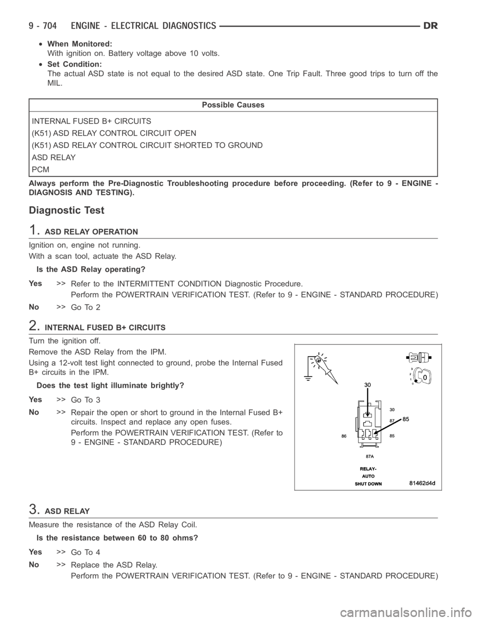
Using a 12-volt test light connected to ground, probe the Internal Fused
B+ circuits in the IPM.
Does the test light illuminate brightly?
Ye s>>
Go To 3
No>>
Repair the open or short to ground in the Internal Fused B+
circuits. Inspect and replace any open fuses.
Perform the POWERTRAIN VERIFICATION TEST. (Refer to
9 - ENGINE - STANDARD PROCEDURE)
3.ASD RELAY
Measure the resistance of the ASD Relay Coil.
Is the resistance between 60 to 80 ohms?
Ye s>>
Go To 4
No>>
Replace the ASD Relay.
Perform the POWERTRAIN VERIFICATION TEST. (Refer to 9 - ENGINE - STANDARD PROCEDURE)
Page 14 of 5267
4.(K51) ASD RELAY CONTROL CIRCUIT OPEN
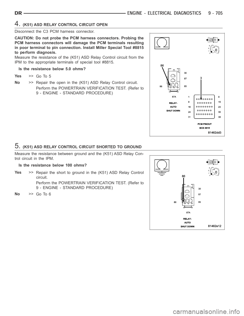
Disconnect the C3 PCM harness connector.
CAUTION: Do not probe the PCM harness connectors. Probing the
PCM harness connectors will damage the PCM terminals resulting
in poor terminal to pin connection. Install Miller Special Tool #8815
to perform diagnosis.
Measure the resistance of the (K51) ASD Relay Control circuit from the
IPM to the appropriate terminals of special tool #8815.
Is the resistance below 5.0 ohms?
Ye s>>
Go To 5
No>>
Repair the open in the (K51) ASD Relay Control circuit.
Perform the POWERTRAIN VERIFICATION TEST. (Refer to
9 - ENGINE - STANDARD PROCEDURE)
5.(K51) ASD RELAY CONTROL CIRCUIT SHORTED TO GROUND
Measure the resistance between ground and the (K51) ASD Relay Con-
trol circuit in the IPM.
Istheresistancebelow100ohms?
Ye s>>
Repair the short to ground in the (K51) ASD Relay Control
circuit.
Perform the POWERTRAIN VERIFICATION TEST. (Refer to
9 - ENGINE - STANDARD PROCEDURE)
No>>
Go To 6
Page 16 of 5267

P0688-AUTO SHUTDOWN RELAY SENSE CIRCUIT LOW
For a complete wiring diagramRefer to Section 8W.
Page 17 of 5267
When Monitored:
With ignition key on. Battery voltage greater than 10 volts.
Set Condition:
No voltage sensed at the PCM when the ASD relay is energized. One Trip Fault.Three good trips to turn off
the MIL.
Possible Causes
INTERNAL FUSED B+ CIRCUITS
(K342) ASD RELAY OUTPUT CIRCUIT OPEN
ASD RELAY
PCM
Always perform the Pre-Diagnostic Troubleshooting procedure before proceeding. (Refer to 9 - ENGINE -
DIAGNOSIS AND TESTING).
Diagnostic Test
1.VERIFY ASD DTC
NOTE: Diagnose P0685 - Auto Shutdown Relay Control Circuit first if it set along with this DTC.
With a scan tool, erase the DTC.
Attempt to start the engine. If the engine will not start, crank the engine for at least 15 seconds. It may be neces-
sary to repeat several times.
Does the DTC reset?
Ye s>>
Go To 2
No>>
Refer to the INTERMITTENT CONDITION Diagnostic Procedure.
Perform the POWERTRAIN VERIFICATION TEST. (Refer to 9 - ENGINE - STANDARD PROCEDURE)
2.ENGINE OPERATION
Attempt to start the engine.
Doestheenginestart?
Ye s>>
Go To 3
No>>
Go To 4
Page 18 of 5267
3.(K342) ASD RELAY OUTPUT CIRCUIT OPEN
Turn the ignition off.
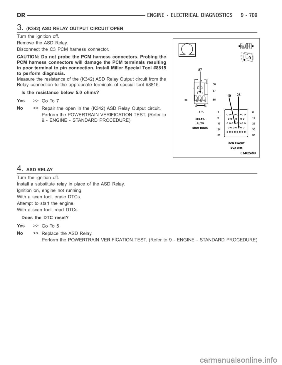
Remove the ASD Relay.
Disconnect the C3 PCM harness connector.
CAUTION: Do not probe the PCM harness connectors. Probing the
PCM harness connectors will damage the PCM terminals resulting
in poor terminal to pin connection. Install Miller Special Tool #8815
to perform diagnosis.
Measure the resistance of the (K342) ASD Relay Output circuit from the
Relay connection to the appropriate terminals of special tool #8815.
Is the resistance below 5.0 ohms?
Ye s>>
Go To 7
No>>
Repair the open in the (K342)ASD Relay Output circuit.
Perform the POWERTRAIN VERIFICATION TEST. (Refer to
9 - ENGINE - STANDARD PROCEDURE)
4.ASD RELAY
Turn the ignition off.
Install a substitute relay in place of the ASD Relay.
Ignition on, engine not running.
With a scan tool, erase DTCs.
Attempt to start the engine.
With a scan tool, read DTCs.
Does the DTC reset?
Ye s>>
Go To 5
No>>
Replace the ASD Relay.
Perform the POWERTRAIN VERIFICATION TEST. (Refer to 9 - ENGINE - STANDARD PROCEDURE)
Page 19 of 5267
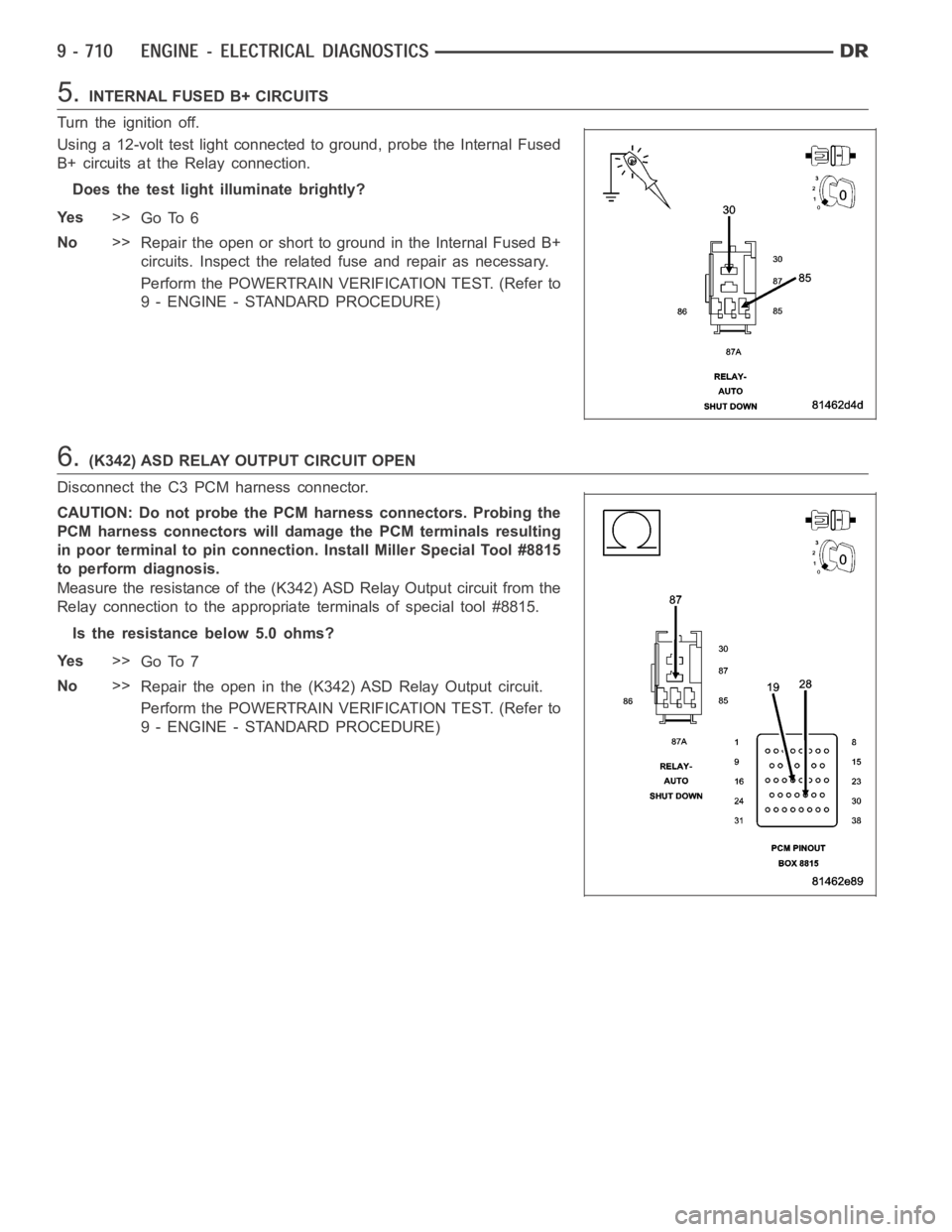
5.INTERNAL FUSED B+ CIRCUITS
Turn the ignition off.
Using a 12-volt test light connected to ground, probe the Internal Fused
B+ circuits at the Relay connection.
Does the test light illuminate brightly?
Ye s>>
Go To 6
No>>
Repair the open or short to ground in the Internal Fused B+
circuits. Inspect the related fuse and repair as necessary.
Perform the POWERTRAIN VERIFICATION TEST. (Refer to
9 - ENGINE - STANDARD PROCEDURE)
6.(K342) ASD RELAY OUTPUT CIRCUIT OPEN
Disconnect the C3 PCM harness connector.
CAUTION: Do not probe the PCM harness connectors. Probing the
PCM harness connectors will damage the PCM terminals resulting
in poor terminal to pin connection. Install Miller Special Tool #8815
to perform diagnosis.
Measure the resistance of the (K342) ASD Relay Output circuit from the
Relay connection to the appropriate terminals of special tool #8815.
Is the resistance below 5.0 ohms?
Ye s>>
Go To 7
No>>
Repair the open in the (K342)ASD Relay Output circuit.
Perform the POWERTRAIN VERIFICATION TEST. (Refer to
9 - ENGINE - STANDARD PROCEDURE)
Page 28 of 5267
Theory of Operation
The Park Neutral switch rationality test is enabled only for vehicles equipped with a 4/5 speed automatic transmis-
sion. This diagnostic checks if the park/neutral switch is incorrectly stuck in the neutral position during driving con-
ditions by comparing Vehicle Speed, Engine Speed, Throttle Position, andPressure Ratio to the fail thresholds and
by looking at the state of the Park/Neutral Switch. The stuck in drive condition is not explicitly checked as the starter
relay does not energize and therefore render the vehicle inoperable.
When Monitored:
Continuously with the transmission in Park, Neutral, or Drive and NOT in Limp-in mode.
Set Condition:
This code will set if the PCM detects an incorrect Park/Neutral switch state for a given mode of vehicle oper-
ation. One trip fault. Three good trips to turn off the MIL.
Possible Causes
TRS (T41) SENSE (P/N SENSE) CIRCUIT OPEN
TRS (T41) SENSE (P/N SENSE) CIRCUIT SHORTED TO GROUND
TRANSMISSION RANGE SENSOR
PCM
Always perform the Pre-Diagnostic Troubleshooting procedure before proceeding. (Refer to 9 - ENGINE -
DIAGNOSIS AND TESTING).
Diagnostic Test
1.P/N AND D/R NOT IN CORRECT POSITION
NOTE: Check the TCM for DTCs, if P0706 is set in the TCM diagnose the TCM code before continuing.
Ignition on, engine not running.
With the scan tool, read the Park/Neutral Position Switch input state.
While moving the gear selector through all gear positions (Park to 1 and back to Park), monitor the scan tool dis-
play.
Did the scan tool display show P/N and D/R in the correct gear positions?
Ye s>>
Refer to the INTERMITTENT CONDITION Diagnostic Procedure.
Perform the POWERTRAIN VERIFICATION TEST. (Refer to 9 - ENGINE - STANDARD PROCEDURE)
No>>
Go To 2
Page 54 of 5267
When Monitored:
With the ignition on. Battery voltage greater than 10 volts. A/C Switch on.
Set Condition:
A shorted condition is detected in the A/C clutch relay control circuit. One Trip Fault. Three good trips to turn
off the MIL.
Possible Causes
(C3) A/C COMPRESSOR CLUTCH CONTROL CIRCUIT SHORTED TO GROUND
A/C COMPRESSOR CLUTCH
TIPM
Always perform the Pre-Diagnostic Troubleshooting procedure before proceeding. (Refer to 9 - ENGINE -
DIAGNOSIS AND TESTING).
Diagnostic Test
1.A/C COMPRESSOR CLUTCH OPERATION
Ignition on, engine not running.
With a scan tool under the PCM Actuators, actuate the A/C Clutch.
Is the A/C Clutch actuating?
Ye s>>
Refer to the INTERMITTENT CONDITION Diagnostic Procedure.
Perform the POWERTRAIN VERIFICATION TEST. (Refer to 9 - ENGINE - STANDARD PROCEDURE)
No>>
Go To 2
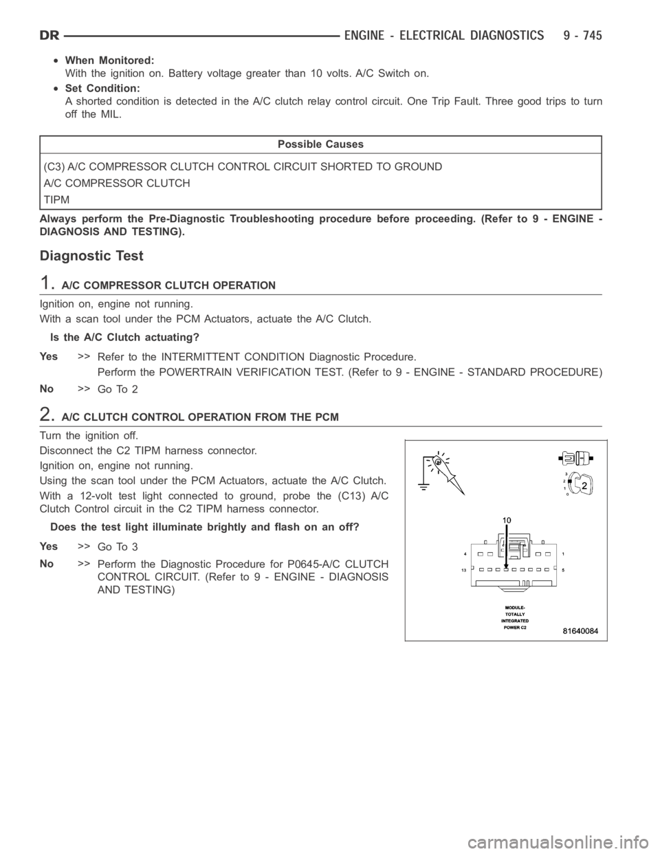
2.A/C CLUTCH CONTROL OPERATION FROM THE PCM
Turn the ignition off.
Disconnect the C2 TIPM harness connector.
Ignition on, engine not running.
Using the scan tool under the PCM Actuators, actuate the A/C Clutch.
With a 12-volt test light connected to ground, probe the (C13) A/C
Clutch Control circuit in the C2 TIPM harness connector.
Does the test light illuminate brightly and flash on an off?
Ye s>>
Go To 3
No>>
Perform the Diagnostic Procedure for P0645-A/C CLUTCH
CONTROL CIRCUIT. (Refer to 9 - ENGINE - DIAGNOSIS
AND TESTING)
Page 68 of 5267
When Monitored:
With the ignition on. Battery voltage greater than 10.4 volts and the ASD sense switch is on.
Set Condition:
Actual Starter state is not equal to desired state. One Trip Fault. Three goodtripstoturnofftheMIL.
Possible Causes
(T40) STARTER RELAY OUTPUT CIRCUIT SHORTED TO GROUND
(T750) STARTER RELAY OUTPUT CIRCUIT SHORTED TO GROUND
STARTER RELAY
STARTER
TIPM
Always perform the Pre-Diagnostic Troubleshooting procedure before proceeding. (Refer to 9 - ENGINE -
DIAGNOSIS AND TESTING).
Diagnostic Test
1.ACTIVE DTC
Ignition on, engine not running.
With a scan tool, read DTCs.
Is the DTC active at this time?
Ye s>>
Go To 2
No>>
Refer to the INTERMITTENT CONDITION Diagnostic Procedure.
Perform the POWERTRAIN VERIFICATION TEST. (Refer to 9 - ENGINE - STANDARD PROCEDURE)
2.(T40) STARTER FEED CIRCUIT SHORTED TO GROUND
Turn the ignition.
Disconnect the Starter Relay.
Disconnect the C9 TIPM harness connector.
Measure the resistance between ground and the (T40) Starter Relay Output circuit in the C9 TIPM harness con-
nector.
Istheresistancebelow100ohms?
Ye s>>
Repair the short to ground in the (T40) Starter Relay Output circuit.
Perform the POWERTRAIN VERIFICATION TEST. (Refer to 9 - ENGINE - STANDARD PROCEDURE)
No>>
Go To 3
3.(T750) STARTER RELAY OUTPUT CIRCUIT SHORTED TO GROUND
Disconnect the Starter Solenoid connector.
Measure the resistance between ground and the (T750) Starter Relay Outputcircuit in the Starter Relay harness
connector.
Istheresistancebelow100ohms?
Ye s>>
Repair the short to ground in the (T750) Starter Relay Output circuit.
Perform the POWERTRAIN VERIFICATION TEST. (Refer to 9 - ENGINE - STANDARD PROCEDURE)
No>>
Go To 4