tow DODGE RAM SRT-10 2006 Service Repair Manual
[x] Cancel search | Manufacturer: DODGE, Model Year: 2006, Model line: RAM SRT-10, Model: DODGE RAM SRT-10 2006Pages: 5267, PDF Size: 68.7 MB
Page 4609 of 5267
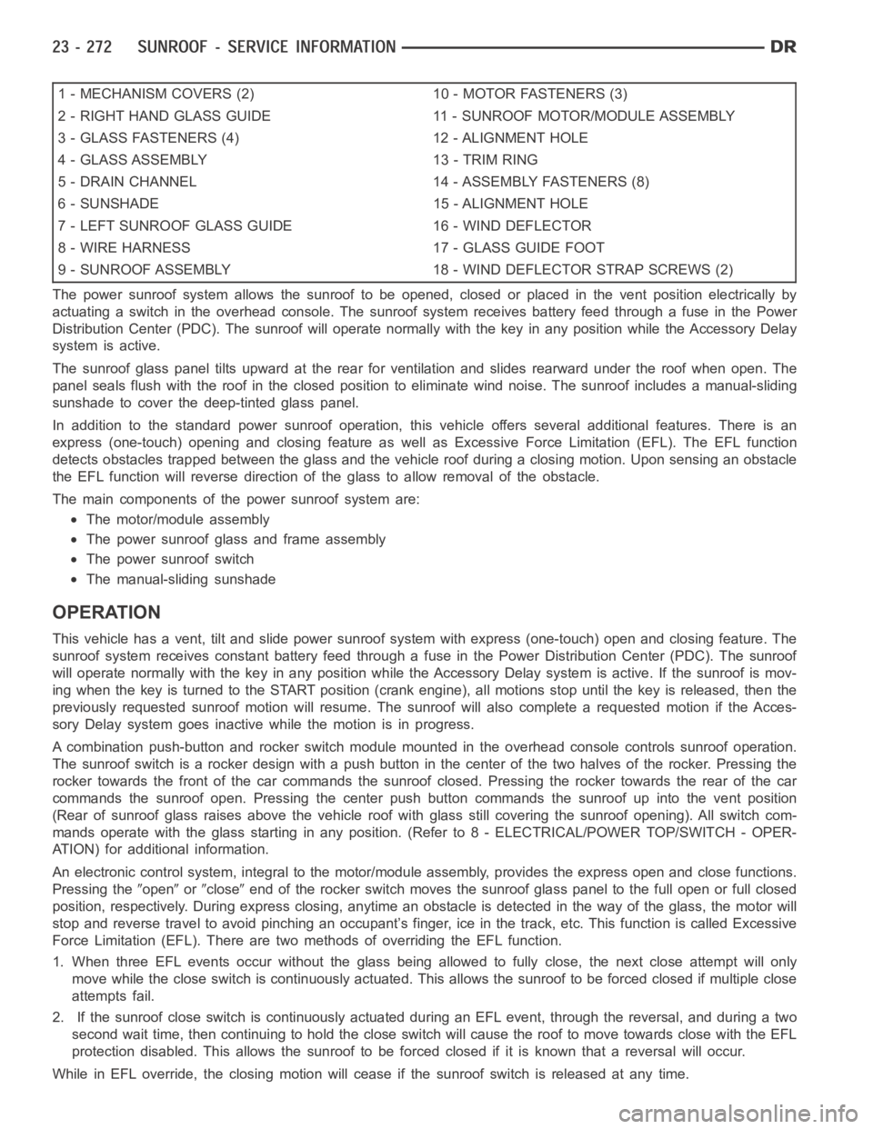
1 - MECHANISM COVERS (2) 10 - MOTOR FASTENERS (3)
2 - RIGHT HAND GLASS GUIDE 11 - SUNROOF MOTOR/MODULE ASSEMBLY
3 - GLASS FASTENERS (4) 12 - ALIGNMENT HOLE
4 - GLASS ASSEMBLY 13 - TRIM RING
5 - DRAIN CHANNEL 14 - ASSEMBLY FASTENERS (8)
6 - SUNSHADE 15 - ALIGNMENT HOLE
7 - LEFT SUNROOF GLASS GUIDE 16 - WIND DEFLECTOR
8 - WIRE HARNESS 17 - GLASS GUIDE FOOT
9 - SUNROOF ASSEMBLY 18 - WIND DEFLECTOR STRAP SCREWS (2)
The power sunroof system allows the sunroof to be opened, closed or placed in the vent position electrically by
actuating a switch in the overhead console. The sunroof system receives battery feed through a fuse in the Power
Distribution Center (PDC). The sunroof will operate normally with the keyin any position while the Accessory Delay
system is active.
The sunroof glass panel tilts upward at the rear for ventilation and slidesrearward under the roof when open. The
panel seals flush with the roof in the closed position to eliminate wind noise. The sunroof includes a manual-sliding
sunshade to cover the deep-tinted glass panel.
In addition to the standard power sunroof operation, this vehicle offers several additional features. There is an
express (one-touch) opening and closing feature as well as Excessive Force Limitation (EFL). The EFL function
detects obstacles trapped between the glass and the vehicle roof during a closing motion. Upon sensing an obstacle
the EFL function will reverse direction of the glass to allow removal of theobstacle.
The main components of thepower sunroof system are:
The motor/module assembly
The power sunroof glass and frame assembly
The power sunroof switch
The manual-sliding sunshade
OPERATION
This vehicle has a vent, tilt and slide power sunroof system with express (one-touch) open and closing feature. The
sunroof system receives constant battery feed through a fuse in the Power Distribution Center (PDC). The sunroof
will operate normally with the key in any position while the Accessory Delay system is active. If the sunroof is mov-
ing when the key is turned to the START position (crank engine), all motionsstop until the key is released, then the
previously requested sunroof motion will resume. The sunroof will also complete a requested motion if the Acces-
sory Delay system goes inactivewhile the motion is in progress.
A combination push-button and rocker switch module mounted in the overhead console controls sunroof operation.
The sunroof switch is a rocker design with a push button in the center of the two halves of the rocker. Pressing the
rocker towards the front of the car commands the sunroof closed. Pressing the rocker towards the rear of the car
commands the sunroof open. Pressing the center push button commands the sunroof up into the vent position
(Rear of sunroof glass raises above the vehicle roof with glass still covering the sunroof opening). All switch com-
mands operate with the glass startingin any position. (Refer to 8 - ELECTRICAL/POWER TOP/SWITCH - OPER-
ATION) for additional information.
An electronic control system, integralto the motor/module assembly, provides the express open and close functions.
Pressing the
openorcloseend of the rocker switch moves the sunroof glass panel to the full open or fullclosed
position, respectively. During express closing, anytime an obstacle is detected in the way of the glass, the motor will
stop and reverse travel to avoid pinching an occupant’s finger, ice in the track, etc. This function is called Excessive
Force Limitation (EFL). There are two methods of overriding the EFL function.
1. When three EFL events occur without the glass being allowed to fully close, the next close attempt will only
move while the close switch is continuously actuated. This allows the sunrooftobeforcedclosedifmultipleclose
attempts fail.
2. If the sunroof close switch is continuously actuated during an EFL event, through the reversal, and during a two
second wait time, then continuing to hold the close switch will cause the roof to move towards close with the EFL
protection disabled. This allows the sunroof to be forced closed if it is known that a reversal will occur.
While in EFL override, the closing motion will cease if the sunroof switch is released at any time.
Page 4610 of 5267
The motor/module is programmed to learn the speed required to drive the panel based on position and recalibrates
itself as needed. If the sunroof becomes uncalibrated, it will only respond to the vent switch. If the vent switch is
pressed, the glass will move toward vent; if the switch is released, all motion stops. In the event that the sunroof
system becomes uncalibrated performthe sunroof position calibration procedure, (Refer to 8 - ELECTRICAL/
POWER TOP/MOTOR - STANDARD PROCEDURE -SUNROOF POSITION CALIBRATION).
DIAGNOSIS AND TESTING
POWER TOP - SUNROOF
Any diagnosis of the power sunroof system should begin with the use of a scantool and the proper Diagnostic
Procedures Information. The scan tool can provide confirmation that the Controller Area Network (CAN) Data Bus is
functional, that all of the electronic modules are sending and receiving the proper messages on the CAN Data Bus,
and that the power sunroof motor is being sent the proper hard wired output by the sunroof switch.
For complete circuit diagrams, refer to the appropriate wiring information. The wiring information includes wiring dia-
grams, proper wire and connector repair procedures, details of wire harness routing and retention, connector pin-out
information and location views for the various wire harness connectors, splices and grounds.
Refer to the appropriate diagnostic information.
SUNROOF
Refer to SUNROOF DIAGNOSIS CHART for possible causes. Before beginning sunroof diagnostics verify that all
other power accessories are in proper operating condition. If not, a common electrical problem may exist. Refer to
Wiring Diagrams, in this publication for circuit, splice and component descriptions. Check the condition of the circuit
protection (20 amp circuit breaker in the Junction Block). Inspect all wiring connector pins for proper engagement
and continuity. Check for battery voltage at the power sunroof controller, refer to Wiring Diagrams, for circuit infor-
mation. If battery voltage of more than 10 volts is detected at the controller, proceed with the following tests (the
controller will not operate at less than 10 volts).
Before beginning diagnosis for wind noise or water leaks, verify that the problem was not caused by releasing the
control switch before the sunroof was fully closed. The sunroof module hasa water-management system. If how-
ever, the sunroof glass is in a partial closed position, high pressure water may be forced beyond the water man-
agement system boundariesand onto the headlining.
Every time the sunroof module loses power it must be initialized. This is done by connecting power to the sunroof
and moving the sunroof toward the closed position. When initialization occurs a slight “kick” in the sunroof module
will be seen and heard. This is the indication that the sunroof module is initialized
SUNROOF DIAGNOSIS CHART
SYMPTOM POSSIBLE CAUSE
Sunroof motor inoperative. Faulty control switch.
Faulty circuit ground between sunroof module, control switch,
and body harness.
Faulty power circuit between sunroof module, control switch,
and body harness.
Faulty sunroof drive motor.
Faulty sunroof module.
Audible whine when switch is depressed,
sunroof does not operate.Faulty sunroof drive motor.
Binding cable.
Audible clicking or ratcheting when switch is
pressed, sunroof does not operate.Broken or worn drive cable.
Worn drive motor gear.
Mechanisms not synchronized.
Page 4693 of 5267
INSTALLATION
WARNING: Always keep hands and clothing clear
of the wire rope, hook and fairlead opening during
operation and when spooling. Failure to follow
these instructions may result in personal injury or
death.
CAUTION: Wire rope must spool on the winch
drum in the direction indicated.
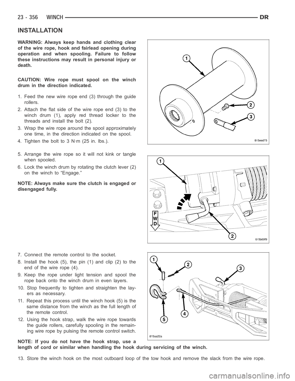
1. Feed the new wire rope end (3) through the guide
rollers.
2. Attach the flat side of the wire rope end (3) to the
winch drum (1), apply red thread locker to the
threads and install the bolt (2).
3. Wrap the wire rope around the spool approximately
one time, in the direction indicated on the spool.
4. Tighten the bolt to 3 Nꞏm (25 in. lbs.).
5. Arrange the wire rope so it will not kink or tangle
when spooled.
6. Lock the winch drum by rotating the clutch lever (2)
on the winch to “Engage.”
NOTE: Always make sure the clutch is engaged or
disengaged fully.
7. Connect the remote control to the socket.
8. Install the hook (5), the pin (1) and clip (2) to the
end of the wire rope (4).
9. Keep the rope under light tension and spool the
rope back onto the winch drum in even layers.
10. Stop frequently to tighten and straighten the lay-
ers as necessary.
11. Repeat this process until the winch hook (5) is the
same distance from the winch as the full length of
theremotecontrol.
12. Using the hook strap, walk the wire rope towards
the guide rollers, carefully spooling in the remain-
ing wire rope by pulsing the remote control switch.
NOTE: If you do not have the hook strap, use a
length of cord or similar when handling the hook during servicing of the winch.
13. Store the winch hook on the most outboard loop of the tow hook and remove the slack from the wire rope.
Page 4697 of 5267
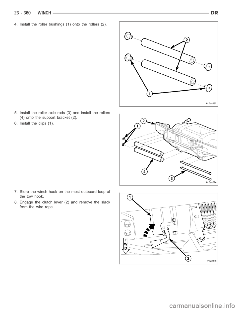
4. Install the roller bushings (1) onto the rollers (2).
5. Install the roller axle rods (3) and install the rollers
(4) onto the support bracket (2).
6. Install the clips (1).
7. Store the winch hook on the most outboard loop of
the tow hook.
8. Engage the clutch lever (2) and remove the slack
fromthewirerope.
Page 4949 of 5267
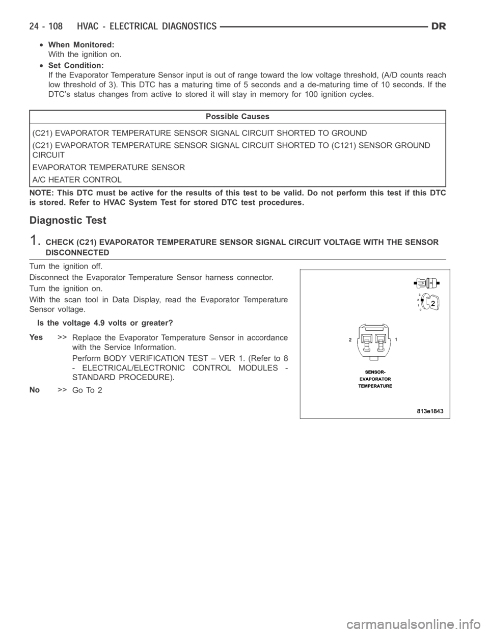
When Monitored:
With the ignition on.
Set Condition:
If the Evaporator Temperature Sensor input is out of range toward the low voltage threshold, (A/D counts reach
low threshold of 3). This DTC has a maturing time of 5 seconds and a de-maturing time of 10 seconds. If the
DTC’s status changes from active to stored it will stay in memory for 100 ignition cycles.
Possible Causes
(C21) EVAPORATOR TEMPERATURE SENSOR SIGNAL CIRCUIT SHORTED TO GROUND
(C21) EVAPORATOR TEMPERATURE SENSOR SIGNAL CIRCUIT SHORTED TO (C121) SENSOR GROUND
CIRCUIT
EVAPORATOR TEMPERATURE SENSOR
A/C HEATER CONTROL
NOTE: This DTC must be active for the results of this test to be valid. Do not perform this test if this DTC
is stored. Refer to HVAC System Test for stored DTC test procedures.
Diagnostic Test
1.CHECK (C21) EVAPORATOR TEMPERATURE SENSOR SIGNAL CIRCUIT VOLTAGE WITH THE SENSOR
DISCONNECTED
Turn the ignition off.
Disconnect the Evaporator Temperature Sensor harness connector.
Turn the ignition on.
With the scan tool in Data Display, read the Evaporator Temperature
Sensor voltage.
Is the voltage 4.9 volts or greater?
Ye s>>
Replace the Evaporator Temperature Sensor in accordance
with the Service Information.
Perform BODY VERIFICATION TEST – VER 1. (Refer to 8
- ELECTRICAL/ELECTRONIC CONTROL MODULES -
STANDARD PROCEDURE).
No>>
Go To 2
Page 4952 of 5267
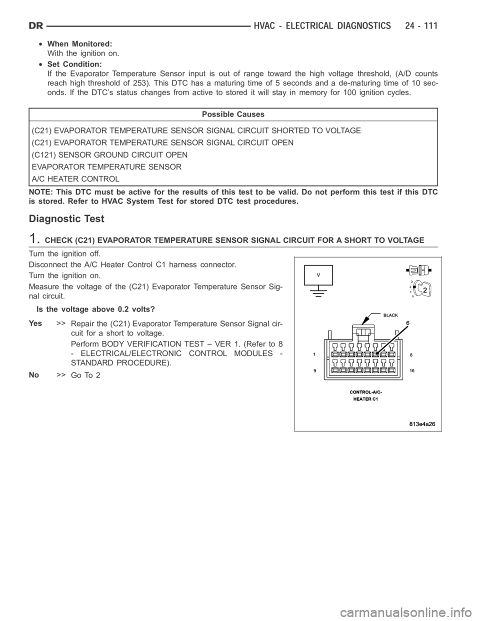
When Monitored:
With the ignition on.
Set Condition:
If the Evaporator Temperature Sensor input is out of range toward the high voltage threshold, (A/D counts
reach high threshold of 253). This DTC has a maturing time of 5 seconds and a de-maturing time of 10 sec-
onds. If the DTC’s status changes from active to stored it will stay in memory for 100 ignition cycles.
Possible Causes
(C21) EVAPORATOR TEMPERATURE SENSOR SIGNAL CIRCUIT SHORTED TO VOLTAGE
(C21) EVAPORATOR TEMPERATURE SENSOR SIGNAL CIRCUIT OPEN
(C121) SENSOR GROUND CIRCUIT OPEN
EVAPORATOR TEMPERATURE SENSOR
A/C HEATER CONTROL
NOTE: This DTC must be active for the results of this test to be valid. Do not perform this test if this DTC
is stored. Refer to HVAC System Test for stored DTC test procedures.
Diagnostic Test
1.CHECK (C21) EVAPORATOR TEMPERATURE SENSOR SIGNAL CIRCUIT FOR A SHORT TO VOLTA G E
Turn the ignition off.
Disconnect the A/C Heater Control C1 harness connector.
Turn the ignition on.
Measure the voltage of the (C21) Evaporator Temperature Sensor Sig-
nal circuit.
Is the voltage above 0.2 volts?
Ye s>>
Repair the (C21) Evaporator Temperature Sensor Signal cir-
cuit for a short to voltage.
Perform BODY VERIFICATION TEST – VER 1. (Refer to 8
- ELECTRICAL/ELECTRONIC CONTROL MODULES -
STANDARD PROCEDURE).
No>>
Go To 2
Page 5224 of 5267
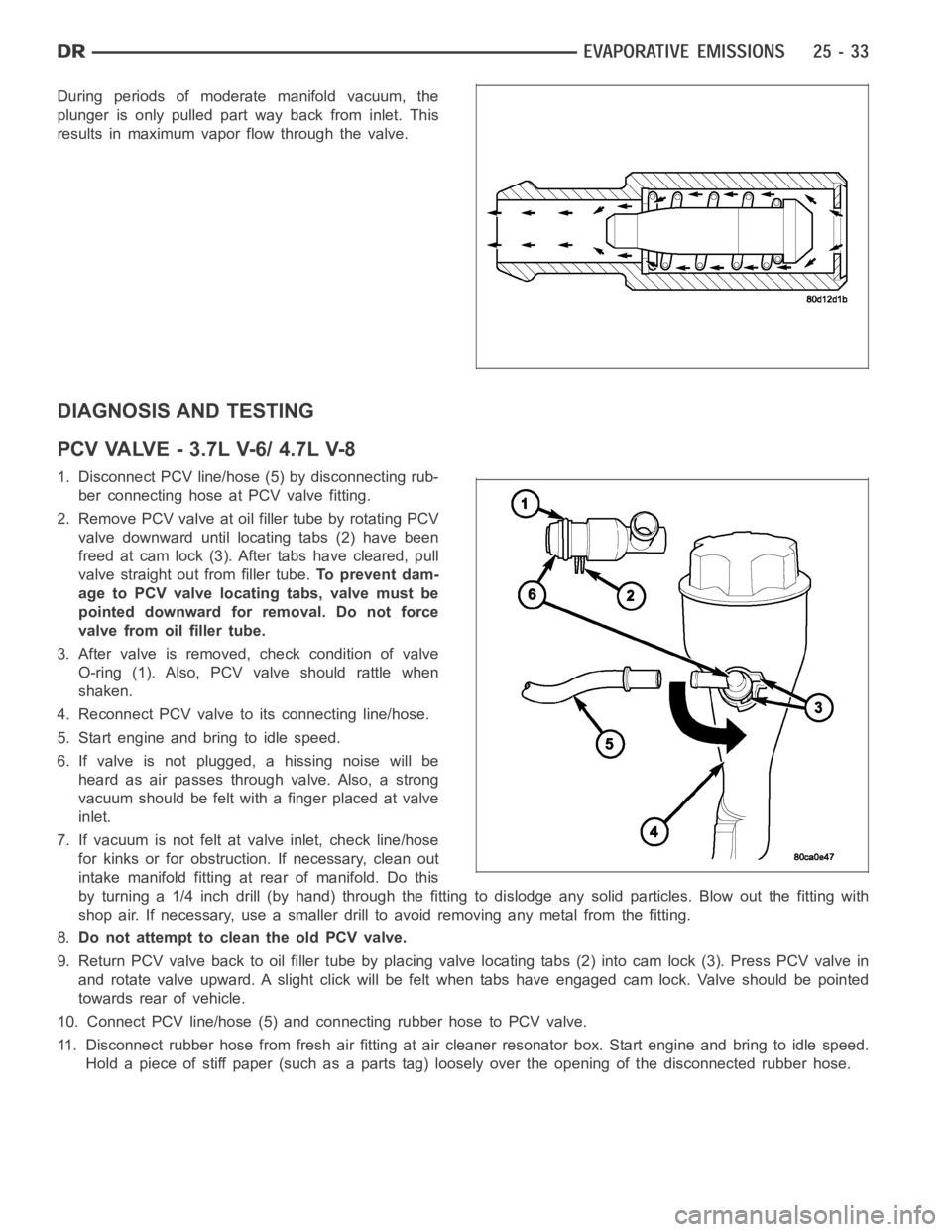
During periods of moderate manifold vacuum, the
plunger is only pulled part way back from inlet. This
results in maximum vapor flow through the valve.
DIAGNOSIS AND TESTING
PCVVALVE-3.7LV-6/4.7LV-8
1. Disconnect PCV line/hose (5) by disconnecting rub-
ber connecting hose at PCV valve fitting.
2. Remove PCV valve at oil filler tube by rotating PCV
valve downward until locating tabs (2) have been
freed at cam lock (3). After tabs have cleared, pull
valve straight out from filler tube.To prevent dam-
age to PCV valve locating tabs, valve must be
pointed downward for removal. Do not force
valve from oil filler tube.
3. After valve is removed, check condition of valve
O-ring (1). Also, PCV valve should rattle when
shaken.
4. Reconnect PCV valve to its connecting line/hose.
5. Start engine and bring to idle speed.
6. If valve is not plugged, a hissing noise will be
heard as air passes through valve. Also, a strong
vacuum should be felt with a finger placed at valve
inlet.
7. If vacuum is not felt at valve inlet, check line/hose
for kinks or for obstruction. If necessary, clean out
intake manifold fitting at rear of manifold. Do this
byturninga1/4inchdrill(byhand)throughthefittingtodislodgeanysolid particles. Blow out the fitting with
shop air. If necessary, use a smaller drill to avoid removing any metal fromthe fitting.
8.Do not attempt to clean the old PCV valve.
9. Return PCV valve back to oil filler tube by placing valve locating tabs (2) into cam lock (3). Press PCV valve in
and rotate valve upward. A slight click will be felt when tabs have engaged cam lock. Valve should be pointed
towards rear of vehicle.
10. Connect PCV line/hose (5) and connecting rubber hose to PCV valve.
11. Disconnect rubber hose from fresh air fitting at air cleaner resonatorbox. Start engine and bring to idle speed.
Hold a piece of stiff paper (such as a parts tag) loosely over the opening of the disconnected rubber hose.
Page 5227 of 5267
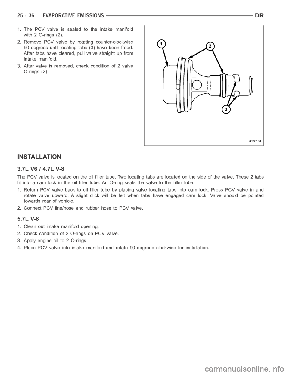
1. The PCV valve is sealed to the intake manifold
with 2 O-rings (2).
2. Remove PCV valve by rotating counter-clockwise
90 degrees until locating tabs (3) have been freed.
After tabs have cleared, pull valve straight up from
intake manifold.
3. After valve is removed, check condition of 2 valve
O-rings (2).
INSTALLATION
3.7L V6 / 4.7L V-8
The PCV valve is located on the oil filler tube. Two locating tabs are locatedonthesideofthevalve.These2tabs
fit into a cam lock in the oil filler tube.An O-ring seals the valve to the filler tube.
1. Return PCV valve back to oil filler tube by placing valve locating tabs into cam lock. Press PCV valve in and
rotate valve upward. A slight click will be felt when tabs have engaged cam lock. Valve should be pointed
towards rear of vehicle.
2. Connect PCV line/hose and rubber hose to PCV valve.
5.7L V-8
1. Clean out intake manifold opening.
2. Check condition of 2 O-rings on PCV valve.
3. Apply engine oil to 2 O-rings.
4. Place PCV valve into intake manifold and rotate 90 degrees clockwise forinstallation.