CD changer DODGE RAM SRT-10 2006 Service Repair Manual
[x] Cancel search | Manufacturer: DODGE, Model Year: 2006, Model line: RAM SRT-10, Model: DODGE RAM SRT-10 2006Pages: 5267, PDF Size: 68.7 MB
Page 2169 of 5267

CHARGE AIR COOLER AND PLUMBING
DESCRIPTION
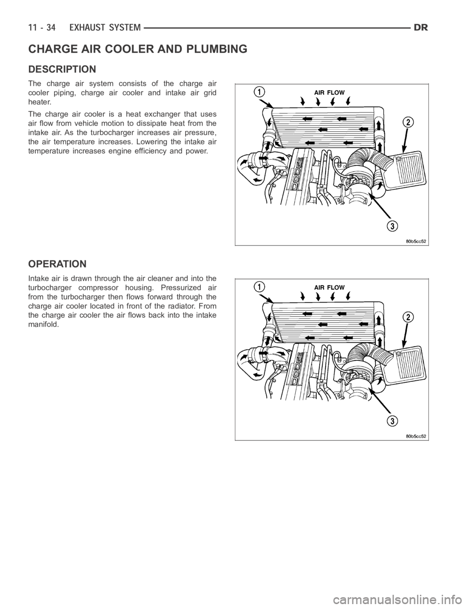
The charge air system consists of the charge air
cooler piping, charge air cooler and intake air grid
heater.
The charge air cooler is a heat exchanger that uses
air flow from vehicle motion to dissipate heat from the
intake air. As the turbocharger increases air pressure,
the air temperature increases. Lowering the intake air
temperature increases engine efficiency and power.
OPERATION
Intake air is drawn through the air cleaner and into the
turbocharger compressor housing. Pressurized air
from the turbocharger then flows forward through the
charge air cooler located in front of the radiator. From
the charge air cooler the air flows back into the intake
manifold.
Page 3000 of 5267

SPECIFICATIONS
42RLE AUTOMATIC TRANSMISSION
GENERAL SPECIFICATIONS
Transmission TypeFour-Speed Automatic, Electronically Controlled, Fully
Adaptive, Electronically Modulated Torque Converter
Lubrication Method Pump (internal - external gear-type)
Cooling Method Water Heat Exchanger and/or Air-to-Oil Heat Exchanger
GEAR RATIOS
1st Gear 2.84:1
2nd Gear 1.57:1
3rd Gear (Direct) 1.00:1
4th Gear (Overdrive) 0.69:1
Reverse Gear 2.21:1
BEARING PRELOAD (Drag Torque)
Description Metric Standard
Output Shaft 0.22-0.903 Nꞏm 1-8 in. lbs.
CLUTCH PACK
Description Metric Standard
Low/Reverse Clutch (Select
Reaction Plate)0.84-1.60 mm 0.033-0.063 in.
Two/Four Clutch (No Select) 0.76-2.64 mm 0.030-0.104 in.
Reverse Clutch (Select Snap Ring) 0.89-1.37 mm 0.035-0.054 in.
Overdrive Clutch (No Select) 1.07-3.25 mm 0.042-0.128 in.
Underdrive Clutch (Select Reaction
Plate)0.94-1.50 mm 0.037-0.059 in.
INPUT SHAFT
Description Metric Standard
End Play 0.127-0.635 mm 0.005-0.025 in.
OIL PUMP CLEARANCES
DESCRIPTION METRIC STANDARD
Outer Gear-to-Crescent 0.060-0.298 mm 0.0023-0.0117 in.
Inner Gear-to-Crescent 0.093-0.385 mm 0.0036-0.0151 in.
Outer Gear-to-Pocket 0.089-0.202 mm 0.0035-0.0079 in.
Outer Gear Side Clearance 0.020-0.046 mm 0.0008-0.0018 in.
Inner Gear Side Clearance 0.020-0.046 mm 0.0008-0.0018 in.
Page 5146 of 5267

CONDENSER-A/C
DESCRIPTION
The A/C condenser is located in the front of the engine compartment behind the grille. The A/C condenser is a heat
exchanger that allows the high-pressure refrigerant gas being dischargedbytheA/Ccompressortogiveupitsheat
to the air passing over the condenser fins, which causes the refrigerant tocool and change to a liquid state.
OPERATION
When air passes through the fins of the A/C condenser, the high-pressure refrigerant gas within the A/C condenser
gives up its heat. The refrigerant then condenses as it leaves the A/C condenser and becomes a high-pressure
liquid. The volume of air flowing over the condenser fins is critical to theproper cooling performance of the A/C
system. Therefore, it is important that there are no objects placed in front of the radiator grille openings at the front
of the vehicle or foreign material on the condenser fins that might obstruct proper air flow. Also, any factory-installed
air seals or shrouds must be properly reinstalled following radiator or A/C condenser service.
The A/C condenser cannot be repaired and, if faulty or damaged, it must be replaced.
REMOVAL
3.7L/4.7L/5.7L ENGINES
WARNING: Refer to the applicable warnings and cautions for this system before performing the following
operation (Refer to 24 - HEATING & AIR CONDITIONING/PLUMBING - WARNINGS) and (Refer to 24 - HEAT-
ING & AIR CONDITIONING/PLUMBING - CAUTIONS). Failure to follow the warnings and cautions could result
in possible personal injury or death.
1. Recover the refrigerant from the refrigerant system
(Refer to 24 - HEATING & AIR CONDITIONING/
PLUMBING - STANDARD PROCEDURE -
REFRIGERANT SYSTEM RECOVERY).
2. Disconnect and isolate the negative battery cable.
3. Disconnect the A/C discharge line and the A/C liq-
uidlinefromtheA/Ccondenser(Referto24-
HEATING & AIR CONDITIONING/PLUMBING/
LINE-A/C DISCHARGE - REMOVAL) and (Refer to
24 - HEATING & AIR CONDITIONING/PLUMBING/
LINE-A/C LIQUID - REMOVAL).
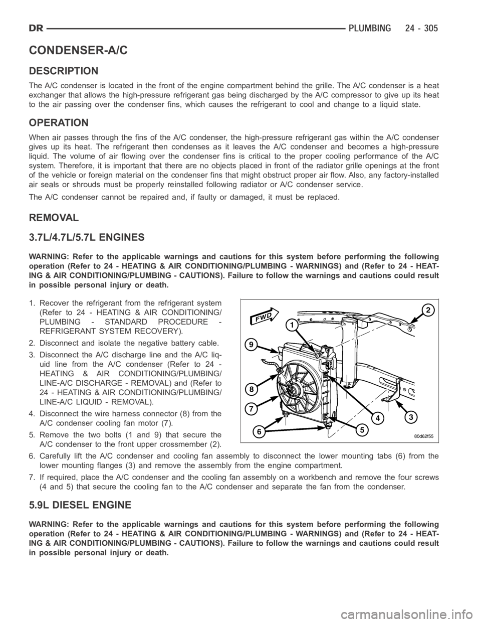
4. Disconnect the wire harness connector (8) from the
A/C condenser cooling fan motor (7).
5. Remove the two bolts (1 and 9) that secure the
A/C condenser to the front upper crossmember (2).
6. Carefully lift the A/C condenser and cooling fan assembly to disconnectthe lower mounting tabs (6) from the
lower mounting flanges (3) and remove the assembly from the engine compartment.
7. If required, place the A/C condenser and the cooling fan assembly on a workbench and remove the four screws
(4 and 5) that secure the cooling fan to the A/C condenser and separate the fan from the condenser.
5.9L DIESEL ENGINE
WARNING: Refer to the applicable warnings and cautions for this system before performing the following
operation (Refer to 24 - HEATING & AIR CONDITIONING/PLUMBING - WARNINGS) and (Refer to 24 - HEAT-
ING & AIR CONDITIONING/PLUMBING - CAUTIONS). Failure to follow the warnings and cautions could result
in possible personal injury or death.
Page 5151 of 5267

CORE-HEATER
DESCRIPTION
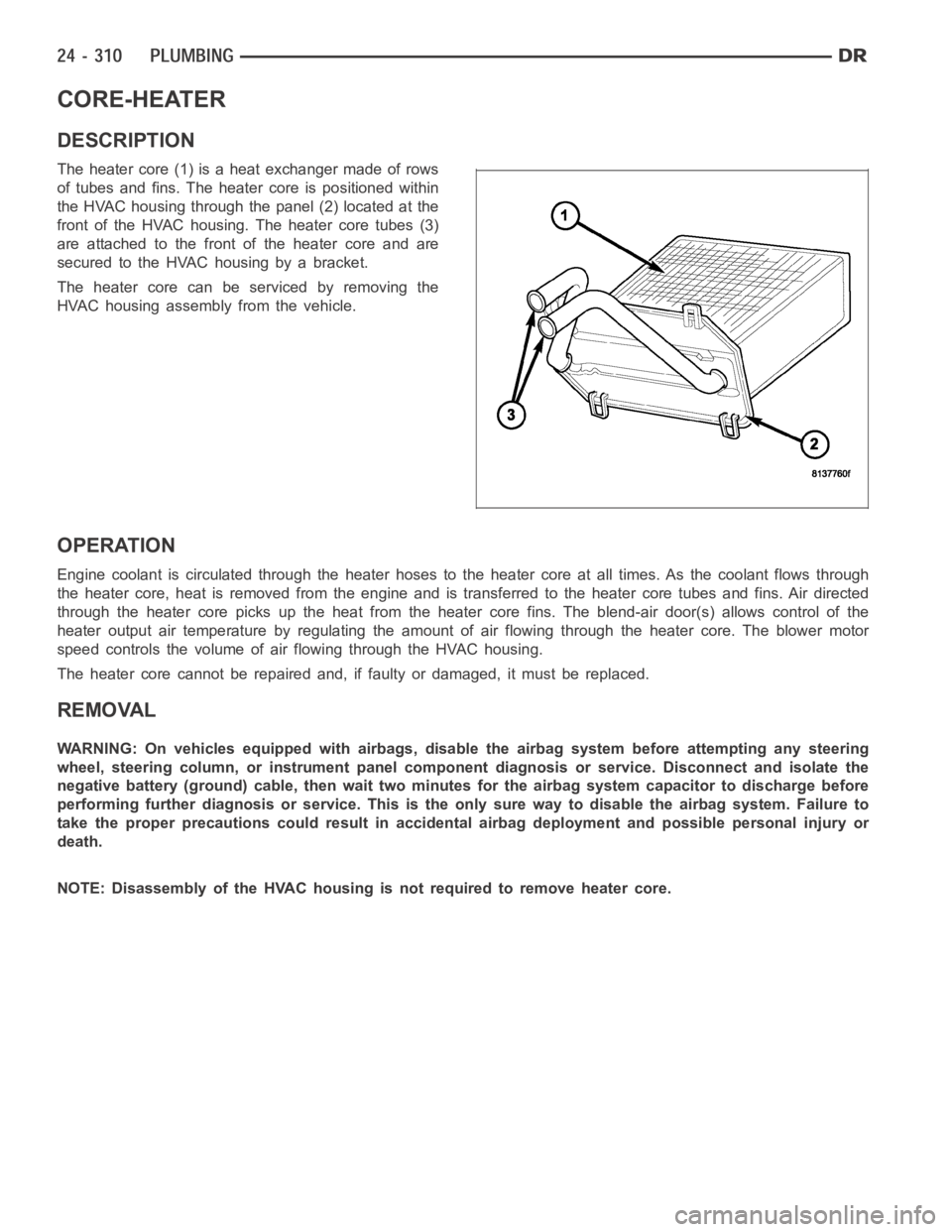
The heater core (1) is a heat exchanger made of rows
of tubes and fins. The heater core is positioned within
the HVAC housing through the panel (2) located at the
front of the HVAC housing. The heater core tubes (3)
are attached to the front of the heater core and are
secured to the HVAC housing by a bracket.
The heater core can be serviced by removing the
HVAC housing assembly from the vehicle.
OPERATION
Engine coolant is circulated through the heater hoses to the heater core atall times. As the coolant flows through
the heater core, heat is removed from the engine and is transferred to the heater core tubes and fins. Air directed
through the heater core picks up the heat from the heater core fins. The blend-air door(s) allows control of the
heater output air temperature by regulating the amount of air flowing through the heater core. The blower motor
speed controls the volume of air flowing through the HVAC housing.
The heater core cannot be repaired and, if faulty or damaged, it must be replaced.
REMOVAL
WARNING: On vehicles equipped with airbags, disable the airbag system before attempting any steering
wheel, steering column, or instrument panel component diagnosis or service. Disconnect and isolate the
negative battery (ground) cable, then wait two minutes for the airbag system capacitor to discharge before
performing further diagnosis or service. This is the only sure way to disable the airbag system. Failure to
take the proper precautions could result in accidental airbag deploymentand possible personal injury or
death.
NOTE: Disassembly of the HVAC housing is not required to remove heater core.