DODGE RAM SRT-10 2006 Service Repair Manual
RAM SRT-10 2006
DODGE
DODGE
https://www.carmanualsonline.info/img/12/56917/w960_56917-0.png
DODGE RAM SRT-10 2006 Service Repair Manual
Trending: wheel, seat memory, battery, oil level, traction control, ad blue, fuel type
Page 2271 of 5267
TA N K - F U E L
DESCRIPTION
The fuel tank is constructed of a plastic material. Its main functions are for fuel storage and for placement of the fuel
pump module, and (if equipped) certain ORVR components.
OPERATION
All models pass a full 360 degree rollover test without fuel leakage. To accomplish this, fuel and vapor flow controls
are required for all fuel tank connections.
Two check (control) valves are mounted into the top of the fuel tank. Refer to Fuel Tank Check Valve for additional
information.
An evaporation control system is connected to the fuel tank to reduce emissions of fuel vapors into the atmosphere.
When fuel evaporates from the fuel tank, vapors pass through vent hoses or tubes to a charcoal canister where
they are temporarily held. When the engine is running, the vapors are drawninto the intake manifold. Certain mod-
els are also equipped with a self-diagnosing system using a Leak DetectionPump (LDP) or NVLD Pump, and/or an
On-Board Refueling Vapor Recovery (ORVR) system. Refer to Emission Control System for additional information.
REMOVAL- EXCEPT DIESEL
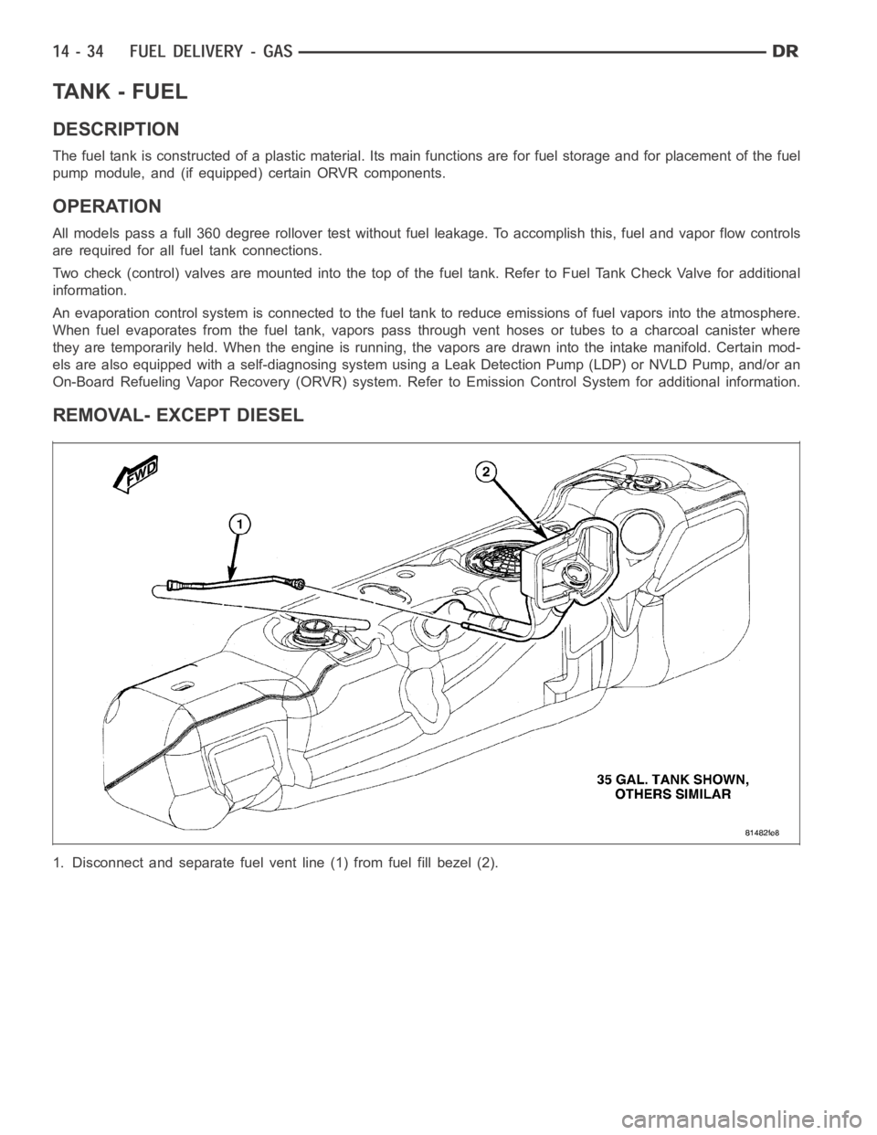
1. Disconnect and separate fuel vent line (1) from fuel fill bezel (2).
Page 2272 of 5267
Page 2273 of 5267
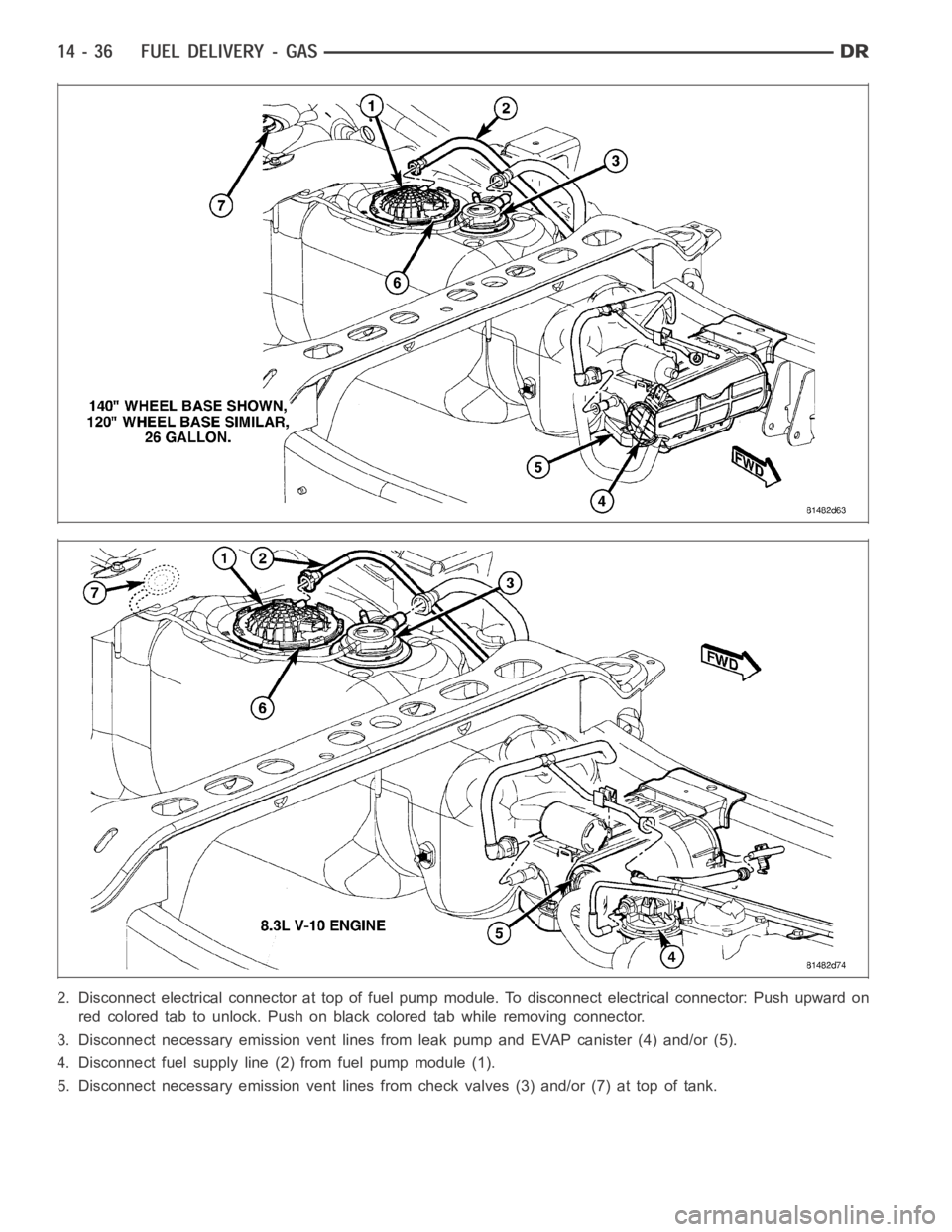
2. Disconnect electrical connector at top of fuel pump module. To disconnect electrical connector: Push upward on
red colored tab to unlock. Push on black colored tab while removing connector.
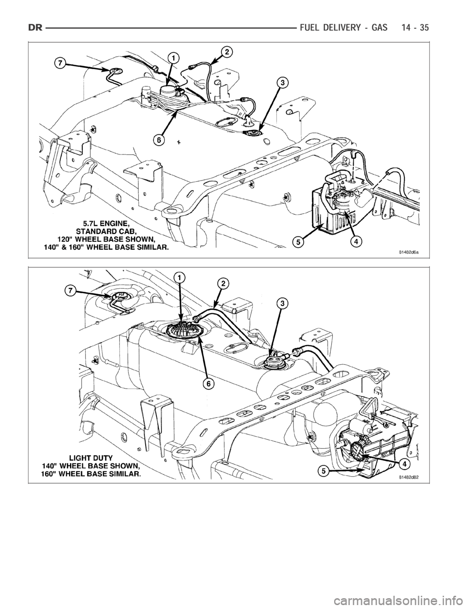
3. Disconnect necessary emission vent lines from leak pump and EVAP canister (4) and/or (5).
4. Disconnect fuel supply line (2) from fuel pump module (1).
5. Disconnect necessary emission vent lines from check valves (3) and/or (7) at top of tank.
Page 2274 of 5267
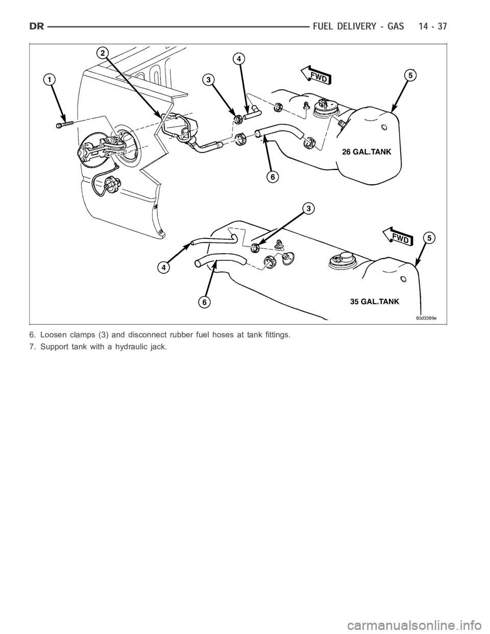
6. Loosen clamps (3) and disconnect rubber fuel hoses at tank fittings.
7. Support tank with a hydraulic jack.
Page 2275 of 5267
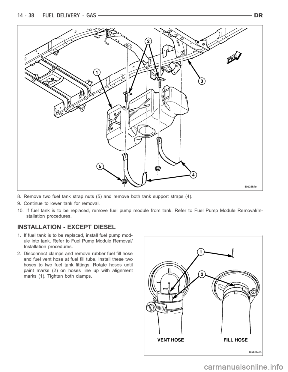
8. Remove two fuel tank strap nuts (5) and remove both tank support straps (4).
9. Continue to lower tank for removal.
10. If fuel tank is to be replaced, remove fuel pump module from tank. Refer to Fuel Pump Module Removal/In-
stallation procedures.
INSTALLATION - EXCEPT DIESEL
1. If fuel tank is to be replaced, install fuel pump mod-
ule into tank. Refer to Fuel Pump Module Removal/
Installation procedures.
2. Disconnect clamps and remove rubber fuel fill hose
and fuel vent hose at fuel fill tube. Install these two
hoses to two fuel tank fittings. Rotate hoses until
paint marks (2) on hoses line up with alignment
marks (1). Tighten both clamps.
Page 2276 of 5267
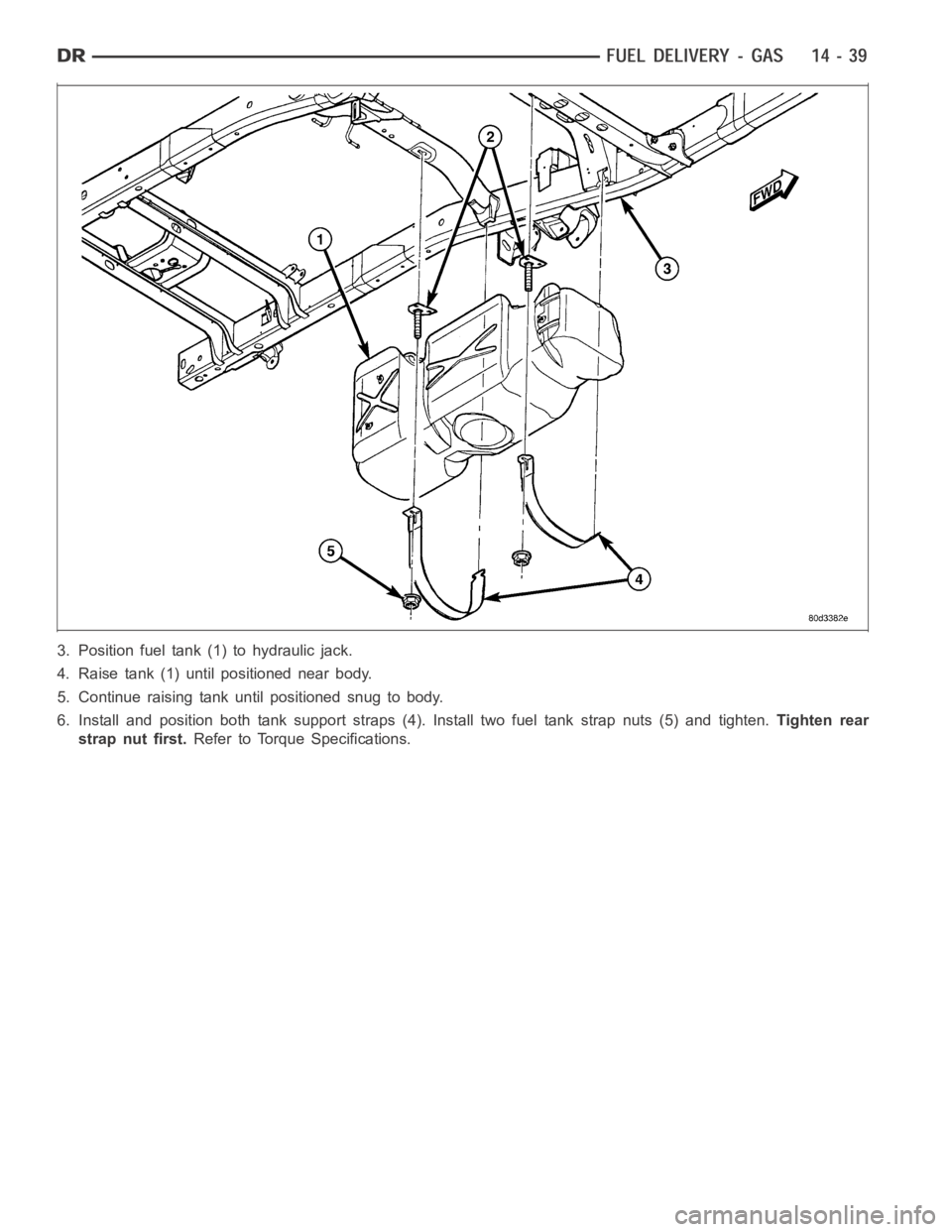
3. Position fuel tank (1) to hydraulic jack.
4. Raise tank (1) until positioned near body.
5. Continue raising tank until positioned snug to body.
6. Install and position both tank support straps (4). Install two fuel tankstrap nuts (5) and tighten.Tighten rear
strap nut first.Refer to Torque Specifications.
Page 2277 of 5267
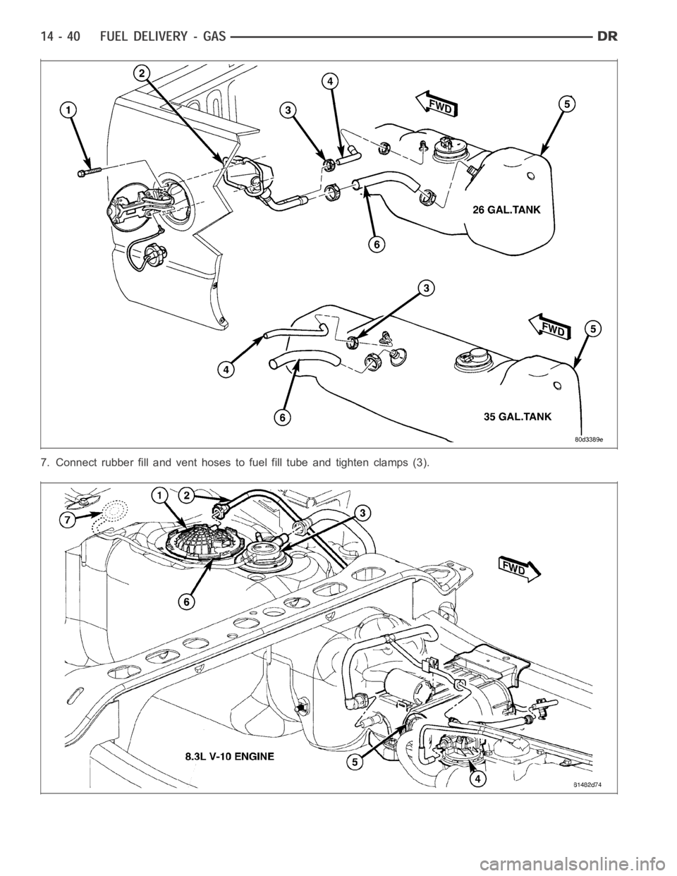
7. Connect rubber fill and vent hoses to fuel fill tube and tighten clamps (3).
Page 2278 of 5267
Page 2279 of 5267
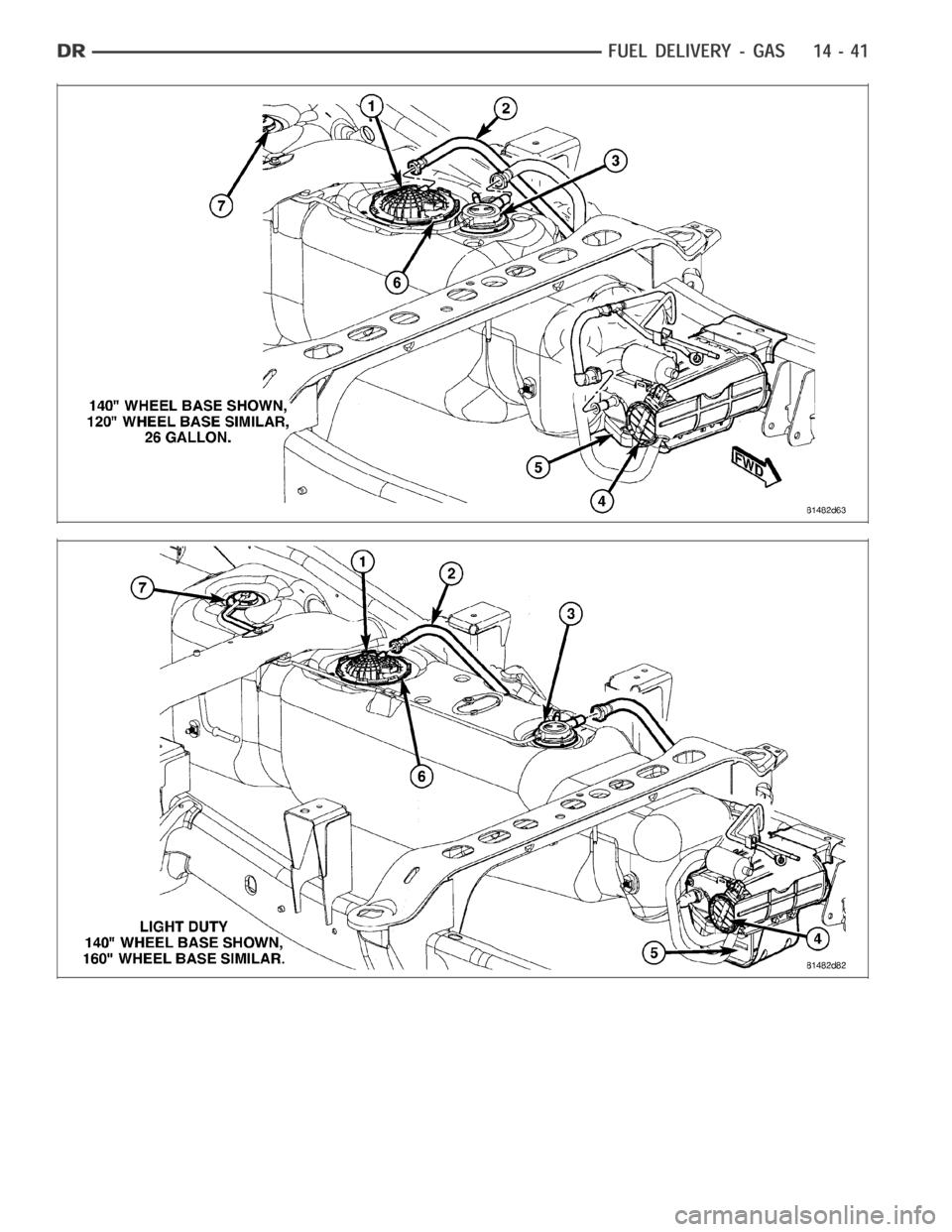
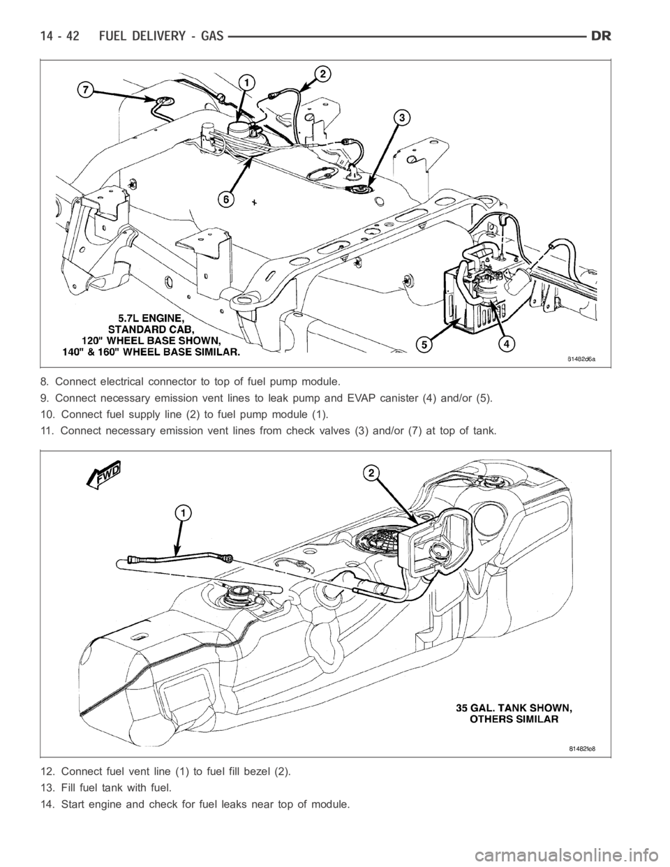
8. Connect electrical connector to top of fuel pump module.
9. Connect necessary emission vent lines to leak pump and EVAP canister (4)and/or (5).
10. Connect fuel supply line (2) to fuel pump module (1).
11. Connect necessary emission vent lines from check valves (3) and/or (7)at top of tank.
12. Connect fuel vent line (1) to fuel fill bezel (2).
13. Fill fuel tank with fuel.
14. Start engine and check for fuel leaks near top of module.
Page 2280 of 5267
FILTER - INLET
REMOVAL
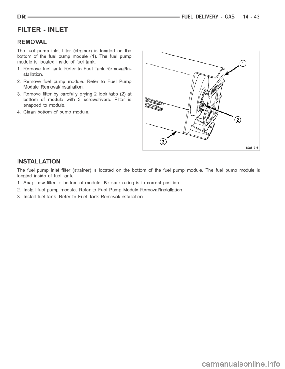
The fuel pump inlet filter (strainer) is located on the
bottom of the fuel pump module (1). The fuel pump
module is located inside of fuel tank.
1. Remove fuel tank. Refer to Fuel Tank Removal/In-
stallation.
2. Remove fuel pump module. Refer to Fuel Pump
Module Removal/Installation.
3. Remove filter by carefully prying 2 lock tabs (2) at
bottom of module with 2 screwdrivers. Filter is
snapped to module.
4. Clean bottom of pump module.
INSTALLATION
The fuel pump inlet filter (strainer) is located on the bottom of the fuel pump module. The fuel pump module is
located inside of fuel tank.
1. Snap new filter to bottom of module. Be sure o-ring is in correct position.
2. Install fuel pump module. Refer to Fuel Pump Module Removal/Installation.
3. Install fuel tank. Refer to Fuel Tank Removal/Installation.
Trending: overheating, tire size, oil dipstick, Leak, length, rims, battery

