clutch DODGE RAM SRT-10 2006 Service Owner's Manual
[x] Cancel search | Manufacturer: DODGE, Model Year: 2006, Model line: RAM SRT-10, Model: DODGE RAM SRT-10 2006Pages: 5267, PDF Size: 68.7 MB
Page 664 of 5267

4.(K160) DRIVER CIRCUIT SHORTED TO (K690) RETURN CIRCUIT
Measure the resistance between the fan clutch (K160) driver circuit and
the fan speed sensor (K690) return circuit at the sensor harness con-
nector.
Is the resistance greater than 100K Ohms?
Ye s>>
Go To 5
No>>
Repair the (K160) Driver circuit shorted to (K690) Return
circuit.
Perform POWERTRAIN VERIFICATION TEST VER - 1
(DIESEL). (Refer to 8 - ELECTRICAL/ELECTRONIC CON-
TROL MODULES/ENGINE CONTROL MODULE - DIAG-
NOSIS AND TESTING)
5.(K160) DRIVER CIRCUIT SHORTED TO BATTERY NEGATIVE
Measure the resistance between the fan clutch (K160) driver circuit and
the battery negative.
Is the resistance greater than 100k Ohms?
Ye s>>
Go To 6
No>>
Repair the (K160) Driver circuit shorted to battery negative.
Perform POWERTRAIN VERIFICATION TEST VER - 1
(DIESEL). (Refer to 8 - ELECTRICAL/ELECTRONIC CON-
TROL MODULES/ENGINE CONTROL MODULE - DIAG-
NOSIS AND TESTING)
Page 665 of 5267

6.ECM
Reconnect the ECM harness connectors.
Measure the resistance of the fan clutch (K160) driver circuit between
the fan clutch connector and battery negative.
Is the resistance greater than 100k Ohms?
Ye s>>
Refer to the INTERMITTENT CONDITION Symptom (Diag-
nostic Procedure). (Refer to 9 - ENGINE - DIAGNOSIS
AND TESTING)
No>>
replace the ECM.
Perform POWERTRAIN VERIFICATION TEST VER - 1
(DIESEL). (Refer to 8 - ELECTRICAL/ELECTRONIC CON-
TROL MODULES/ENGINE CONTROL MODULE - DIAG-
NOSIS AND TESTING)
Page 667 of 5267

When Monitored:
While the engine is running.
Set Condition:
The actual fan speed is less than 50 RPM or more than 6000 RPM.
Possible Causes
OTHER DTC’S
(K161) SIGNAL CIRCUIT SHORT TO (K668) 5-VOLT SUPPLY CIRCUIT
(K161) SIGNAL CIRCUIT OPEN FROM ECM TO FAN CLUTCH ASSEMBLY
(K668) 5-VOLT SUPPLY CKT OPEN FROM ECM HARNESS CONNECTOR TO FAN CLUTCH HARNESS
CONNECTOR
INTERMITTENT CONDITION
(K161) SIGNAL CIRCUIT SHORTED TO (690) RETURN IN THE HARNESS
(K161) SIGNAL CIRCUIT SHORTED TO VOLTAGE
(K161) SIGNAL CIRCUIT IN ECM SHORTED TO GROUND INSIDE ECM
(K161) SIGNAL CIRCUIT SHORTED TO VOLTAGE IN THE ECM
(K668) 5-VOLT SUPPLY CIRCUIT IN ECM
Always perform the Pre-Diagnostic Troubleshooting procedure before proceeding. (Refer to 9 - ENGINE -
DIAGNOSIS AND TESTING)
Diagnostic Test
1.OTHER DTC’S PRESENT
With the scan tool, read DTCs.
Is DTC P0480 present?
Ye s>>
Repair other DTC’s first.
Perform POWERTRAIN VERIFICATION TEST VER - 1 (DIESEL). (Refer to 8 - ELECTRICAL/ELEC-
TRONIC CONTROL MODULES/ENGINE CONTROL MODULE - DIAGNOSIS AND TESTING)
No>>
Go To 2
2.FA N C L U T C H S H O R T E D
Disconnect the wiring harness from the fan clutch assembly.
NOTE: Check connectors - Clean/repair as necessary.
Measure the resistance between the signal circuit in the fan clutch assembly and the return circuit in the fan clutch
assembly.
Is the resistance less than 10 Ohms?
Ye s>>
Replace the fan clutch assembly.
Perform POWERTRAIN VERIFICATION TEST VER - 1 (DIESEL). (Refer to 8 - ELECTRICAL/ELEC-
TRONIC CONTROL MODULES/ENGINE CONTROL MODULE - DIAGNOSIS AND TESTING)
No>>
Go To 3
Page 668 of 5267

3.FAN CLUTCH ASSEMBLEY SHORTED TO GROUND
Measure the resistance between the signal circuit in the fan clutch assembly and battery negative.
Is the resistance less than 10 Ohms?
Ye s>>
Replace the fan clutch assembly.
Perform POWERTRAIN VERIFICATION TEST VER - 1 (DIESEL). (Refer to 8 - ELECTRICAL/ELEC-
TRONIC CONTROL MODULES/ENGINE CONTROL MODULE - DIAGNOSIS AND TESTING)
No>>
Go To 4
4.(K161) SIGNAL CIRCUIT SHORT TO (K668) 5-VOLT SUPPLY CIRCUIT
Disconnect the Fan clutch connector.
NOTE: Check connectors - Clean/repair as necessary.
Measure the resistance between the (K161) signal circuit in the fan
clutch assembly and the battery (K668) 5-volt supply circuit in the fan
clutch assembly.
Is the resistance less than 10 Ohms?
Ye s>>
Replace the Fan clutch assembly.
Perform POWERTRAIN VERIFICATION TEST VER - 1
(DIESEL). (Refer to 8 - ELECTRICAL/ELECTRONIC CON-
TROL MODULES/ENGINE CONTROL MODULE - DIAG-
NOSIS AND TESTING)
No>>
Go To 5
Page 669 of 5267

5.(K161) SIGNAL CIRCUIT OPEN FROM ECM TO FAN CLUTCH ASSEMBLY
Disconnect the ECM harness connectors.
Check connectors - Clean/repair as necessary.
Measure the resistance of the (K161) signal circuit between the ECM
harness connector and the fan clutch assembly harness connector.
Is the resistance less than 10 Ohms?
Ye s>>
Go To 6
No>>
Repair the open (K161) circuit from the ECM harness con-
nector to the Fan clutch harness connector.
Perform POWERTRAIN VERIFICATION TEST VER - 1
(DIESEL). (Refer to 8 - ELECTRICAL/ELECTRONIC CON-
TROL MODULES/ENGINE CONTROL MODULE - DIAG-
NOSIS AND TESTING)
6.(K668) 5-VOLT SUPPLY CIRCUIT OPEN FROM ECM HARNESS CONNECTOR TO FAN CLUTCHHARNESS
Measure the resistance of the (K668) 5-volt supply circuit between the
ECM harness connector and the fan clutch assembly harness connec-
tor.
Is the resistance less than 10 Ohms?
Ye s>>
Go To 7
No>>
Repair the open (K668) circuit from ECM harness connector
to Fan clutch connector.
Perform POWERTRAIN VERIFICATION TEST VER - 1
(DIESEL). (Refer to 8 - ELECTRICAL/ELECTRONIC CON-
TROL MODULES/ENGINE CONTROL MODULE - DIAG-
NOSIS AND TESTING)
Page 670 of 5267

7.(K161) SIGNAL CIRCUIT SHORTED TO RETURN IN THE HARNESS
Measure the resistance between the (K161) signal circuit in the fan
clutch assembly harness connector and the return circuit in the fan
clutch assembly harness connector.
Is the resistance less than 10 Ohms?
Ye s>>
Repair the shorted (K161) circuit.
Perform POWERTRAIN VERIFICATION TEST VER - 1
(DIESEL). (Refer to 8 - ELECTRICAL/ELECTRONIC CON-
TROL MODULES/ENGINE CONTROL MODULE - DIAG-
NOSIS AND TESTING)
No>>
Go To 8
8.(K161) SIGNAL CIRCUIT SHORTED TO VOLTAGE
Measure the voltage between the (K161) signal circuit in the fan clutch
assembly harness connector and battery negative.
Is the voltage greater than 1 volt?
Ye s>>
Repair the (K161) signal circuit shorted to voltage.
Perform POWERTRAIN VERIFICATION TEST VER - 1
(DIESEL). (Refer to 8 - ELECTRICAL/ELECTRONIC CON-
TROL MODULES/ENGINE CONTROL MODULE - DIAG-
NOSIS AND TESTING)
No>>
Go To 9
Page 671 of 5267

9.(K161) SIGNAL CIRCUIT IN ECM SHORTED TO GROUND INSIDE ECM
Reconnect the ECM harness connectors.
Measure the resistance between the (K161) signal circuit in the fan
clutch assembly harness connector and battery negative.
Is the resistance less than 10 Ohms?
Ye s>>
Replace the ECM.
Perform POWERTRAIN VERIFICATION TEST VER - 1
(DIESEL). (Refer to 8 - ELECTRICAL/ELECTRONIC CON-
TROL MODULES/ENGINE CONTROL MODULE - DIAG-
NOSIS AND TESTING)
No>>
Go To 10
10.(K161) SIGNAL CIRCUIT SHORTED TO VOLTAGE IN THE ECM
Reconnect the fan harness connector.
Turn the ignition on.
While back probing the fan connector measure the voltage between the
fan speed (K161) signal circuit in the fan clutch assembly harness con-
nector and battery negative while manually rotating the fan blade.
Did voltage go from less than 0.7 volts to 4.5 to 5.5 volts?
Ye s>>
Repair the Fan Speed (K161) Signal circuit in the engine
harness.
Perform POWERTRAIN VERIFICATION TEST VER - 1
(DIESEL). (Refer to 8 - ELECTRICAL/ELECTRONIC CON-
TROL MODULES/ENGINE CONTROL MODULE - DIAG-
NOSIS AND TESTING)
No>>
Go To 11
Page 672 of 5267

11 .(K668) 5-VOLT SUPPLY CIRCUIT IN ECM
Turn the ignition on.
Measure the voltage between the (K668) 5-volt supply circuit in the fan
clutch assembly harness connector and battery negative.
Is the voltage between 4.5 and 5.5 volts?
Ye s>>
Refer to the INTERMITTENT CONDITION Symptom (Diag-
nostic Procedure). (Refer to 9 - ENGINE - DIAGNOSIS
AND TESTING)
No>>
Replace the ECM.
Perform POWERTRAIN VERIFICATION TEST VER - 1
(DIESEL). (Refer to 8 - ELECTRICAL/ELECTRONIC CON-
TROL MODULES/ENGINE CONTROL MODULE - DIAG-
NOSIS AND TESTING)
Page 751 of 5267
When Monitored:
With the key on.
Set Condition:
Voltage detected on the #2 sensor supply circuit is below a calibrated value.
Possible Causes
FAN CLUTCH ASSEMBLY
(K668) 5-VOLT SHORTED TO GROUND
(K668) 5-VOLT SUPPLY SHORTED TO ANOTHER CIRCUIT
FA N D T C
INTERMITTENT CONDITION
ECM
Always perform the Pre-Diagnostic Troubleshooting procedure before proceeding. (Refer to 9 - ENGINE -
DIAGNOSIS AND TESTING)
Diagnostic Test
1.FAN CLUTCH ASSEMBLY
Disconnect the Fan clutch harness connector.
NOTE: Check connectors - Clean/repair as necessary.
With the scan tool, read DTCs.
Did P0483 set?
Ye s>>
Replace the Fan clutch assembly.
Perform POWERTRAIN VERIFICATION TEST VER - 1 (DIESEL). (Refer to 8 - ELECTRICAL/ELEC-
TRONIC CONTROL MODULES/ENGINE CONTROL MODULE - DIAGNOSIS AND TESTING)
No>>
Go To 2
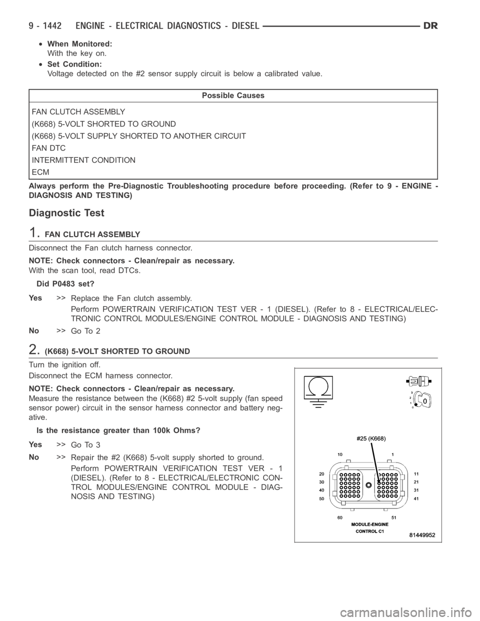
2.(K668) 5-VOLT SHORTED TO GROUND
Turn the ignition off.
Disconnect the ECM harness connector.
NOTE: Check connectors - Clean/repair as necessary.
Measure the resistance between the (K668) #2 5-volt supply (fan speed
sensor power) circuit in the sensor harness connector and battery neg-
ative.
Is the resistance greater than 100k Ohms?
Ye s>>
Go To 3
No>>
Repair the #2 (K668) 5-volt supply shorted to ground.
Perform POWERTRAIN VERIFICATION TEST VER - 1
(DIESEL). (Refer to 8 - ELECTRICAL/ELECTRONIC CON-
TROL MODULES/ENGINE CONTROL MODULE - DIAG-
NOSIS AND TESTING)
Page 753 of 5267
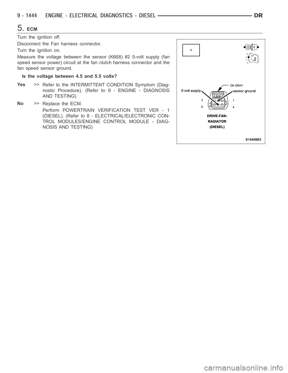
5.ECM
Turn the ignition off.
Disconnect the Fan harness connector.
Turn the ignition on.
Measure the voltage between the sensor (K668) #2 5-volt supply (fan
speed sensor power) circuit at the fan clutch harness connector and the
fan speed sensor ground.
Is the voltage between 4.5 and 5.5 volts?
Ye s>>
Refer to the INTERMITTENT CONDITION Symptom (Diag-
nostic Procedure). (Refer to 9 - ENGINE - DIAGNOSIS
AND TESTING)
No>>
Replace the ECM.
Perform POWERTRAIN VERIFICATION TEST VER - 1
(DIESEL). (Refer to 8 - ELECTRICAL/ELECTRONIC CON-
TROL MODULES/ENGINE CONTROL MODULE - DIAG-
NOSIS AND TESTING)