trailer DODGE RAM SRT-10 2006 Service Repair Manual
[x] Cancel search | Manufacturer: DODGE, Model Year: 2006, Model line: RAM SRT-10, Model: DODGE RAM SRT-10 2006Pages: 5267, PDF Size: 68.7 MB
Page 2174 of 5267
FRAME & BUMPERS
TABLE OF CONTENTS
page page
FRAMES & BUMPERS
SPECIFICATIONS
TORQUE .................................... 2
FRONT AIR DAM
REMOVAL ..................................... 3
INSTALLATION ................................ 3
FRONT BUMPER
REMOVAL ..................................... 4
INSTALLATION ................................ 4
FRONT FASCIA
REMOVAL ..................................... 5
INSTALLATION ................................ 6
REAR BUMPER
REMOVAL ..................................... 7
INSTALLATION ................................ 8
FASCIA-FRONT SRT-10
REMOVAL ..................................... 9
INSTALLATION ................................ 11
FASCIA-REAR SRT-10
REMOVAL .................................... 14
INSTALLATION ............................... 15
FRAME
WARNING
WARNINGS ................................ 17
STANDARD PROCEDURE
HYDROFORM FENDER RAIL REPAIR ........ 18REAR FRAME H-SECTION REPLACEMENT . . . 27
SPECIFICATIONS
WELD PROCESS ........................... 33
FRAME DIMENSIONS ....................... 34
TORQUE ................................... 45
FRONT CROSSMEMBER
REMOVAL .................................... 46
INSTALLATION ............................... 48
FRONT SKID PLATE
REMOVAL .................................... 50
INSTALLATION ............................... 51
FRONT TOW HOOK ASSEMBLY
REMOVAL .................................... 52
INSTALLATION ............................... 53
TRANSMISSION CROSSMEMBER
REMOVAL .................................... 54
INSTALLATION ............................... 56
TRAILER HITCH
REMOVAL .................................... 58
INSTALLATION ............................... 60
TRANSFER CASE SKID PLATE
REMOVAL .................................... 62
INSTALLATION ............................... 63
Page 2180 of 5267
REAR BUMPER
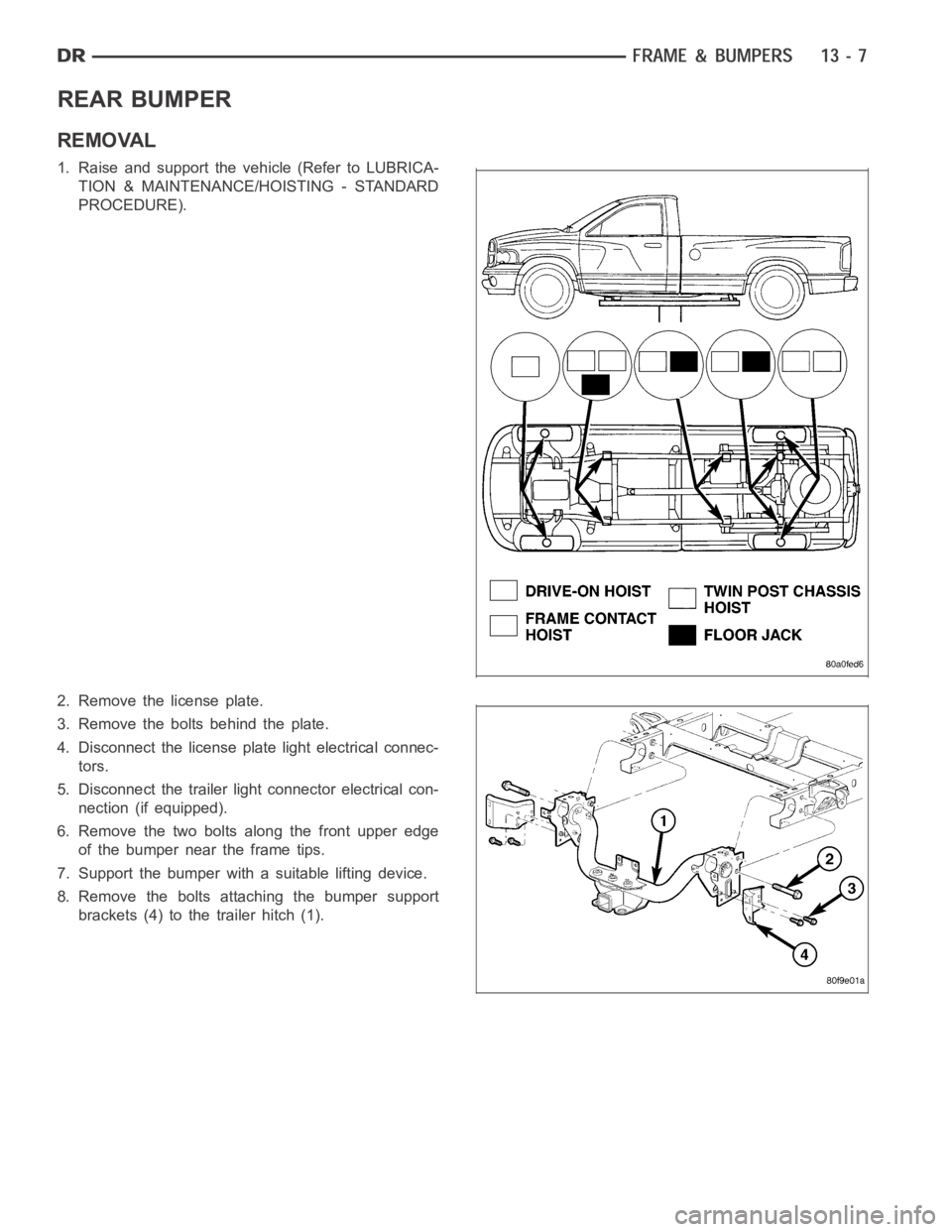
REMOVAL
1. Raise and support the vehicle (Refer to LUBRICA-
TION & MAINTENANCE/HOISTING - STANDARD
PROCEDURE).
2. Remove the license plate.
3. Remove the bolts behind the plate.
4. Disconnect the license plate light electrical connec-
tors.
5. Disconnect the trailer light connector electrical con-
nection (if equipped).
6. Remove the two bolts along the front upper edge
of the bumper near the frame tips.
7. Support the bumper with a suitable lifting device.
8. Remove the bolts attaching the bumper support
brackets (4) to the trailer hitch (1).
Page 2181 of 5267
INSTALLATION
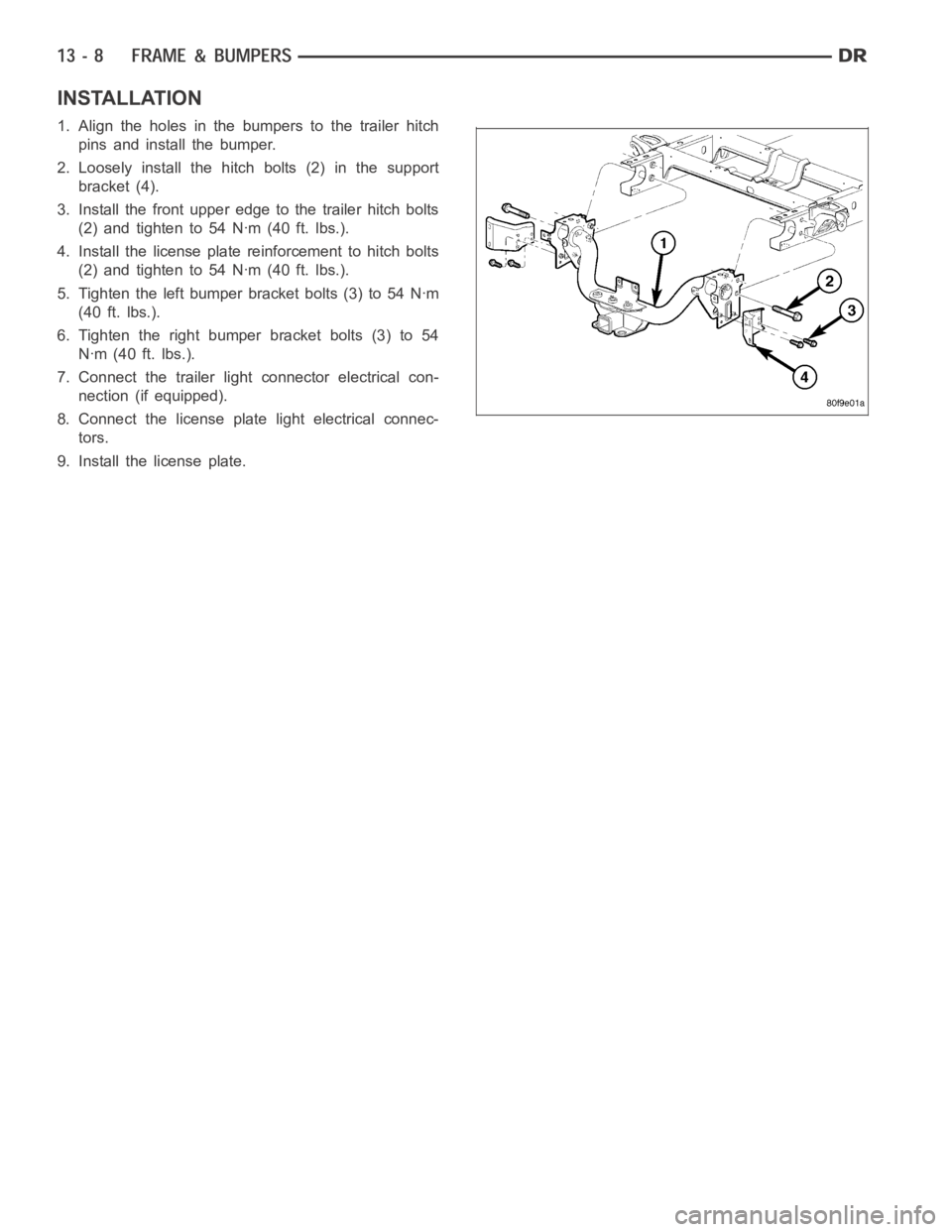
1. Align the holes in the bumpers to the trailer hitch
pins and install the bumper.
2. Loosely install the hitch bolts (2) in the support
bracket (4).
3. Install the front upper edge to the trailer hitch bolts
(2)andtightento54Nꞏm(40ft.lbs.).
4. Install the license plate reinforcement to hitch bolts
(2)andtightento54Nꞏm(40ft.lbs.).
5. Tighten the left bumper bracket bolts (3) to 54 Nꞏm
(40 ft. lbs.).
6. Tighten the right bumper bracket bolts (3) to 54
Nꞏm (40 ft. lbs.).
7. Connect the trailer light connector electrical con-
nection (if equipped).
8. Connect the license plate light electrical connec-
tors.
9. Install the license plate.
Page 2201 of 5267
2. Disconnect and isolate the battery negative cable.
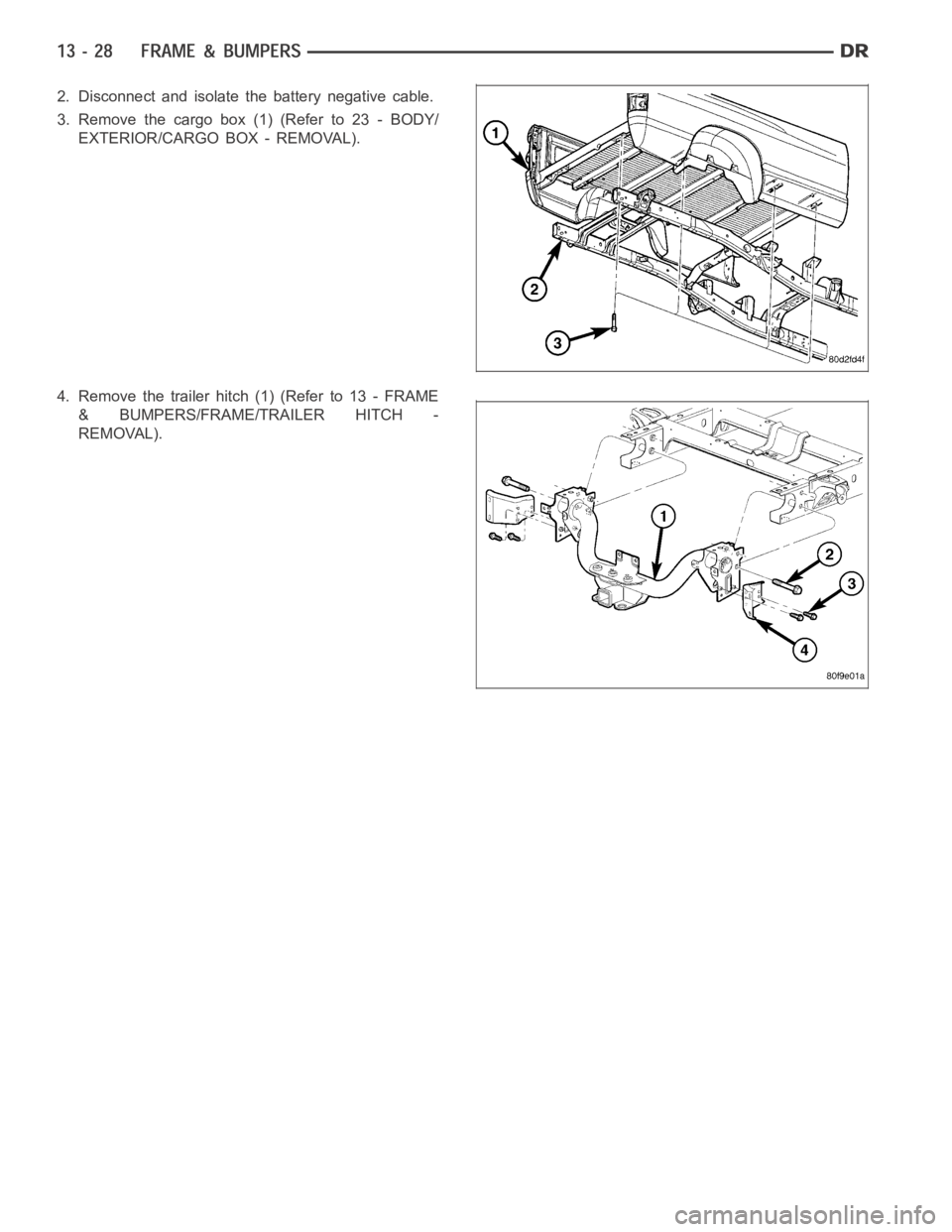
3. Remove the cargo box (1) (Refer to 23 - BODY/
EXTERIOR/CARGO BOX - REMOVAL).
4. Removethetrailerhitch(1)(Referto13-FRAME
& BUMPERS/FRAME/TRAILER HITCH -
REMOVAL).
Page 2205 of 5267
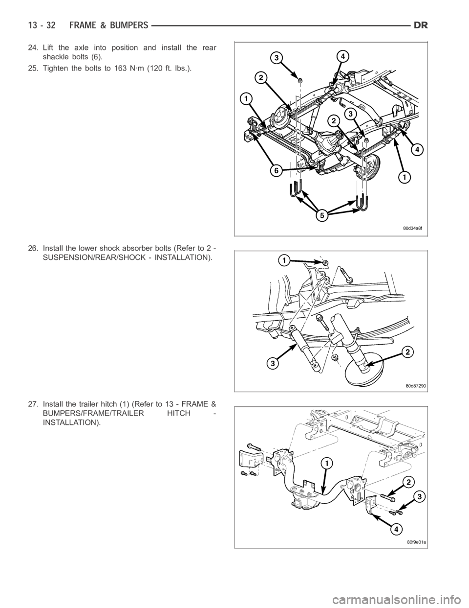
24. Lift the axle into position and install the rear
shackle bolts (6).
25. Tighten the bolts to 163 Nꞏm (120 ft. lbs.).
26. Install the lower shock absorber bolts (Refer to 2 -
SUSPENSION/REAR/SHOCK - INSTALLATION).
27. Install the trailer hitch (1) (Refer to 13 - FRAME &
BUMPERS/FRAME/TRAILER HITCH -
INSTALLATION).
Page 2218 of 5267
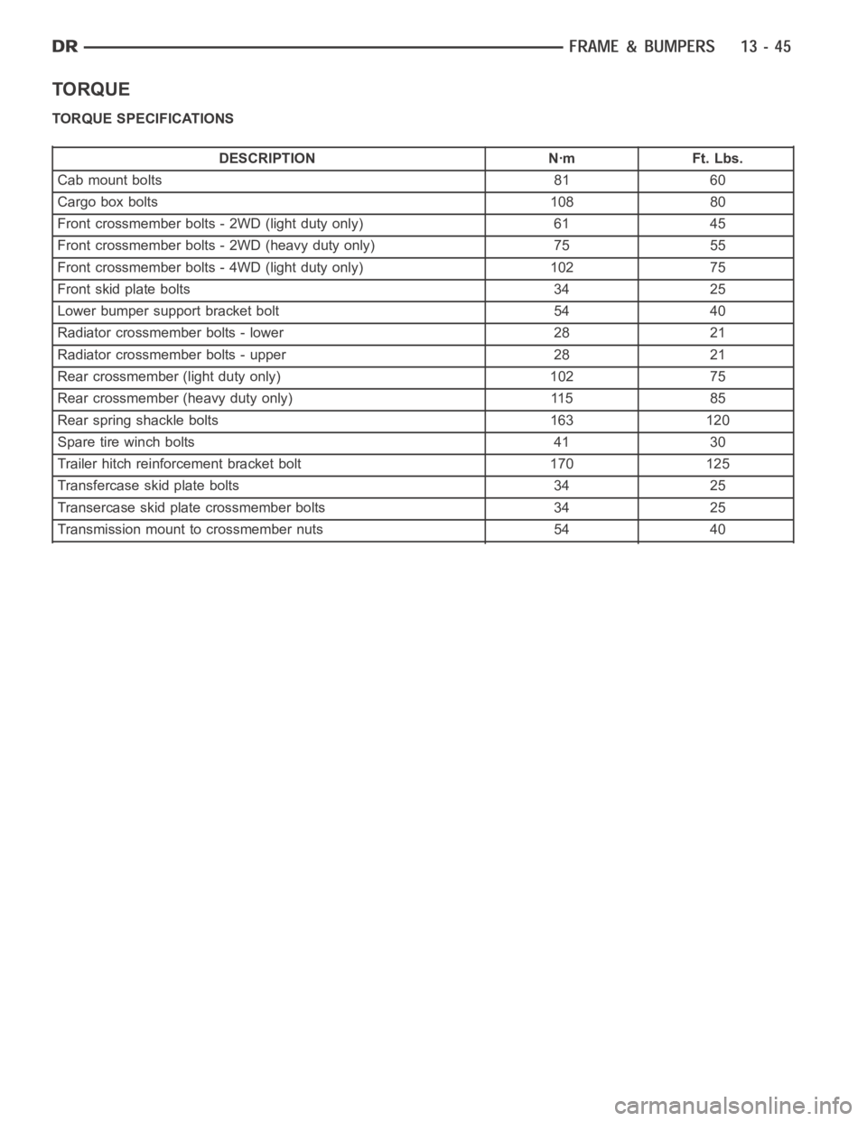
TORQUE
TORQUE SPECIFICATIONS
DESCRIPTION Nꞏm Ft. Lbs.
Cab mount bolts 81 60
Cargo box bolts 108 80
Front crossmember bolts - 2WD (light duty only) 61 45
Front crossmember bolts - 2WD (heavy duty only) 75 55
Front crossmember bolts - 4WD (light duty only) 102 75
Front skid plate bolts 34 25
Lower bumper support bracket bolt 54 40
Radiator crossmember bolts - lower 28 21
Radiator crossmember bolts - upper 28 21
Rear crossmember (light duty only) 102 75
Rear crossmember (heavy duty only) 115 85
Rear spring shackle bolts 163 120
Sparetirewinchbolts 41 30
Trailer hitch reinforcement bracket bolt 170 125
Transfercase skid plate bolts 34 25
Transercase skid plate crossmember bolts 34 25
Transmission mount to crossmember nuts 54 40
Page 2231 of 5267
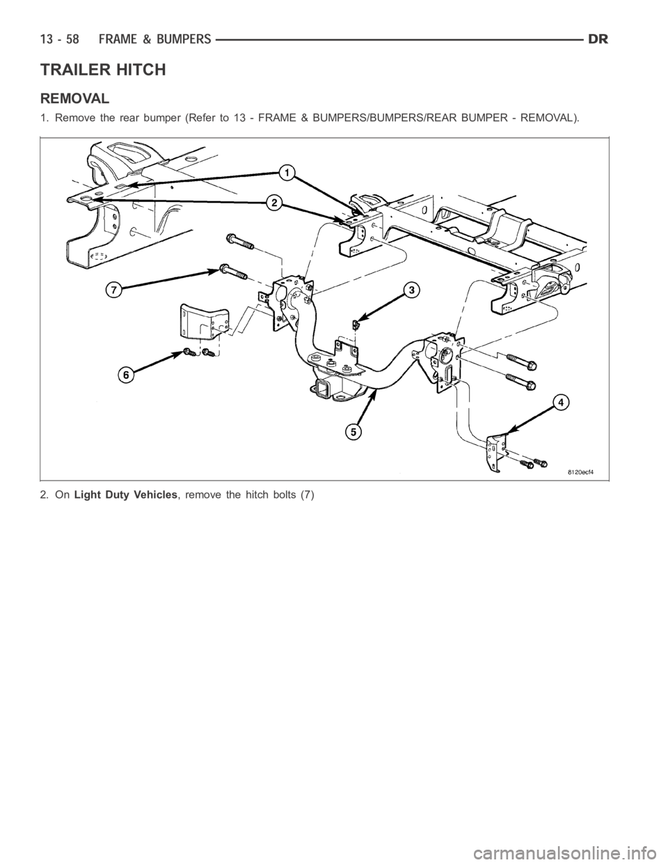
TRAILER HITCH
REMOVAL
1. Remove the rear bumper (Refer to 13 -FRAME & BUMPERS/BUMPERS/REAR BUMPER-REMOVAL).
2. OnLight Duty Vehicles, remove the hitch bolts (7)
Page 2732 of 5267
P0218-HIGH TEMPERATURE OPERATION ACTIVATED
For a complete wiring diagramRefer to Section 8W.
When Monitored:
Whenever the engine is running.
Set Condition:
Immediately when a Overheat shift schedule is activated when the Transmission Oil Temperature reaches 155°
C or 240° F.
Possible Causes
ENGINE COOLING SYSTEM OPERATION
TRANSMISSION OIL COOLER PLUGGED
H I G H T E M P E R AT U R E O P E R AT I O N S A C T I VAT E D
Always perform the Pre-Diagnostic Troubleshooting procedure before proceeding. (Refer to 21 - TRANSMIS-
SION/TRANSAXLE/AUTOMATIC - 42RLE - STANDARD PROCEDURE)
Theory of Operation
If the transmission oil temperature rises above 115° C (240° F), the overheat shift schedule is activated refer to
Transmission Operation as a function of Transmission Oil Temperature andthe code is set. The DTC is an infor-
mational code only and is being set to aid the technician in determining root cause of a customer driveability issue.
The code is also intended to alert the technician to determine if a cooling system malfunction has occurred or if an
additional transmission air to oil cooler should be added to the vehicle ifthe customer regularly drives in a manner
that overheats the transmission. Extended operation above 115° C (240° F)will reduce the durability of the trans-
mission and should be avoided. Correcting the cooling system malfunctionor installing an additional transmission oil
cooler will improve transmission durability especially for customers who operate in city/construction stop and go traf-
fic, tow trailers regularly, drive aggressively in low gear or drive regularly in mountainous areas.
Diagnostic Test
1.CHECK ENGINE COOLING SYSTEM
Perform Engine Cooling System diagnostics per the Service Information.
Is the Engine Cooling System functioning properly?
Ye s>>
Go To 2
No>>
Repair the cause of the engine overheating. Refer to the Service Information for the related diagnostic
or repair procedures.
Perform 42RLE TRANSMISSION VERIFICATION TEST - VER 1. (Refer to 21 - TRANSMISSION/
TRANSAXLE/AUTOMATIC - 42RLE - STANDARD PROCEDURE)
2.TRANSMISSION OIL COOLER RESTRICTED
Check the Transmission Oil Cooler Flow in accordance with the Service Information.
Is the transmission oil cooler restricted or plugged?
Ye s>>
Go To 3
No>>
Repair the cause of the plugged Transmission Oil Cooler as necessary and repair or replace the Trans-
mission Oil Cooler per the Service Information.
Perform 42RLE TRANSMISSION VERIFICATION TEST - VER 1. (Refer to 21 - TRANSMISSION/
TRANSAXLE/AUTOMATIC - 42RLE - STANDARD PROCEDURE)
Page 2899 of 5267
P1797-MANUAL SHIFT OVERHEAT
For a complete wiring diagramRefer to Section 8W.
When Monitored:
Continuously with engine running.
Set Condition:
If the Engine Temperature exceeds 123° C (255° F) or the Transmission Temperature exceeds 135° C (275° F)
while in AutoStick
mode. Note: Aggressive driving or driving in low for extended periods of time will set this
DTC.
Possible Causes
MANUAL SHIFT OVERHEAT
Always perform the 42RLE Pre-Diagnostic Troubleshooting procedure before proceeding. (Refer to 21 -
TRANSMISSION/TRANSAXLE/AUTOMATIC - 42RLE - STANDARD PROCEDURE)
Theory of Operation
The major cause of heat build up in the transmission is torque converter slip.WiththetransmissionintheAuto-
Stick
mode, the torque converter can slip during aggressive driving or heavy loading conditions such as trailer
towing or driving up steep grades. In the non AutoStick
mode, internal controller logic prevents the transmission
from overheating by managing the shift and EMCC schedule. In the AutoStick
mode, when the transmission or
engine temperature approaches an overheat condition, the manual shift overheat DTC sets and the AutoStick
mode is temporarily suspended until the temperature returns to normal.
Diagnostic Test
1.MANUAL SHIFT OVERHEAT
This is an informational DTC only.
With the scan tool, check the DTC EVENT DATA to help identify the conditionsin which the DTC was set.
Check the engine and transmission cooling system for proper operation.
Check the Radiator Cooling Fan operation.
Check the Transmission Cooling operation.
Check the Transmission Fluid Level per the Service Information to verify that it is not overfilled.
NOTE: Aggressive driving or driving in low for extended periods of time will set this DTC.
If there are no possible causes remaining, view repair.
Repair
If the Transmission Fluid is low, repair any Transmission Fluid leak as necessary and adjust the Trans-
mission Fluid Level per the Service Information. Refer to Service Information for the related symptoms
and repair as necessary.
Perform 42RLE TRANSMISSION VERIFICATION TEST - VER 1. (Refer to 21 - TRANSMISSION/
TRANSAXLE/AUTOMATIC - 42RLE - STANDARD PROCEDURE)
Page 3014 of 5267
FLUID AND FILTER
DIAGNOSIS AND TESTING
CAUSES OF BURNT FLUID
Burnt, discolored fluid is a result of overheating which has two primary causes.
1. A result of restricted fluid flow through the main and/or auxiliary cooler. This condition is usually the result of a
faulty or improperly installed drainback valve, a damaged oil cooler, or severe restrictions in the coolers and lines
caused by debris or kinked lines.
2. Heavy duty operation with a vehicle not properly equipped for this type of operation. Trailer towing or similar high
load operation will overheat the transmission fluid if the vehicle is improperly equipped. Such vehicles should
have an auxiliary transmission fluid cooler, a heavy duty cooling system,and the engine/axle ratio combination
needed to handle heavy loads.
EFFECTS OF INCORRECT FLUID LEVEL
Alowfluidlevelallowsthepumptotakeinairalongwiththefluid.Airinthe fluid will cause fluid pressures to be
low and develop slower than normal. If the transmission is overfilled, thegears churn the fluid into foam. This aer-
ates the fluid and causing the same conditions occurring with a low level. In either case, air bubbles cause fluid
overheating, oxidation, and varnish buildup which interferes with valveand clutch operation. Foaming also causes
fluid expansion which can result in fluid overflow from the transmission vent or fill tube. Fluid overflow can easily be
mistaken for a leak if inspection is not careful.
FLUID CONTAMINATION
Transmission fluid contamination is generally a result of:
adding incorrect fluid
failure to clean dipstick and fill tube when checking level
engine coolant entering the fluid
internal failure that generates debris
overheat that generates sludge (fluid breakdown)
failure to replace contaminated converter after repair
The use of non-recommended fluids can result in transmission failure. Theusual results are erratic shifts, slippage,
abnormal wear and eventual failure due to fluid breakdown and sludge formation. Avoid this condition by using rec-
ommended fluids only.
The dipstick cap and fill tube should be wiped clean before checking fluid level. Dirt, grease and other foreign mate-
rial on the cap and tube could fall into the tube if not removed beforehand. Take the time to wipe the cap and tube
clean before withdrawing the dipstick.
Engine coolant in the transmission fluid is generally caused by a cooler malfunction. The only remedy is to replace
the radiator as the cooler in the radiator is not a serviceable part. If coolant has circulated through the transmission,
an overhaul is necessary.
The torque converter should also be replaced whenever a failure generatessludge and debris. This is necessary
because normal converter flushing procedures will not remove all contaminants.
STANDARD PROCEDURE
FLUID LEVEL CHECK
The transmission sump has a dipstick to check oil similar to most automatictransmissions. It is located on the left
side of the engine. Be sure to wipe all dirt from dipstick handle before removing.
The torque converter fills in both the PARK and NEUTRAL positions. Place the selector lever in PARK to be sure
that the fluid level check is accurate.The engine should be running at idle speed for at least one minute, with
the vehicle on level ground.At normal operating temperature (approximately 82° C or 180° F), the fluidlevel is
correct if it is in the HOT region (cross-hatched area) on the oil level indicator. The fluid level should be in COLD
region at 21° C (70° F) fluid temperature. Adjust fluid level as necessary.Use only Mopar
ATF+4, Automatic Trans-
mission Fluid.