fuel pressure DODGE RAM SRT-10 2006 Service Owner's Manual
[x] Cancel search | Manufacturer: DODGE, Model Year: 2006, Model line: RAM SRT-10, Model: DODGE RAM SRT-10 2006Pages: 5267, PDF Size: 68.7 MB
Page 532 of 5267
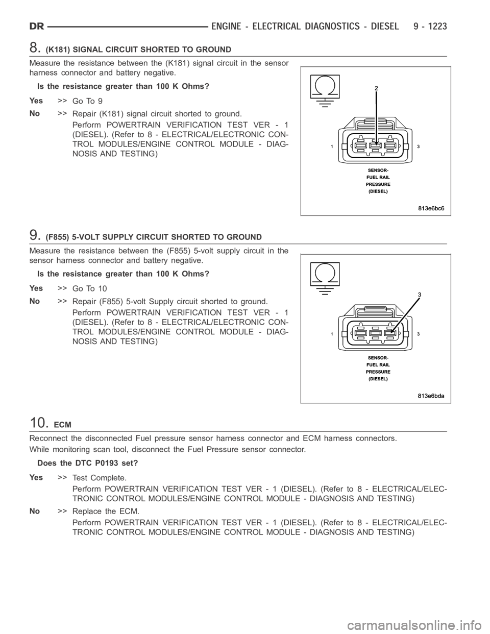
8.(K181) SIGNAL CIRCUIT SHORTED TO GROUND
Measure the resistance between the (K181) signal circuit in the sensor
harness connector and battery negative.
Is the resistance greater than 100 K Ohms?
Ye s>>
Go To 9
No>>
Repair (K181) signal circuit shorted to ground.
Perform POWERTRAIN VERIFICATION TEST VER - 1
(DIESEL). (Refer to 8 - ELECTRICAL/ELECTRONIC CON-
TROL MODULES/ENGINE CONTROL MODULE - DIAG-
NOSIS AND TESTING)
9.(F855) 5-VOLT SUPPLY CIRCUIT SHORTED TO GROUND
Measure the resistance between the (F855) 5-volt supply circuit in the
sensor harness connector and battery negative.
Is the resistance greater than 100 K Ohms?
Ye s>>
Go To 10
No>>
Repair (F855) 5-volt Supply circuit shorted to ground.
Perform POWERTRAIN VERIFICATION TEST VER - 1
(DIESEL). (Refer to 8 - ELECTRICAL/ELECTRONIC CON-
TROL MODULES/ENGINE CONTROL MODULE - DIAG-
NOSIS AND TESTING)
10.ECM
Reconnect the disconnected Fuel pressure sensor harness connector and ECM harness connectors.
While monitoring scan tool, disconnect the Fuel Pressure sensor connector.
Does the DTC P0193 set?
Ye s>>
Te s t C o m p l e t e .
Perform POWERTRAIN VERIFICATION TEST VER - 1 (DIESEL). (Refer to 8 - ELECTRICAL/ELEC-
TRONIC CONTROL MODULES/ENGINE CONTROL MODULE - DIAGNOSIS AND TESTING)
No>>
Replace the ECM.
Perform POWERTRAIN VERIFICATION TEST VER - 1 (DIESEL). (Refer to 8 - ELECTRICAL/ELEC-
TRONIC CONTROL MODULES/ENGINE CONTROL MODULE - DIAGNOSIS AND TESTING)
Page 533 of 5267
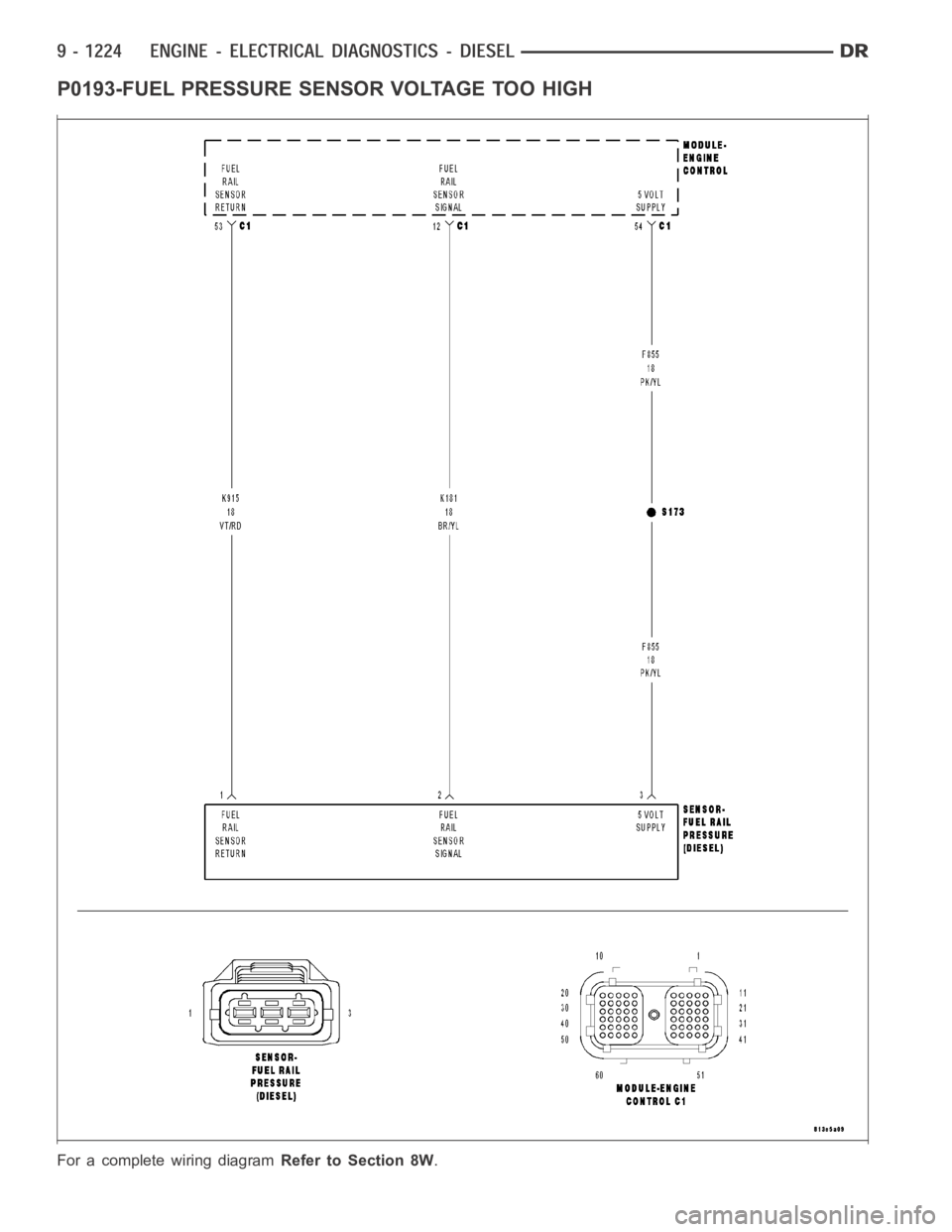
P0193-FUEL PRESSURE SENSOR VOLTAGE TOO HIGH
For a complete wiring diagramRefer to Section 8W.
Page 534 of 5267
When Monitored:
With the ignition on and battery voltage greater than 10.4 volts.
Set Condition:
The circuit voltage to the ECM is above a calibrated threshold for a certainperiod of time.
Possible Causes
OTHER DTC’S
FUEL PRESSURE SENSOR
(K181) SIGNAL CIRCUIT SHORTED TO VOLTAGE
(F855) 5-VOLT SUPPLY CIRCUIT SHORTED TO VOLTAGE
(K181) SIGNAL CIRCUIT SHORTED TO (F855) 5-VOLT SUPPLY CIRCUIT
(K915) RETURN CIRCUIT OPEN
ECM
INTERMITTENT CONDITION
Always perform the Pre-Diagnostic Troubleshooting procedure before proceeding. (Refer to 9 - ENGINE -
DIAGNOSIS AND TESTING)
Diagnostic Test
1.OTHER DTC’S
Ignition on, engine not running.
With the scan tool, read DTCs.
Do you have multiple DTC’s?
Ye s>>
Refer to multiple fault troubleshooting tree.
Perform POWERTRAIN VERIFICATION TEST VER - 1 (DIESEL). (Refer to 8 - ELECTRICAL/ELEC-
TRONIC CONTROL MODULES/ENGINE CONTROL MODULE - DIAGNOSIS AND TESTING)
No>>
Go To 2
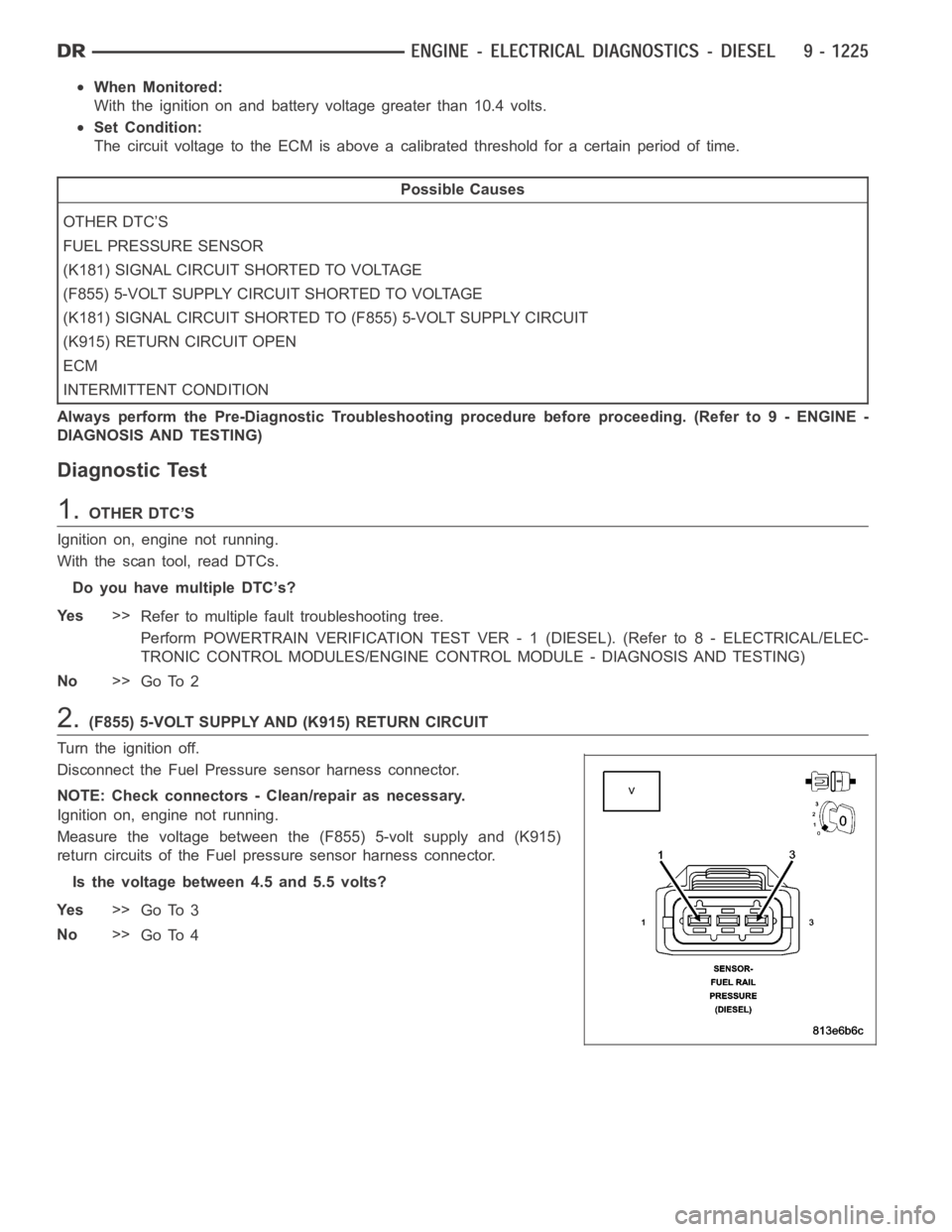
2.(F855) 5-VOLT SUPPLY AND (K915) RETURN CIRCUIT
Turn the ignition off.
Disconnect the Fuel Pressure sensor harness connector.
NOTE: Check connectors - Clean/repair as necessary.
Ignition on, engine not running.
Measure the voltage between the (F855) 5-volt supply and (K915)
return circuits of the Fuel pressure sensor harness connector.
Is the voltage between 4.5 and 5.5 volts?
Ye s>>
Go To 3
No>>
Go To 4
Page 535 of 5267
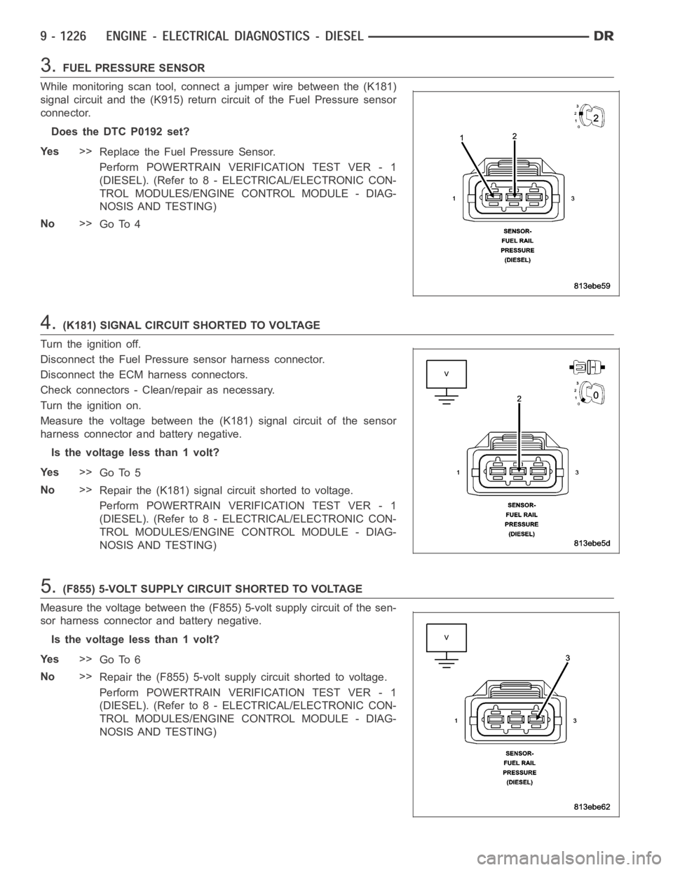
3.FUEL PRESSURE SENSOR
While monitoring scan tool, connect a jumper wire between the (K181)
signal circuit and the (K915) return circuit of the Fuel Pressure sensor
connector.
Does the DTC P0192 set?
Ye s>>
Replace the Fuel Pressure Sensor.
Perform POWERTRAIN VERIFICATION TEST VER - 1
(DIESEL). (Refer to 8 - ELECTRICAL/ELECTRONIC CON-
TROL MODULES/ENGINE CONTROL MODULE - DIAG-
NOSIS AND TESTING)
No>>
Go To 4
4.(K181) SIGNAL CIRCUIT SHORTED TO VOLTAGE
Turn the ignition off.
Disconnect the Fuel Pressure sensor harness connector.
Disconnect the ECM harness connectors.
Check connectors - Clean/repair as necessary.
Turn the ignition on.
Measure the voltage between the (K181) signal circuit of the sensor
harness connector and battery negative.
Is the voltage less than 1 volt?
Ye s>>
Go To 5
No>>
Repair the (K181) signal circuit shorted to voltage.
Perform POWERTRAIN VERIFICATION TEST VER - 1
(DIESEL). (Refer to 8 - ELECTRICAL/ELECTRONIC CON-
TROL MODULES/ENGINE CONTROL MODULE - DIAG-
NOSIS AND TESTING)
5.(F855) 5-VOLT SUPPLY CIRCUIT SHORTED TO VOLTAGE
Measure the voltage between the (F855) 5-volt supply circuit of the sen-
sor harness connector and battery negative.
Is the voltage less than 1 volt?
Ye s>>
Go To 6
No>>
Repair the (F855) 5-volt supply circuit shorted to voltage.
Perform POWERTRAIN VERIFICATION TEST VER - 1
(DIESEL). (Refer to 8 - ELECTRICAL/ELECTRONIC CON-
TROL MODULES/ENGINE CONTROL MODULE - DIAG-
NOSIS AND TESTING)
Page 595 of 5267
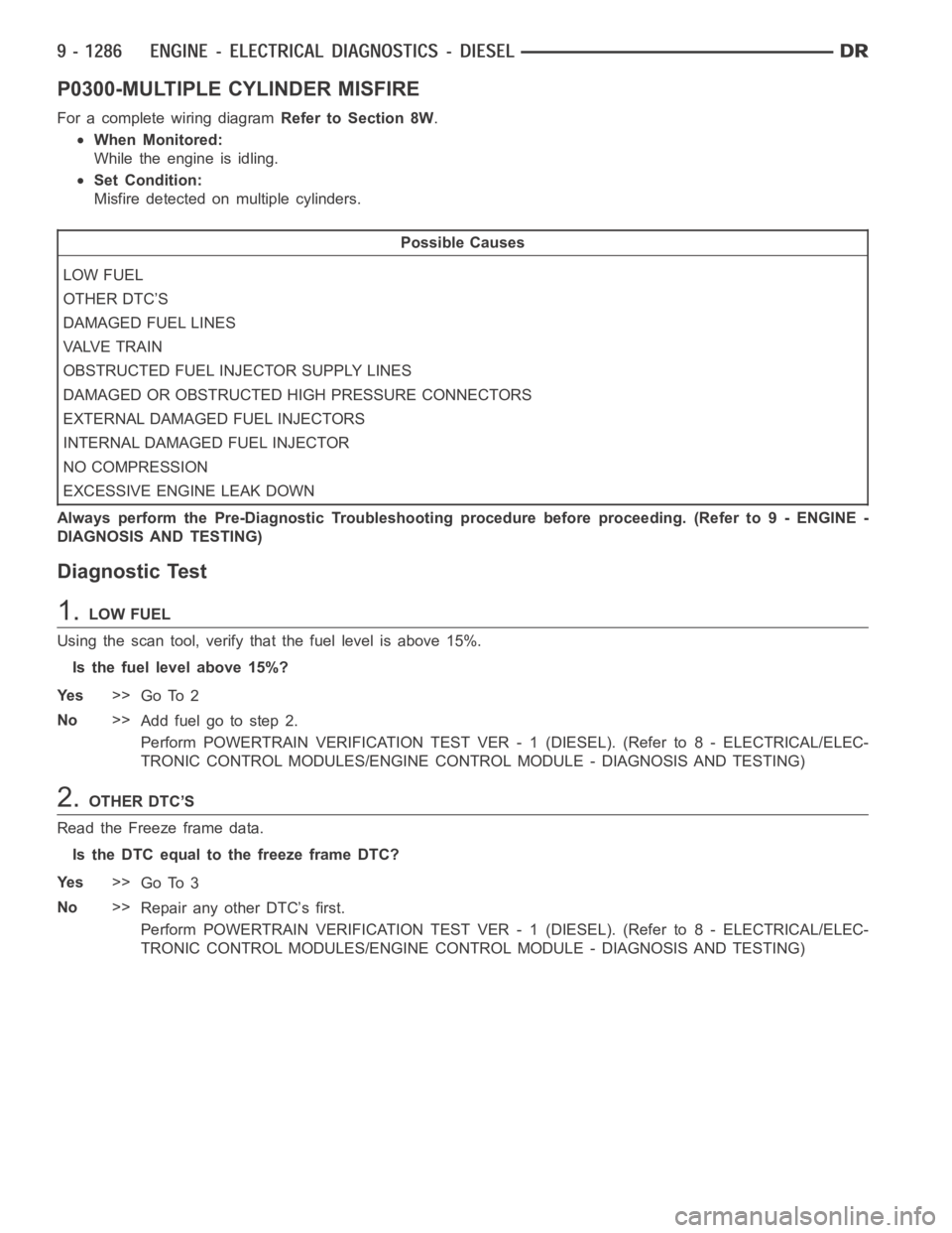
P0300-MULTIPLE CYLINDER MISFIRE
For a complete wiring diagramRefer to Section 8W.
When Monitored:
While the engine is idling.
Set Condition:
Misfire detected on multiple cylinders.
Possible Causes
LOW FUEL
OTHER DTC’S
DAMAGED FUEL LINES
VA LV E T R A I N
OBSTRUCTED FUEL INJECTOR SUPPLY LINES
DAMAGED OR OBSTRUCTED HIGH PRESSURE CONNECTORS
EXTERNAL DAMAGED FUEL INJECTORS
INTERNAL DAMAGED FUEL INJECTOR
NO COMPRESSION
EXCESSIVE ENGINE LEAK DOWN
Always perform the Pre-Diagnostic Troubleshooting procedure before proceeding. (Refer to 9 - ENGINE -
DIAGNOSIS AND TESTING)
Diagnostic Test
1.LOW FUEL
Using the scan tool, verify that the fuel level is above 15%.
Is the fuel level above 15%?
Ye s>>
Go To 2
No>>
Addfuelgotostep2.
Perform POWERTRAIN VERIFICATION TEST VER - 1 (DIESEL). (Refer to 8 - ELECTRICAL/ELEC-
TRONIC CONTROL MODULES/ENGINE CONTROL MODULE - DIAGNOSIS AND TESTING)
2.OTHER DTC’S
Read the Freeze frame data.
Is the DTC equal to the freeze frame DTC?
Ye s>>
Go To 3
No>>
Repair any other DTC’s first.
Perform POWERTRAIN VERIFICATION TEST VER - 1 (DIESEL). (Refer to 8 - ELECTRICAL/ELEC-
TRONIC CONTROL MODULES/ENGINE CONTROL MODULE - DIAGNOSIS AND TESTING)
Page 596 of 5267
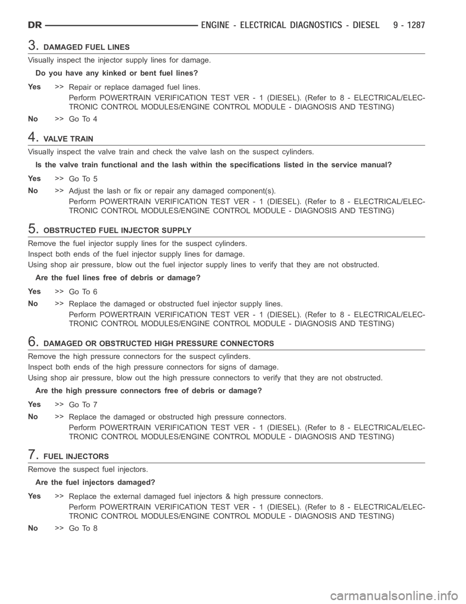
3.DAMAGED FUEL LINES
Visually inspect the injector supply lines for damage.
Do you have any kinked or bent fuel lines?
Ye s>>
Repair or replace damaged fuel lines.
Perform POWERTRAIN VERIFICATION TEST VER - 1 (DIESEL). (Refer to 8 - ELECTRICAL/ELEC-
TRONIC CONTROL MODULES/ENGINE CONTROL MODULE - DIAGNOSIS AND TESTING)
No>>
Go To 4
4.VA LV E T R A I N
Visually inspect the valve train and check the valve lash on the suspect cylinders.
Is the valve train functional and the lash within the specifications listed in the service manual?
Ye s>>
Go To 5
No>>
Adjust the lash or fix or repair any damaged component(s).
Perform POWERTRAIN VERIFICATION TEST VER - 1 (DIESEL). (Refer to 8 - ELECTRICAL/ELEC-
TRONIC CONTROL MODULES/ENGINE CONTROL MODULE - DIAGNOSIS AND TESTING)
5.OBSTRUCTED FUEL INJECTOR SUPPLY
Remove the fuel injector supply lines for the suspect cylinders.
Inspect both ends of the fuel injector supply lines for damage.
Using shop air pressure, blow out the fuel injector supply lines to verify that they are not obstructed.
Are the fuel lines free of debris or damage?
Ye s>>
Go To 6
No>>
Replace the damaged or obstructed fuel injector supply lines.
Perform POWERTRAIN VERIFICATION TEST VER - 1 (DIESEL). (Refer to 8 - ELECTRICAL/ELEC-
TRONIC CONTROL MODULES/ENGINE CONTROL MODULE - DIAGNOSIS AND TESTING)
6.DAMAGED OR OBSTRUCTED HIGH PRESSURE CONNECTORS
Remove the high pressure connectors for the suspect cylinders.
Inspect both ends of the high pressure connectors for signs of damage.
Using shop air pressure, blow out the high pressure connectors to verify that they are not obstructed.
Are the high pressure connectors free of debris or damage?
Ye s>>
Go To 7
No>>
Replace the damaged or obstructed high pressure connectors.
Perform POWERTRAIN VERIFICATION TEST VER - 1 (DIESEL). (Refer to 8 - ELECTRICAL/ELEC-
TRONIC CONTROL MODULES/ENGINE CONTROL MODULE - DIAGNOSIS AND TESTING)
7.FUEL INJECTORS
Remove the suspect fuel injectors.
Are the fuel injectors damaged?
Ye s>>
Replace the external damaged fuel injectors & high pressure connectors.
Perform POWERTRAIN VERIFICATION TEST VER - 1 (DIESEL). (Refer to 8 - ELECTRICAL/ELEC-
TRONIC CONTROL MODULES/ENGINE CONTROL MODULE - DIAGNOSIS AND TESTING)
No>>
Go To 8
Page 597 of 5267
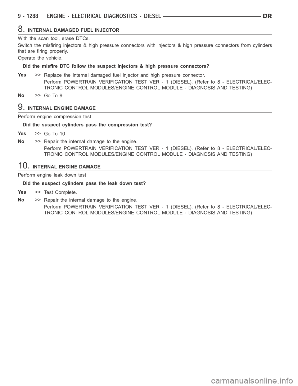
8.INTERNAL DAMAGED FUEL INJECTOR
With the scan tool, erase DTCs.
Switch the misfiring injectors & high pressure connectors with injectors& high pressure connectors from cylinders
that are firing properly.
Operate the vehicle.
Did the misfire DTC follow the suspect injectors & high pressure connectors?
Ye s>>
Replace the internal damaged fuel injector and high pressure connector.
Perform POWERTRAIN VERIFICATION TEST VER - 1 (DIESEL). (Refer to 8 - ELECTRICAL/ELEC-
TRONIC CONTROL MODULES/ENGINE CONTROL MODULE - DIAGNOSIS AND TESTING)
No>>
Go To 9
9.INTERNAL ENGINE DAMAGE
Perform engine compression test
Did the suspect cylinders pass the compression test?
Ye s>>
Go To 10
No>>
Repair the internal damage to the engine.
Perform POWERTRAIN VERIFICATION TEST VER - 1 (DIESEL). (Refer to 8 - ELECTRICAL/ELEC-
TRONIC CONTROL MODULES/ENGINE CONTROL MODULE - DIAGNOSIS AND TESTING)
10.INTERNAL ENGINE DAMAGE
Perform engine leak down test
Did the suspect cylinders pass the leak down test?
Ye s>>
Te s t C o m p l e t e .
No>>
Repair the internal damage to the engine.
Perform POWERTRAIN VERIFICATION TEST VER - 1 (DIESEL). (Refer to 8 - ELECTRICAL/ELEC-
TRONIC CONTROL MODULES/ENGINE CONTROL MODULE - DIAGNOSIS AND TESTING)
Page 598 of 5267
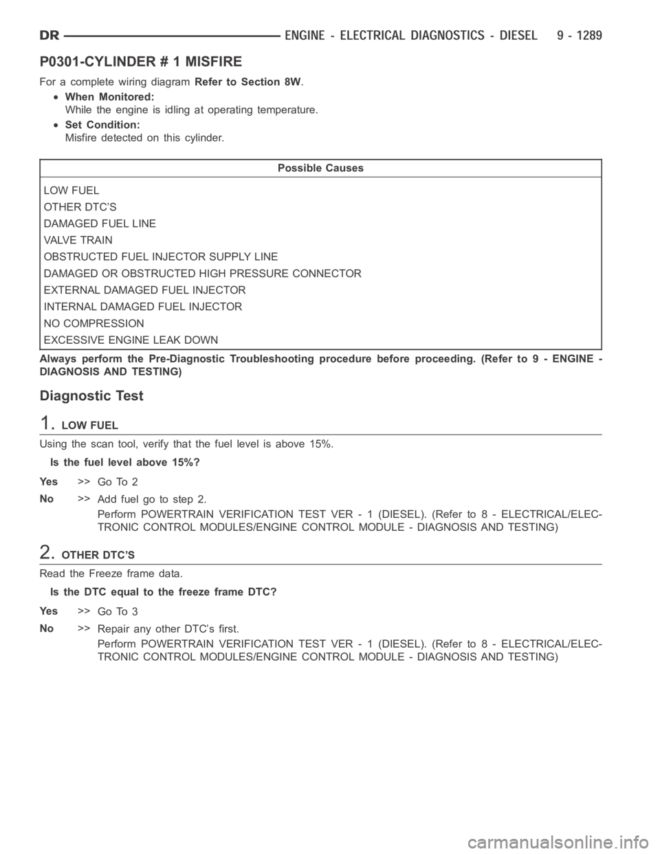
P0301-CYLINDER # 1 MISFIRE
For a complete wiring diagramRefer to Section 8W.
When Monitored:
While the engine is idling at operating temperature.
Set Condition:
Misfire detected on this cylinder.
Possible Causes
LOW FUEL
OTHER DTC’S
DAMAGED FUEL LINE
VA LV E T R A I N
OBSTRUCTED FUEL INJECTOR SUPPLY LINE
DAMAGED OR OBSTRUCTED HIGH PRESSURE CONNECTOR
EXTERNAL DAMAGED FUEL INJECTOR
INTERNAL DAMAGED FUEL INJECTOR
NO COMPRESSION
EXCESSIVE ENGINE LEAK DOWN
Always perform the Pre-Diagnostic Troubleshooting procedure before proceeding. (Refer to 9 - ENGINE -
DIAGNOSIS AND TESTING)
Diagnostic Test
1.LOW FUEL
Using the scan tool, verify that the fuel level is above 15%.
Is the fuel level above 15%?
Ye s>>
Go To 2
No>>
Addfuelgotostep2.
Perform POWERTRAIN VERIFICATION TEST VER - 1 (DIESEL). (Refer to 8 - ELECTRICAL/ELEC-
TRONIC CONTROL MODULES/ENGINE CONTROL MODULE - DIAGNOSIS AND TESTING)
2.OTHER DTC’S
Read the Freeze frame data.
Is the DTC equal to the freeze frame DTC?
Ye s>>
Go To 3
No>>
Repair any other DTC’s first.
Perform POWERTRAIN VERIFICATION TEST VER - 1 (DIESEL). (Refer to 8 - ELECTRICAL/ELEC-
TRONIC CONTROL MODULES/ENGINE CONTROL MODULE - DIAGNOSIS AND TESTING)
Page 599 of 5267
3.DAMAGED FUEL LINE
Visually inspect the injector supply line for damage.
Do you have any kinked or bent fuel lines?
Ye s>>
Repair or replace the damaged fuel line.
Perform POWERTRAIN VERIFICATION TEST VER - 1 (DIESEL). (Refer to 8 - ELECTRICAL/ELEC-
TRONIC CONTROL MODULES/ENGINE CONTROL MODULE - DIAGNOSIS AND TESTING)
No>>
Go To 4
4.VA LV E T R A I N
Visually inspect the valve train and check the valve lash on the suspect cylinder.
Is the valve train functional and the lash within the specifications listed in the service manual?
Ye s>>
Go To 5
No>>
Adjust the lash or fix or repair any damaged component(s).
Perform POWERTRAIN VERIFICATION TEST VER - 1 (DIESEL). (Refer to 8 - ELECTRICAL/ELEC-
TRONIC CONTROL MODULES/ENGINE CONTROL MODULE - DIAGNOSIS AND TESTING)
5.OBSTRUCTED FUEL INJECTOR SUPPLY
Remove the fuel injector supply line for the suspect cylinder.
Inspect both ends of the fuel injector supply line for damage.
Using shop air pressure, blow out the fuel injector supply line to verify that they are not obstructed.
Are the fuel lines free of debris or damage?
Ye s>>
Go To 6
No>>
Replace the damaged or obstructed fuel injector supply line.
Perform POWERTRAIN VERIFICATION TEST VER - 1 (DIESEL). (Refer to 8 - ELECTRICAL/ELEC-
TRONIC CONTROL MODULES/ENGINE CONTROL MODULE - DIAGNOSIS AND TESTING)
6.DAMAGED OR OBSTRUCTED HIGH PRESSURE CONNECTOR
Remove the high pressure connector for the suspect cylinder.
Inspect both ends of the high pressure connector for signs of damage.
Using shop air pressure, blow out the high pressure connector to verify that it is not obstructed.
Are the high pressure connectors free of debris or damage?
Ye s>>
Go To 7
No>>
Replace the damaged or obstructed high pressure connector.
Perform POWERTRAIN VERIFICATION TEST VER - 1 (DIESEL). (Refer to 8 - ELECTRICAL/ELEC-
TRONIC CONTROL MODULES/ENGINE CONTROL MODULE - DIAGNOSIS AND TESTING)
7.FUEL INJECTOR
Remove the suspect fuel injector.
Are the fuel injectors damaged?
Ye s>>
Replace the external damaged fuel injector & high pressure connector.
Perform POWERTRAIN VERIFICATION TEST VER - 1 (DIESEL). (Refer to 8 - ELECTRICAL/ELEC-
TRONIC CONTROL MODULES/ENGINE CONTROL MODULE - DIAGNOSIS AND TESTING)
No>>
Go To 8
Page 600 of 5267
8.INTERNAL DAMAGED FUEL INJECTOR
With the scan tool, erase DTCs.
Switch the misfiring injector & high pressure connector with an injector &high pressure connector from a cylinder
that is firing properly.
Operate the vehicle.
Did the misfire DTC follow the suspect injectors & high pressure connectors?
Ye s>>
Replace the internal damaged fuel injector and high pressure connector.
Perform POWERTRAIN VERIFICATION TEST VER - 1 (DIESEL). (Refer to 8 - ELECTRICAL/ELEC-
TRONIC CONTROL MODULES/ENGINE CONTROL MODULE - DIAGNOSIS AND TESTING)
No>>
Go To 9
9.INTERNAL ENGINE DAMAGE
Perform engine compression test
Did the suspect cylinders pass the compression test?
Ye s>>
Go To 10
No>>
Repair the internal damage to the engine.
Perform POWERTRAIN VERIFICATION TEST VER - 1 (DIESEL). (Refer to 8 - ELECTRICAL/ELEC-
TRONIC CONTROL MODULES/ENGINE CONTROL MODULE - DIAGNOSIS AND TESTING)
10.INTERNAL ENGINE DAMAGE
Perform engine leak down test
Did the suspect cylinders pass the leak down test?
Ye s>>
Te s t C o m p l e t e .
No>>
Repair the internal damage to the engine.
Perform POWERTRAIN VERIFICATION TEST VER - 1 (DIESEL). (Refer to 8 - ELECTRICAL/ELEC-
TRONIC CONTROL MODULES/ENGINE CONTROL MODULE - DIAGNOSIS AND TESTING)