tow DODGE RAM SRT-10 2006 Service Owner's Manual
[x] Cancel search | Manufacturer: DODGE, Model Year: 2006, Model line: RAM SRT-10, Model: DODGE RAM SRT-10 2006Pages: 5267, PDF Size: 68.7 MB
Page 1861 of 5267
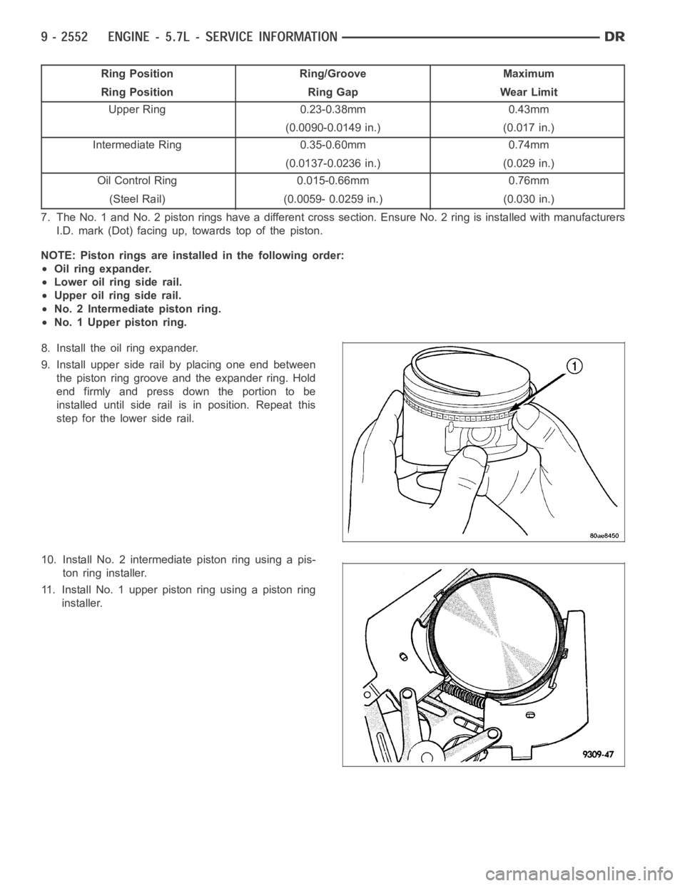
Ring Position Ring/Groove Maximum
Ring Position Ring Gap Wear Limit
Upper Ring 0.23-0.38mm 0.43mm
(0.0090-0.0149 in.) (0.017 in.)
Intermediate Ring 0.35-0.60mm 0.74mm
(0.0137-0.0236 in.) (0.029 in.)
Oil Control Ring 0.015-0.66mm 0.76mm
(Steel Rail) (0.0059- 0.0259 in.) (0.030 in.)
7. The No. 1 and No. 2 piston rings have a different cross section. Ensure No.2 ring is installed with manufacturers
I.D. mark (Dot) facing up, towards top of the piston.
NOTE: Piston rings are installed in the following order:
Oil ring expander.
Lower oil ring side rail.
Upper oil ring side rail.
No. 2 Intermediate piston ring.
No. 1 Upper piston ring.
8. Install the oil ring expander.
9. Install upper side rail by placing one end between
the piston ring groove and the expander ring. Hold
end firmly and press down the portion to be
installed until side rail is in position. Repeat this
step for the lower side rail.
10. Install No. 2 intermediate piston ring using a pis-
ton ring installer.
11. Install No. 1 upper piston ring using a piston ring
installer.
Page 1888 of 5267
INSPECTION
1. Inspect the intake sealing surface for cracks, nicks and distortion.
2. Inspect the intake manifold vacuum hose fittings for looseness or blockage.
3. Inspect the manifold to throttlebody mating surface for cracks, nicks and distortion.
INSTALLATION
1. Install intake manifold seals.
2. Position intake manifold and IAFM.
3. Install intake manifold retaining bolts, and tighten in sequence from the middle bolts towards the outside in a
crisscross pattern. Torque fasteners to 12 Nꞏm (105 in. lbs.).
4. Connect electrical connectors for the following components:
Manifold Absolute Pressure (MAP) Sensor
Intake Air Temperature (IAT) Sensor
Throttle Position (TPS) Sensor
Coolant Temperature (CTS) Sensor
Idle Air Control (IAC) Motor
5. Install generator.
6. Install A/C compressor.
7. Connect Brake booster hose and Positive crankcase ventilation (PCV) hose.
8. Install resonator assembly and air inlet hose.
9. Connect negative cable to battery.
Page 1911 of 5267
EXCESSIVE BLUE SMOKE
POSSIBLE CAUSE CORRECTION
Restricted turbocharger drain tube. Remove turbocharger drain tube and remove
obstruction.
Crankcase ventilation system plugged. Inspect crankcase ventilation system for function
Valve seals are worn, brittle, or improperly installed. Replace valve stemoilseals(Referto9-ENGINE/
CYLINDER HEAD/INTAKE/EXHAUST VALVES &
SEATS - REMOVAL).
Valve stems and/or guides are worn. Remove valves and inspect valves and guides. (Refer
to 9 - ENGINE/CYLINDER HEAD/INTAKE/EXHAUST
VALVES & SEATS - STANDARD PROCEDURE).
Broken or Improperly installed piston rings. Tear down engine and inspectpiston rings.
Excessive piston ring end gap. Remove pistons and measure piston ring end gap
(Refer to 9 - ENGINE/ENGINE BLOCK/PISTON RINGS
- STANDARD PROCEDURE).
Excessive cylinder bore wear and taper. Remove pistons and measure cylinder bore wear and
taper (Refer to 9 - ENGINE/ENGINE BLOCK -
STANDARD PROCEDURE).
Cylinder damage. Remove pistons and inspect cylinder bore for cracks or
porosity. Repair with cylinder liner if necessary. (Refer
to 9 - ENGINE/ENGINE BLOCK - STANDARD
PROCEDURE).
Piston damage. Remove pistons and inspect for cracks, holes. Measure
piston for out-of-round and taper (Refer to 9 -
ENGINE/ENGINE BLOCK/PISTON & CONNECTING
ROD - INSPECTION).
Turbocharger failure. (Refer to 11 - EXHAUST SYSTEM/TURBOCHARGER
SYSTEM/TURBOCHARGER - INSPECTION).
DIAGNOSIS AND TESTING - CYLINDER COMPRESSION/LEAKAGE TESTS
CYLINDER COMPRESSION PRESSURE
The results of a cylinder compressionpressure test can be utilized to diagnose several engine malfunctions.
Ensure batteries are completely charged and the engine starter motor is ingood operating condition. Otherwise, the
indicated compression pressures may not be valid for diagnostic purposes.
1. Disconnect the fuel inlet line to the fuel filter housing. Plug the fuel line from the fuel tank.
NOTE: Failure to plug fuel line will result in fuel leak.
2. Remove fuel transfer pump relay from PDC.
3. Start the engine and idle until the engine stalls (runs out of fuel).
4. Remove the cylinder head cover. (Refer to 9 - ENGINE/CYLINDER HEAD/CYLINDER HEAD COVER(S) -
REMOVAL)
5. Remove the cylinder head cover carrier gasket. (Refer to 9 - ENGINE/CYLINDER HEAD/CYLINDER HEAD
COVER(S) - REMOVAL)
6. Remove the high pressure fuel line between the cylinder head and fuel rail for the cylinder to be tested. Use
tool# 9011 to cap this fuel rail on the cylinder being tested.
7. Remove the fuel connector tube nut and fuel connector tube.
8. Remove the exhaust rocker lever.
9. Use Tool 9010 to remove the injector and copper sealing washer.
10. Install the exhaust rocker lever and torque to 36 Nꞏm (27 ft. lbs.).
11. Cover the remaining rocker levers with clean shop towels to prevent anyoil splatter under the hood.
Page 1913 of 5267
MoparEngine RTV GEN II is used to seal components exposed to engine oil. This material is a specially designed
black silicone rubber RTV that retains adhesion and sealing properties when exposed to engine oil. Moisture in the
air causes the material to cure. This material is available in three ounce tubes and has a shelf life of one year. After
one year this material will not properly cure. Always inspect the package for the expiration date before use.
MOPAR
AT F R T V
Mopar
ATF RTV is a specifically designed black silicone rubber RTV that retains adhesion and sealing properties
to seal components exposed to automatic transmission fluid, engine coolants, and moisture. This material is avail-
able in three ounce tubes and has a shelf life of one year. After one year thismaterial will not properly cure. Always
inspect the package for the expiration date before use.
MOPAR
GASKET MAKER
Mopar
Gasket Maker is an anaerobic type gasket material. The material cures in the absence of air when
squeezed between two metallic surfaces. It will not cure if left in the uncovered tube. The anaerobic material is for
use between two machined surfaces. Do not use on flexible metal flanges.
MOPAR
GASKET SEALANT
Mopar
Gasket Sealant is a slow drying, permanently soft sealer. This material isrecommended for sealing
threaded fittings and gaskets against leakage of oil and coolant. Can be used on threaded and machined parts
under all temperatures. This material is used on engines with multi-layersteel (MLS) cylinder head gaskets. This
material also will prevent corrosion. Mopar
Gasket Sealant is available in a 13 oz. aerosol can or 4oz./16 oz. can
w/applicator.
FORM-IN-PLACE GASKET AND SEALER APPLICATION
Assembling parts using a form-in-place gasket requires care but it’s easier than using precut gaskets.
Mopar
Gasket Maker material should be applied sparingly 1 mm (0.040 in.) diameter or less of sealant to one
gasket surface. Be certain the material surrounds each mounting hole. Excess material can easily be wiped off.
Components should be torqued in place within 15 minutes. The use of a locating dowel is recommended during
assembly to prevent smearing material off the location.
Mopar
Engine RTV GEN II or ATF RTV gasket material should be applied in a continuous bead approximately 3
mm (0.120 in.) in diameter. All mounting holes must be circled. For corner sealing, a 3.17 or 6.35 mm (1/8 or 1/4 in.)
drop is placed in the center of the gasket contact area. Uncured sealant maybe removed with a shop towel. Com-
ponents should be torqued in place while the sealant is still wet to the touch (within 10 minutes). The usage of a
locating dowel is recommended during assembly to prevent smearing material off the location.
Mopar
Gasket Sealant in an aerosol can should be applied using a thin, even coat sprayed completely over both
surfaces to be joined, and both sides of a gasket. Then proceed with assembly. Material in a can w/applicator can
be brushed on evenly over the sealing surfaces. Material in an aerosol can shouldbeusedonengineswithmulti-
layer steel gaskets.
STANDARD PROCEDURE - REPAIR DAMAGED OR WORN THREADS
CAUTION: Be sure that the tapped holes maintain the original center line.
Damaged or worn threads can be repaired. Essentially, this repair consistsof:
Drilling out worn or damaged threads.
Tapping the hole with a special Heli-Coil Tap, or equivalent.
Installing an insert into the tapped hole to bring the hole back to its original thread size.
STANDARD PROCEDURE—HYDROSTATIC LOCK
CAUTION: DO NOT use the starter motor to rotate the crankshaft. Severe damage could occur.
When an engine is suspected of hydrostatic lock (regardless of what causedthe problem), follow the steps below.
1. Disconnect the negative cable(s) from the battery.
2. Inspect air cleaner, induction system, and intake manifold to ensure system is dry and clear of foreign material.
Page 1914 of 5267
3. Place a shop towel around the fuel injectors to catch any fluid that may possibly be under pressure in the cyl-
inder head. Remove the fuel injectors (Refer to 14 - FUEL SYSTEM/FUEL INJECTION/FUEL INJECTOR -
REMOVAL).
4. With all injectors removed, rotatethe crankshaft using the crankshaftbarring tool (PN 7471–B).
5. Identify the fluid in the cylinders (coolant, fuel, oil, etc.).
6. Be sure all fluid has been removed from the cylinders.
7. Repair engine or components as necessary to prevent this problem from occurring again.
8. Squirt a small amount of engine oil into the cylinders to lubricate the walls. This will prevent damage on restart.
9. Install fuel injectors (Refer to 14 - FUEL SYSTEM/FUEL INJECTION/FUEL INJECTOR - INSTALLATION).
10. Drain engine oil. Remove and discard the oil filter (Refer to 9 - ENGINE/LUBRICATION/OIL FILTER -
REMOVAL).
11. Installthedrainplug.Tightentheplugto50Nꞏm(37ft.lbs.)torque.
12. Install a new oil filter (Refer to 9 - ENGINE/LUBRICATION/OIL FILTER - INSTALLATION).
13. Fill engine crankcase with the specified amount and grade of oil (Referto LUBRICATION & MAINTENANCE/
FLUID TYPES - SPECIFICATIONS).
14. Connect the negative cable(s) to the battery.
15. Start the engine and check for any leaks.
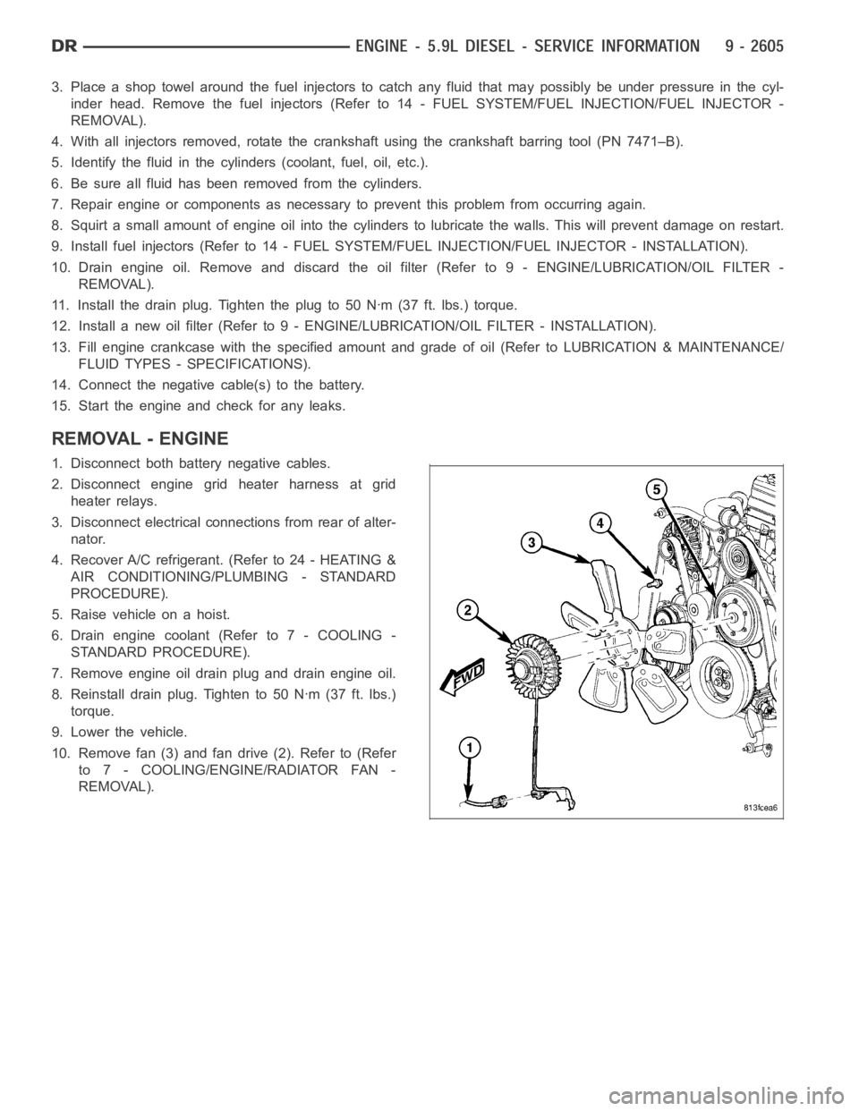
REMOVAL - ENGINE
1. Disconnect both battery negative cables.
2. Disconnect engine grid heater harness at grid
heater relays.
3. Disconnect electrical connections from rear of alter-
nator.
4. Recover A/C refrigerant. (Refer to 24 - HEATING &
AIR CONDITIONING/PLUMBING - STANDARD
PROCEDURE).
5. Raise vehicle on a hoist.
6. Drain engine coolant (Refer to 7 - COOLING -
STANDARD PROCEDURE).
7. Remove engine oil drain plug and drain engine oil.
8. Reinstall drain plug. Tighten to 50 Nꞏm (37 ft. lbs.)
torque.
9. Lower the vehicle.
10. Remove fan (3) and fan drive (2). Refer to (Refer
to 7 - COOLING/ENGINE/RADIATOR FAN -
REMOVAL).
Page 1961 of 5267
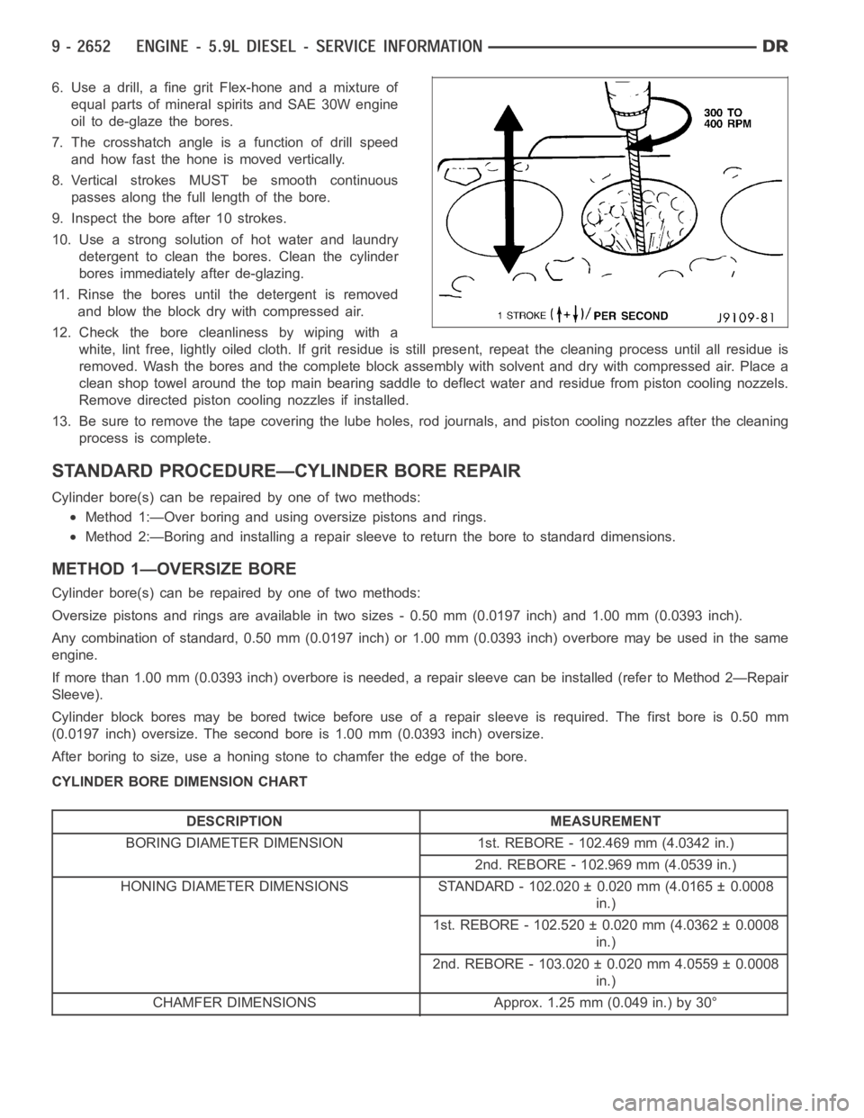
6. Use a drill, a fine grit Flex-hone and a mixture of
equal parts of mineral spirits and SAE 30W engine
oil to de-glaze the bores.
7. The crosshatch angle is a function of drill speed
and how fast the hone is moved vertically.
8. Vertical strokes MUST be smooth continuous
passes along the full length of the bore.
9. Inspect the bore after 10 strokes.
10. Use a strong solution of hot water and laundry
detergent to clean the bores. Clean the cylinder
bores immediately after de-glazing.
11. Rinse the bores until the detergent is removed
and blow the block dry with compressed air.
12. Check the bore cleanliness by wiping with a
white, lint free, lightly oiled cloth. If grit residue is still present, repeat the cleaning process until all residue is
removed. Wash the bores and the complete block assembly with solvent and dry with compressed air. Place a
clean shop towel around the top main bearing saddle to deflect water and residue from piston cooling nozzels.
Remove directed piston cooling nozzles if installed.
13. Be sure to remove the tape covering the lube holes, rod journals, and piston cooling nozzles after the cleaning
process is complete.
STANDARD PROCEDURE—CYLINDER BORE REPAIR
Cylinder bore(s) can be repaired by one of two methods:
Method 1:—Over boring and using oversize pistons and rings.
Method 2:—Boring and installing a repair sleeve to return the bore to standard dimensions.
METHOD 1—OVERSIZE BORE
Cylinder bore(s) can be repaired by one of two methods:
Oversize pistons and rings are available in two sizes - 0.50 mm (0.0197 inch) and 1.00 mm (0.0393 inch).
Any combination of standard, 0.50 mm (0.0197 inch) or 1.00 mm (0.0393 inch)overbore may be used in the same
engine.
If more than 1.00 mm (0.0393 inch) overbore is needed, a repair sleeve can beinstalled (refer to Method 2—Repair
Sleeve).
Cylinder block bores may be bored twice before use of a repair sleeve is required. The first bore is 0.50 mm
(0.0197 inch) oversize. The second bore is 1.00 mm (0.0393 inch) oversize.
After boring to size, use a honing stone to chamfer the edge of the bore.
CYLINDER BORE DIMENSION CHART
DESCRIPTION MEASUREMENT
BORING DIAMETER DIMENSION 1st. REBORE - 102.469 mm (4.0342 in.)
2nd. REBORE - 102.969 mm (4.0539 in.)
HONING DIAMETER DIMENSIONS STANDARD - 102.020 ± 0.020 mm (4.0165 ± 0.0008
in.)
1st. REBORE - 102.520 ± 0.020 mm (4.0362 ± 0.0008
in.)
2nd. REBORE - 103.020 ± 0.020 mm 4.0559 ± 0.0008
in.)
CHAMFER DIMENSIONS Approx. 1.25 mm (0.049 in.) by 30°
Page 1979 of 5267
SEAL - CRANKSHAFT OIL - REAR
REMOVAL
1. Disconnect the battery negative cables.
2. Remove the transmission and transfer case (if
equipped).
3. Remove the clutch cover and disc (if manual trans-
mission equipped) (Refer to 6 - CLUTCH/CLUTCH
DISC - REMOVAL).
4. Remove the flywheel or converter drive plate.
5. Remove the flywheel adapter plate.
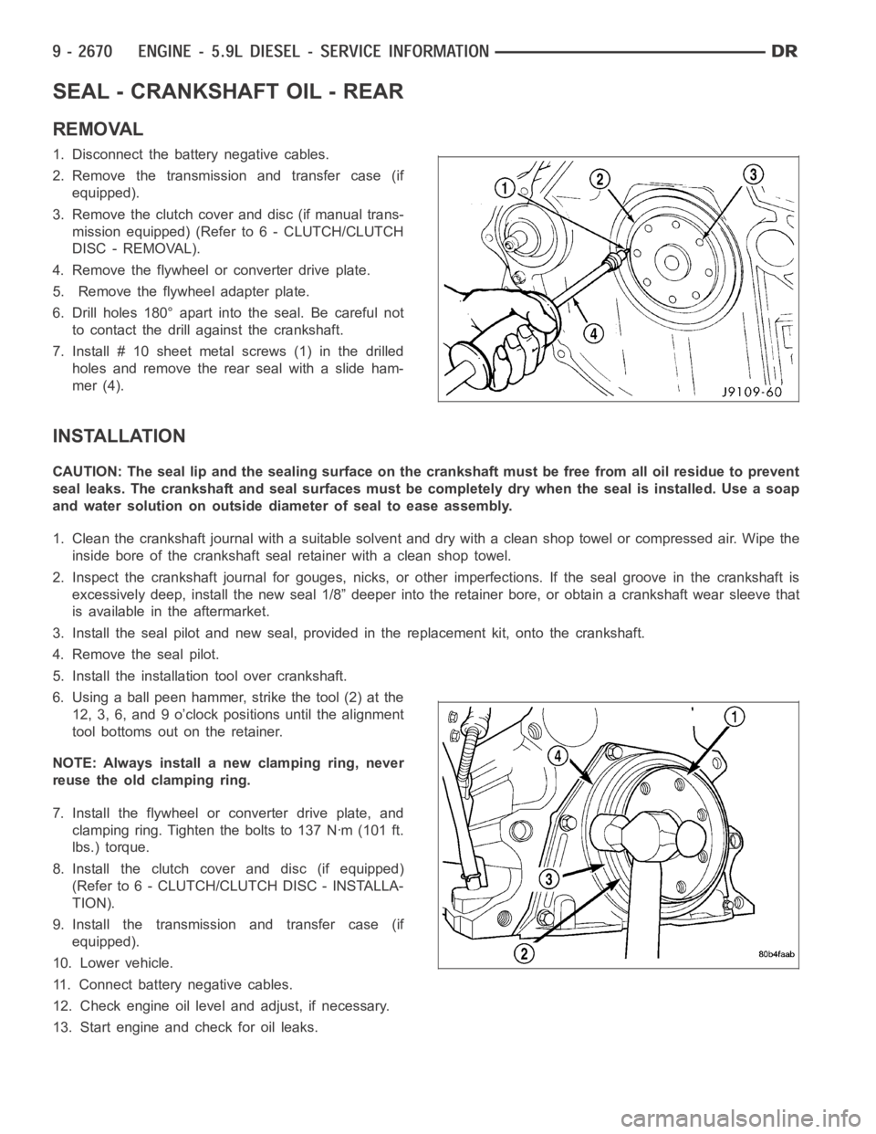
6. Drill holes 180° apart into the seal. Be careful not
to contact the drill against the crankshaft.
7. Install # 10 sheet metalscrews (1) in the drilled
holes and remove the rear seal with a slide ham-
mer (4).
INSTALLATION
CAUTION: The seal lip and the sealing surface on the crankshaft must be freefrom all oil residue to prevent
seal leaks. The crankshaft and seal surfaces must be completely dry when the seal is installed. Use a soap
and water solution on outside diameter of seal to ease assembly.
1. Clean the crankshaft journal with a suitable solvent and dry with a cleanshop towel or compressed air. Wipe the
inside bore of the crankshaft seal retainer with a clean shop towel.
2. Inspect the crankshaft journal forgouges, nicks, or other imperfections. If the seal groove in the crankshaft is
excessively deep, install the new seal 1/8” deeper into the retainer bore,or obtain a crankshaft wear sleeve that
is available in the aftermarket.
3. Install the seal pilot and new seal, provided in the replacement kit, onto the crankshaft.
4. Remove the seal pilot.
5. Install the installation tool over crankshaft.
6. Using a ball peen hammer, strike the tool (2) at the
12, 3, 6, and 9 o’clock positions until the alignment
tool bottoms out on the retainer.
NOTE: Always install a new clamping ring, never
reuse the old clamping ring.
7. Install the flywheel or converter drive plate, and
clamping ring. Tighten the bolts to 137 Nꞏm (101 ft.
lbs.) torque.
8. Install the clutch cover and disc (if equipped)
(Refer to 6 - CLUTCH/CLUTCH DISC - INSTALLA-
TION).
9. Install the transmission and transfer case (if
equipped).
10. Lower vehicle.
11. Connect battery negative cables.
12. Check engine oil level and adjust, if necessary.
13. Start engine and check for oil leaks.
Page 1982 of 5267
TAPPETS - VALVE
REMOVAL
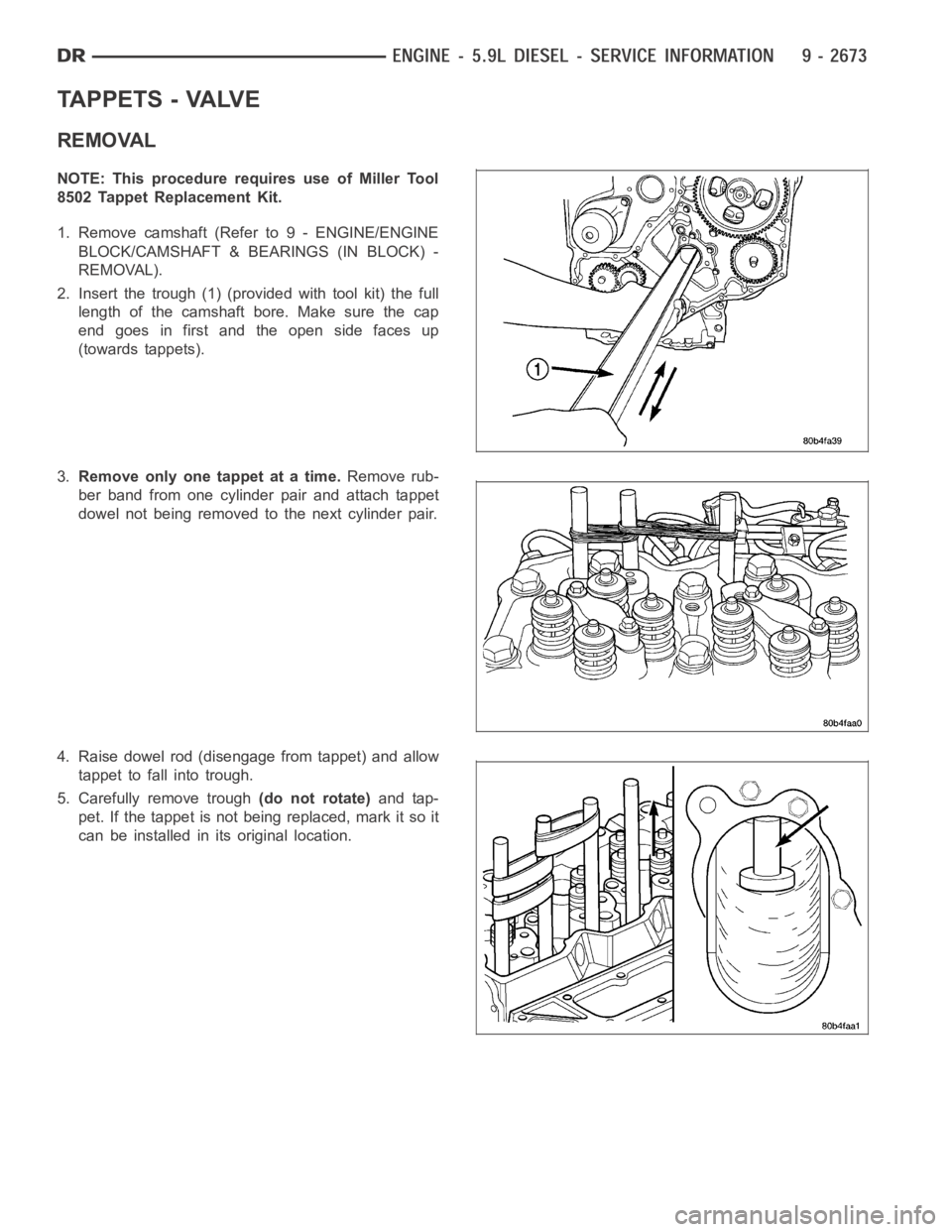
NOTE: This procedure requires use of Miller Tool
8502 Tappet Replacement Kit.
1. Remove camshaft (Refer to 9 - ENGINE/ENGINE
BLOCK/CAMSHAFT & BEARINGS (IN BLOCK) -
REMOVAL).
2. Insert the trough (1) (provided with tool kit) the full
length of the camshaft bore. Make sure the cap
end goes in first and the open side faces up
(towards tappets).
3.Remove only one tappet at a time.Remove rub-
ber band from one cylinder pair and attach tappet
dowel not being removed to the next cylinder pair.
4. Raise dowel rod (disengage from tappet) and allow
tappet to fall into trough.
5. Carefully remove trough(do not rotate)and tap-
pet. If the tappet is not being replaced, mark it so it
can be installed in its original location.
Page 1983 of 5267
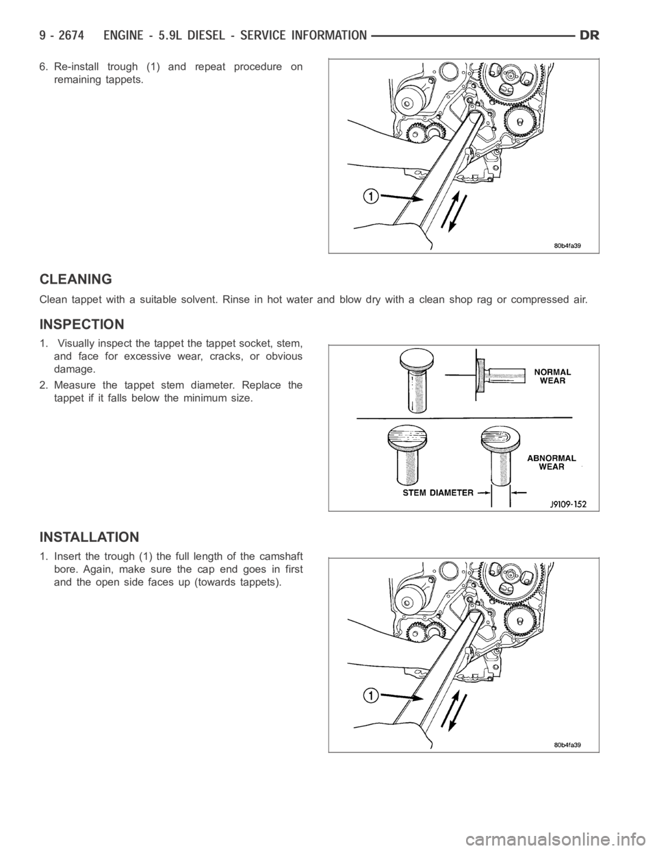
6. Re-install trough (1) and repeat procedure on
remaining tappets.
CLEANING
Clean tappet with a suitable solvent. Rinse in hot water and blow dry with a clean shop rag or compressed air.
INSPECTION
1. Visually inspect the tappet the tappet socket, stem,
and face for excessive wear, cracks, or obvious
damage.
2. Measure the tappet stem diameter. Replace the
tappet if it falls below the minimum size.
INSTALLATION
1. Insert the trough (1) the full length of the camshaft
bore. Again, make sure the cap end goes in first
and the open side faces up (towards tappets).
Page 1985 of 5267
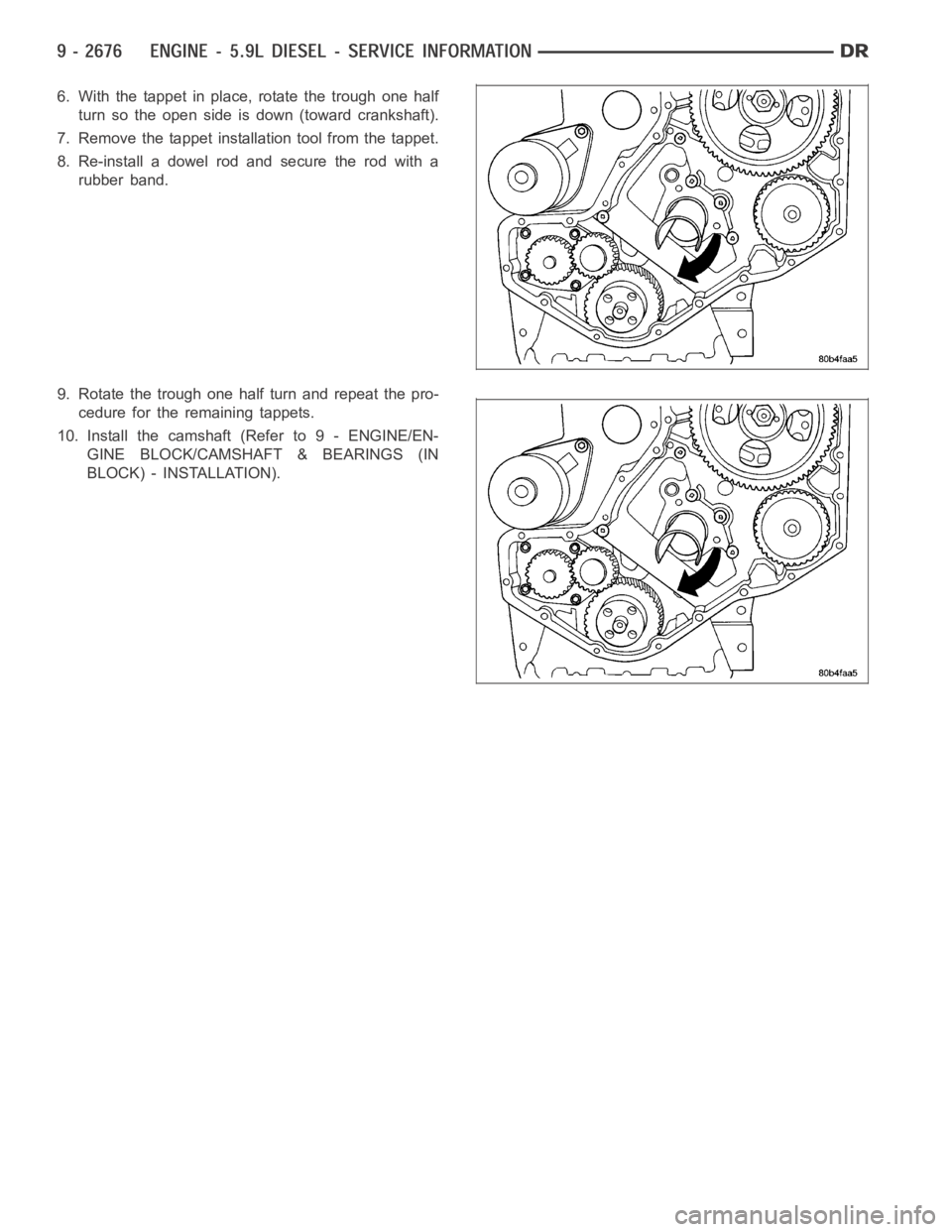
6. With the tappet in place, rotate the trough one half
turn so the open side is down (toward crankshaft).
7. Remove the tappet installation tool from the tappet.
8. Re-install a dowel rod and secure the rod with a
rubber band.
9. Rotate the trough one half turn and repeat the pro-
cedure for the remaining tappets.
10. Install the camshaft (Refer to 9 - ENGINE/EN-
GINE BLOCK/CAMSHAFT & BEARINGS (IN
BLOCK) - INSTALLATION).