DODGE RAM SRT-10 2006 Service Repair Manual
RAM SRT-10 2006
DODGE
DODGE
https://www.carmanualsonline.info/img/12/56917/w960_56917-0.png
DODGE RAM SRT-10 2006 Service Repair Manual
Trending: height, engine, spark plugs, fuel pump, lumbar support, air suspension, Crankshaft
Page 3001 of 5267
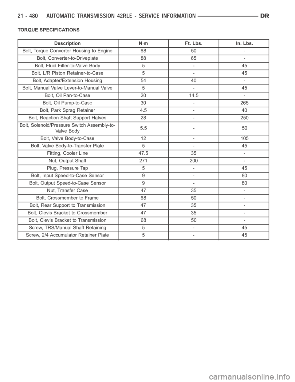
TORQUE SPECIFICATIONS
Description Nꞏm Ft. Lbs. In. Lbs.
Bolt, Torque Converter Housing to Engine 68 50 -
Bolt, Converter-to-Driveplate 88 65 -
Bolt, Fluid Filter-to-Valve Body 5 - 45
Bolt, L/R Piston Retainer-to-Case 5 - 45
Bolt, Adapter/Extension Housing 54 40 -
Bolt, Manual Valve Lever-to-Manual Valve 5 - 45
Bolt, Oil Pan-to-Case 20 14.5 -
Bolt, Oil Pump-to-Case 30 - 265
Bolt, Park Sprag Retainer 4.5 - 40
Bolt, Reaction Shaft Support Halves 28 - 250
Bolt, Solenoid/Pressure Switch Assembly-to-
Valve Body5.5 - 50
Bolt, Valve Body-to-Case 12 - 105
Bolt, Valve Body-to-Transfer Plate 5 - 45
Fitting, Cooler Line 47.5 35 -
Nut, Output Shaft 271 200 -
Plug, Pressure Tap 5 - 45
Bolt, Input Speed-to-Case Sensor 9 - 80
Bolt, Output Speed-to-Case Sensor 9 - 80
Nut, Transfer Case 47 35 -
Bolt, Crossmember to Frame 68 50 -
Bolt, Rear Support to Transmission 47 35 -
Bolt, Clevis Bracket to Crossmember 47 35 -
Bolt, Clevis Bracket to Transmission 68 50 -
Screw, TRS/Manual Shaft Retaining 5 - 45
Screw, 2/4 Accumulator Retainer Plate 5 - 45
Page 3002 of 5267
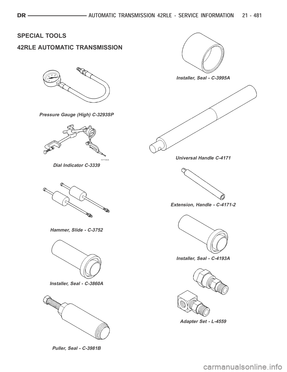
SPECIAL TOOLS
42RLE AUTOMATIC TRANSMISSION
Pressure Gauge (High) C-3293SP
Dial Indicator C-3339
Hammer, Slide - C-3752
Installer, Seal - C-3860A
Puller, Seal - C-3981B
Installer, Seal - C-3995A
Universal Handle C-4171
Extension, Handle - C-4171-2
Installer, Seal - C-4193A
Adapter Set - L-4559
Page 3003 of 5267
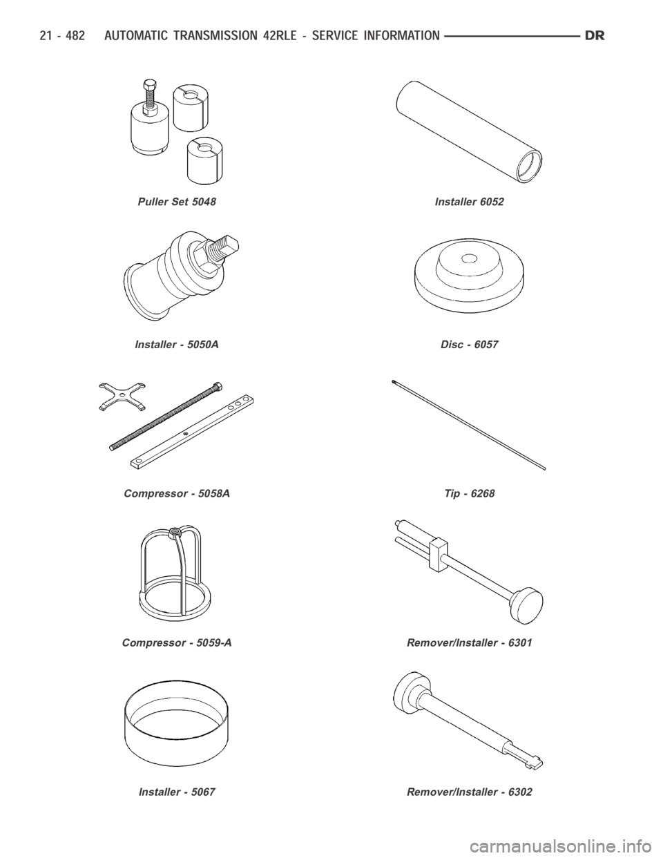
Puller Set 5048
Installer - 5050A
Compressor - 5058A
Compressor - 5059-A
Installer - 5067
Installer 6052
Disc - 6057
Tip - 6268
Remover/Installer - 6301
Remover/Installer - 6302
Page 3004 of 5267
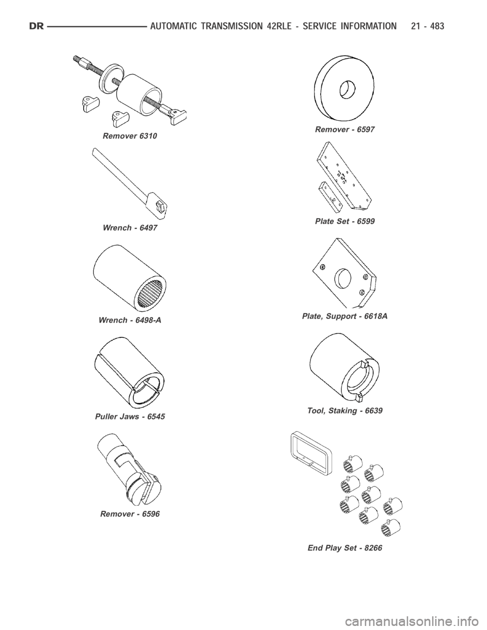
Remover 6310
Wrench - 6497
Wrench - 6498-A
Puller Jaws - 6545
Remover - 6596
Remover - 6597
Plate Set - 6599
Plate, Support - 6618A
Tool, Staking - 6639
End Play Set - 8266
Page 3005 of 5267
Page 3006 of 5267
ACCUMULATOR
DESCRIPTION
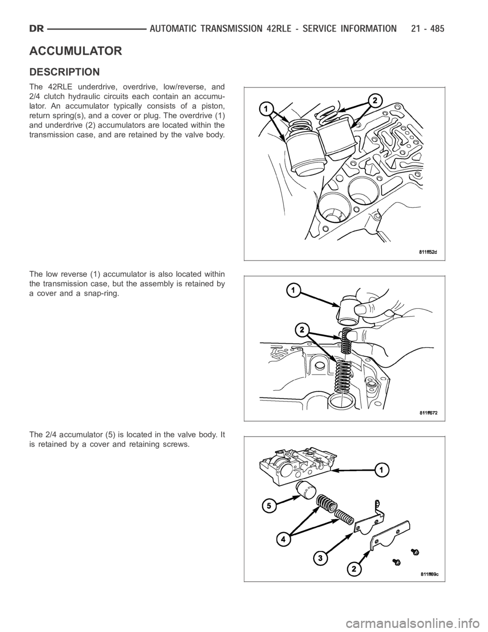
The 42RLE underdrive, overdrive, low/reverse, and
2/4 clutch hydraulic circuits each contain an accumu-
lator. An accumulator typically consists of a piston,
return spring(s), and a cover or plug. The overdrive (1)
and underdrive (2) accumulators are located within the
transmission case, and are retained by the valve body.
The low reverse (1) accumulator is also located within
the transmission case, but the assembly is retained by
a cover and a snap-ring.
The 2/4 accumulator (5) is located in the valve body. It
is retained by a cover and retaining screws.
Page 3007 of 5267
OPERATION
The function of an accumulator is to cushion the application of a frictional clutch element. When pressurized fluid is
applied to a clutch circuit, the application force is dampened by fluid collecting in the respective accumulator cham-
ber against the piston and springs. The intended result is a smooth, firm clutch application.
Page 3008 of 5267
SEAL-ADAPTER HOUSING
REMOVAL
1. Remove the transfer case (Refer to 21 - TRANSMISSION/TRANSFER CASE - REMOVAL).
2. Using a screw mounted in a slide hammer, remove the adapter housing seal.
INSTALLATION
1. Install a new adapter housing seal with Universal Handle C-4171 and SealInstaller C-3860-A.
2. Install the transfer case (Refer to 21 - TRANSMISSION/TRANSFER CASE - INSTALLATION).
Page 3009 of 5267
BEARINGS
ADJUSTMENTS
BEARING ADJUSTMENT PROCEDURES
Take extreme care when removing andinstalling bearing cups and cones.Use only an arbor press for installa-
tion,as a hammer may not properly align the bearing cup or cone. Burrs or nicks on the bearing seat will give a
false end play reading, while gauging for proper shims. Improperly seatedbearing cup and cones are subject to
low-mileage failure.
Bearing cups and cones should be replaced if they show signs of pitting or heat distress.
If distress is seen on either the cup or bearing rollers, both cup and cone must be replaced.
NOTE: Bearing drag torque specifications must be maintained to avoid premature bearing failures.
Used (original) bearing may lose up to 50 percent of the original drag torque after break-in.
NOTE: All bearing adjustments must be made with no other component interference or gear inter-mesh.
Oil all bearings before checking turning torque.
Page 3010 of 5267
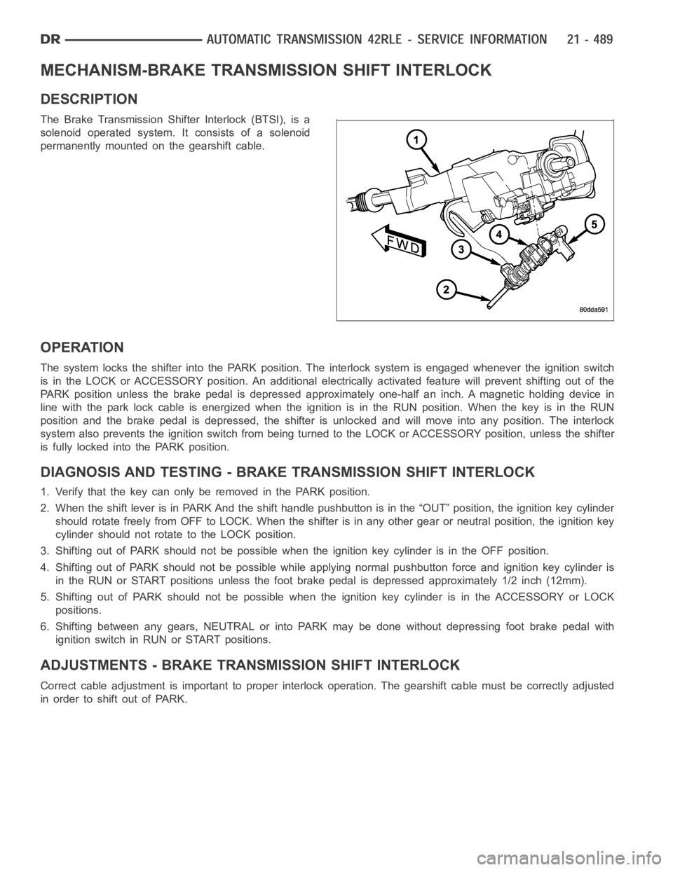
MECHANISM-BRAKE TRANSMISSION SHIFT INTERLOCK
DESCRIPTION
The Brake Transmission Shifter Interlock (BTSI), is a
solenoid operated system. It consists of a solenoid
permanently mounted on the gearshift cable.
OPERATION
The system locks the shifter into the PARK position. The interlock system is engaged whenever the ignition switch
is in the LOCK or ACCESSORY position. An additional electrically activated feature will prevent shifting out of the
PARK position unless the brake pedal is depressed approximately one-halfan inch. A magnetic holding device in
line with the park lock cable is energized when the ignition is in the RUN position. When the key is in the RUN
position and the brake pedal is depressed, the shifter is unlocked and willmove into any position. The interlock
system also prevents the ignition switch from being turned to the LOCK or ACCESSORY position, unless the shifter
is fully locked into the PARK position.
DIAGNOSIS AND TESTING - BRAKE TRANSMISSION SHIFT INTERLOCK
1. Verify that the key can only be removed in the PARK position.
2. When the shift lever is in PARK And the shift handle pushbutton is in the “OUT” position, the ignition key cylinder
should rotate freely from OFF to LOCK. When the shifter is in any other gear or neutral position, the ignition key
cylinder should not rotate to the LOCK position.
3. Shifting out of PARK should not be possible when the ignition key cylinder is in the OFF position.
4. Shifting out of PARK should not be possible while applying normal pushbutton force and ignition key cylinder is
in the RUN or START positions unless the foot brake pedal is depressed approximately 1/2 inch (12mm).
5. Shifting out of PARK should not be possible when the ignition key cylinderisintheACCESSORYorLOCK
positions.
6. Shifting between any gears, NEUTRAL or into PARK may be done without depressing foot brake pedal with
ignition switch in RUN or START positions.
ADJUSTMENTS - BRAKE TRANSMISSION SHIFT INTERLOCK
Correct cable adjustment is important to proper interlock operation. Thegearshift cable must be correctly adjusted
in order to shift out of PARK.
Trending: odometer, coolant capacity, brake sensor, brake, run flat, remote start, wheelbase

