oil type DODGE RAM SRT-10 2006 Service Owner's Guide
[x] Cancel search | Manufacturer: DODGE, Model Year: 2006, Model line: RAM SRT-10, Model: DODGE RAM SRT-10 2006Pages: 5267, PDF Size: 68.7 MB
Page 1989 of 5267
INSPECTION - CONNECTING ROD
Inspect the connecting rod for damage and wear. The
I-Beam section of the connecting rod cannot have
dents or other damage. Damage to this part can
cause stress risers which will progress to breakage.
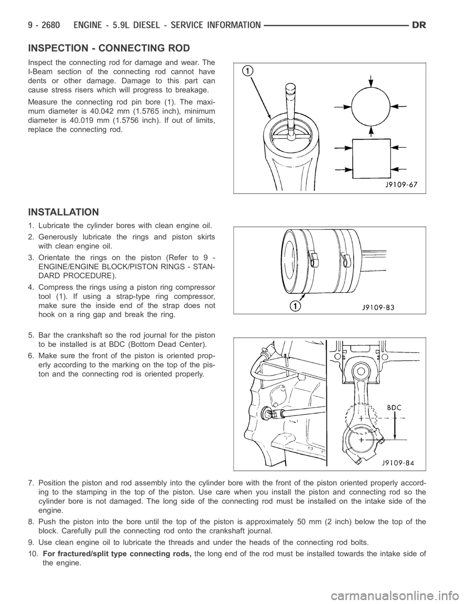
Measure the connecting rod pin bore (1). The maxi-
mum diameter is 40.042 mm (1.5765 inch), minimum
diameter is 40.019 mm (1.5756 inch). If out of limits,
replace the connecting rod.
INSTALLATION
1. Lubricate the cylinder bores with clean engine oil.
2. Generously lubricate the rings and piston skirts
with clean engine oil.
3. Orientate the rings on the piston (Refer to 9 -
ENGINE/ENGINE BLOCK/PISTON RINGS - STAN-
DARD PROCEDURE).
4. Compress the rings using a piston ring compressor
tool(1).Ifusingastrap-typeringcompressor,
make sure the inside end of the strap does not
hook on a ring gap and break the ring.
5. Bar the crankshaft so the rod journal for the piston
to be installed is at BDC(Bottom Dead Center).
6. Make sure the front of the piston is oriented prop-
erly according to the marking on the top of the pis-
ton and the connecting rod is oriented properly.
7. Position the piston and rod assemblyinto the cylinder bore with the front of the piston oriented properly accord-
ing to the stamping in the top of the piston. Use care when you install the piston and connecting rod so the
cylinder bore is not damaged. The long side of the connecting rod must be installed on the intake side of the
engine.
8. Push the piston into the bore until the top of the piston is approximately50 mm (2 inch) below the top of the
block. Carefully pull the connecting rod onto the crankshaft journal.
9. Use clean engine oil to lubricate the threads and under the heads of the connecting rod bolts.
10.For fractured/split type connecting rods,thelongendoftherodmustbeinstalledtowardstheintakesideof
the engine.
Page 1997 of 5267
LUBRICATION
DESCRIPTION
A gear driven gerotor type oil pump is mounted behind the front gear cover inthe lower right portion on the engine.
OPERATION
A gerotor style oil pump draws oil from the crankcase through the suction tube and delivers it through the block
where it enters the oil cooler cover and pressure regulator valve. When oilpressure exceeds 517 kPa (75 PSI), the
valve opens exposing the dump port, which routes excess oil back to the oil pump.
At the same time, oil is directed to a cast in passage in the oil cooler cover,leading to the oil cooler element. As the
oil travels through the element plates, it is cooled by engine coolant traveling past the outside of the plates. It is
then routed to the oil filter head and through a full flow oil filter. If a plugged filter is encountered, the filter by-pass
valve opens, allowing unfiltered oil to lubricate the engine. This condition can be avoided by frequent oil and filter
changes, per the maintenance schedules found in the owners manual. The by-pass valve is calibrated to open when
it sees a pressure drop of more than 345 kPa (50 psi) across the oil filter.
The oil filter head then divides the oil between the engine and the turbocharger. The turbocharger receives filtered,
cooled and pressurized oil through a supply line from the filter head. The oil lubricates the turbocharger and returns
to the pan by way of a drain tube connecting the bottom of the turbocharger toa tube in the cylinder block.
Page 2002 of 5267
OIL
STANDARD PROCEDURE
STANDARD PROCEDURE - ENGINE OIL LEVEL
CAUTION: Do not overfill crankcase with engine
oil, oil foaming and oil pressure loss can result.
To ensure proper lubrication of an engine, the engine
oil must be maintained at an acceptable level. The
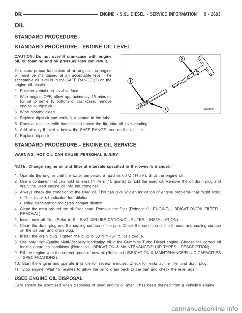
acceptable oil level is in the SAFE RANGE (3) on the
engine oil dipstick.
1. Position vehicle on level surface.
2. With engine OFF, allow approximately 15 minutes
for oil to settle to bottom of crankcase, remove
engine oil dipstick.
3. Wipe dipstick clean.
4. Replace dipstick and verify it is seated in the tube.
5. Remove dipstick, with handle held above the tip, take oil level reading.
6. Add oil only if level is below the SAFE RANGE area on the dipstick.
7. Replace dipstick.
STANDARD PROCEDURE - ENGINE OIL SERVICE
WARNING: HOT OIL CAN CAUSE PERSONAL INJURY.
NOTE: Change engine oil and filter at intervals specified in the owner’s manual.
1. Operate the engine until the water temperature reaches 60°C (140°F). Shut the engine off.
2. Use a container that can hold at least 14 liters (15 quarts) to hold the used oil. Remove the oil drain plug and
drain the used engine oil into the container.
3. Always check the condition of the used oil. This can give you an indication of engine problems that might exist.
Thin, black oil indicates fuel dilution.
Milky discoloration indicates coolant dilution.
4. Clean the area around the oil filter head. Remove the filter (Refer to 9 - ENGINE/LUBRICATION/OIL FILTER -
REMOVAL).
5. Install new oil filter (Refer to 9 - ENGINE/LUBRICATION/OIL FILTER - INSTA L L AT I O N ) .
6. Clean the drain plug and the sealing surface of the pan. Check the condition of the threads and sealing surface
on the oil pan and drain plug.
7. Install the drain plug. Tighten the plug to 50 Nꞏm (37 ft. lbs.) torque.
8. Use only High-Quality Multi-Viscosity lubricating oil in the Cummins Turbo Diesel engine. Choose the correct oil
for the operating conditions (Refer to LUBRICATION & MAINTENANCE/FLUID TYPES - DESCRIPTION).
9. Fill the engine with the correct grade of new oil (Refer to LUBRICATION & MAINTENANCE/FLUID CAPACITIES
- SPECIFICATIONS).
10. Start the engine and operate it at idle for several minutes. Check for leaks at the filter and drain plug.
11. Stop engine. Wait 15 minutes to allow the oil to drain back to the pan and check the level again.
USED ENGINE OIL DISPOSAL
Care should be exercised when disposing of used engine oil after it has beendrained from a vehicle’s engine.
Page 2004 of 5267
FILTER - ENGINE OIL
REMOVAL
1. Clean the area around the oil filter head. Remove the filter from below using a cap-style filter wrench.
2. Clean the gasket surface of the filter head. The filter canister O-Ring seal can stick on the filter head. Make sure
it is removed.
INSTALLATION
1. Fill the oil filter element with clean oil before installation. Use the same type oil that will be used in the engine.
2. Apply a light film of lubricating oil to the sealing surface before installing the filter.
CAUTION: Mechanical over-tightening may distort the threads or damage the filter element seal.
3. Install the filter until it contacts the sealing surface of the oil filter adapter. Tighten filter an additional
1⁄2turn.
Page 2031 of 5267
STANDARD PROCEDURE
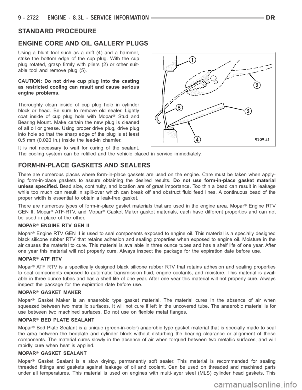
ENGINE CORE AND OIL GALLERY PLUGS
Using a blunt tool such as a drift (4) and a hammer,
strike the bottom edge of the cup plug. With the cup
plug rotated, grasp firmly with pliers (2) or other suit-
able tool and remove plug (5).
CAUTION: Do not drive cup plug into the casting
as restricted cooling can result and cause serious
engine problems.
Thoroughly clean inside of cup plug hole in cylinder
block or head. Be sure to remove old sealer. Lightly
coat inside of cup plug hole with Mopar
Stud and
Bearing Mount. Make certain the new plug is cleaned
of all oil or grease. Using proper drive plug, drive plug
into hole so that the sharp edge of the plug is at least
0.5 mm (0.020 in.) inside the lead-in chamfer.
It is not necessary to wait for curing of the sealant.
The cooling system can be refilled and the vehicle placed in service immediately.
FORM-IN-PLACE GASKETS AND SEALERS
There are numerous places where form-in-place gaskets are used on the engine. Care must be taken when apply-
ing form-in-place gaskets to assure obtaining the desired results.Do not use form-in-place gasket material
unless specified.Bead size, continuity, and location are of great importance. Too thin a bead can result in leakage
while too much can result in spill-overwhich can break off and obstruct fluid feed lines. A continuous bead of the
proper width is essential to obtain a leak-free gasket.
There are numerous types of form-in-place gasket materials that are used in the engine area. Mopar
Engine RTV
GEN II, Mopar
ATF-RTV, and MoparGasket Maker gasket materials, each have different properties and can not
be used in place of the other.
MOPAR
ENGINE RTV GEN II
Mopar
Engine RTV GEN II is used to seal components exposed to engine oil. This material is a specially designed
black silicone rubber RTV that retains adhesion and sealing properties when exposed to engine oil. Moisture in the
air causes the material to cure. This material is available in three ounce tubes and has a shelf life of one year. After
one year this material will not properly cure. Always inspect the package for the expiration date before use.
MOPAR
AT F R T V
Mopar
ATF RTV is a specifically designed black silicone rubber RTV that retains adhesion and sealing properties
to seal components exposed to automatic transmission fluid, engine coolants, and moisture. This material is avail-
able in three ounce tubes and has a shelf life of one year. After one year thismaterial will not properly cure. Always
inspect the package for the expiration date before use.
MOPAR
GASKET MAKER
Mopar
Gasket Maker is an anaerobic type gasket material. The material cures in the absence of air when
squeezed between two metallic surfaces. It will not cure if left in the uncovered tube. The anaerobic material is for
use between two machined surfaces. Do not use on flexible metal flanges.
MOPAR
BED PLATE SEALANT
Mopar
Bed Plate Sealant is a unique (green-in-color) anaerobic type gasket material that is specially made to seal
the area between the bedplate and cylinder block without disturbing the bearing clearance or alignment of these
components. The material cures slowly in the absence of air when torqued between two metallic surfaces, and will
rapidly cure when heat is applied.
MOPAR
GASKET SEALANT
Mopar
Gasket Sealant is a slow drying, permanently soft sealer. This material isrecommended for sealing
threaded fittings and gaskets against leakage of oil and coolant. Can be used on threaded and machined parts
under all temperatures. This material is used on engines with multi-layersteel (MLS) cylinder head gaskets. This
Page 2040 of 5267
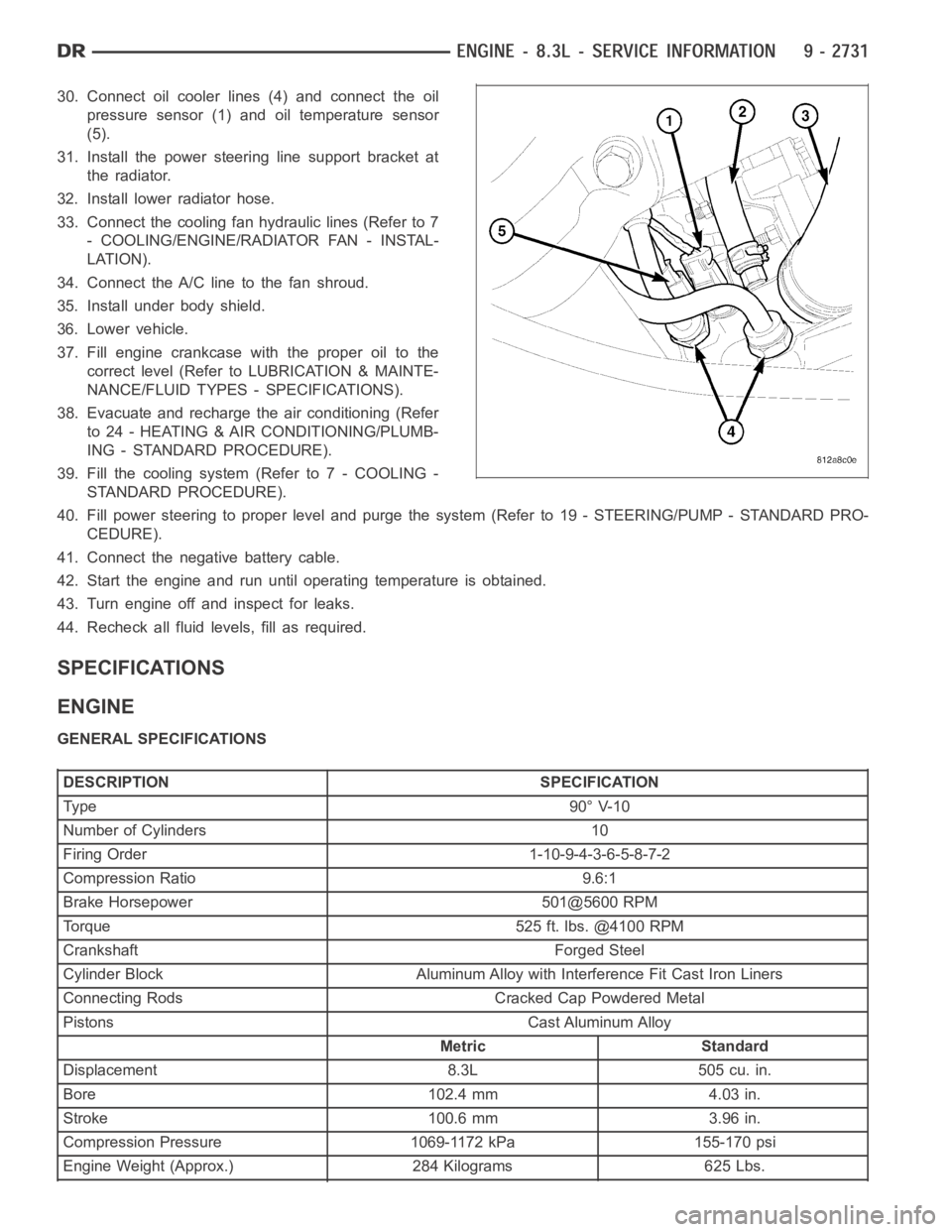
30. Connect oil cooler lines (4) and connect the oil
pressure sensor (1) and oil temperature sensor
(5).
31. Install the power steering line support bracket at
the radiator.
32. Install lower radiator hose.
33. Connect the cooling fan hydraulic lines (Refer to 7
- COOLING/ENGINE/RADIATOR FAN - INSTAL-
LATION).
34. Connect the A/C line to the fan shroud.
35. Install under body shield.
36. Lower vehicle.
37. Fill engine crankcase with the proper oil to the
correct level (Refer to LUBRICATION & MAINTE-
NANCE/FLUID TYPES - SPECIFICATIONS).
38. Evacuate and recharge the air conditioning (Refer
to 24 - HEATING & AIR CONDITIONING/PLUMB-
ING - STANDARD PROCEDURE).
39. Fill the cooling system (Refer to 7 - COOLING -
STANDARD PROCEDURE).
40. Fill power steering to proper leveland purge the system (Refer to 19 - STEERING/PUMP - STANDARD PRO-
CEDURE).
41. Connect the negative battery cable.
42. Start the engine and run until operating temperature is obtained.
43. Turn engine off and inspect for leaks.
44. Recheck all fluid levels, fill as required.
SPECIFICATIONS
ENGINE
GENERAL SPECIFICATIONS
DESCRIPTION SPECIFICATION
Ty pe 9 0° V-1 0
Number of Cylinders 10
Firing Order 1-10-9-4-3-6-5-8-7-2
Compression Ratio 9.6:1
Brake Horsepower 501@5600 RPM
Torque 525 ft. lbs. @4100 RPM
Crankshaft Forged Steel
Cylinder Block Aluminum Alloy with Interference Fit Cast Iron Liners
Connecting Rods Cracked Cap Powdered Metal
Pistons Cast Aluminum Alloy
Metric Standard
Displacement 8.3L 505 cu. in.
Bore 102.4 mm 4.03 in.
Stroke 100.6 mm 3.96 in.
Compression Pressure 1069-1172 kPa 155-170 psi
Engine Weight (Approx.) 284 Kilograms 625 Lbs.
Page 2068 of 5267
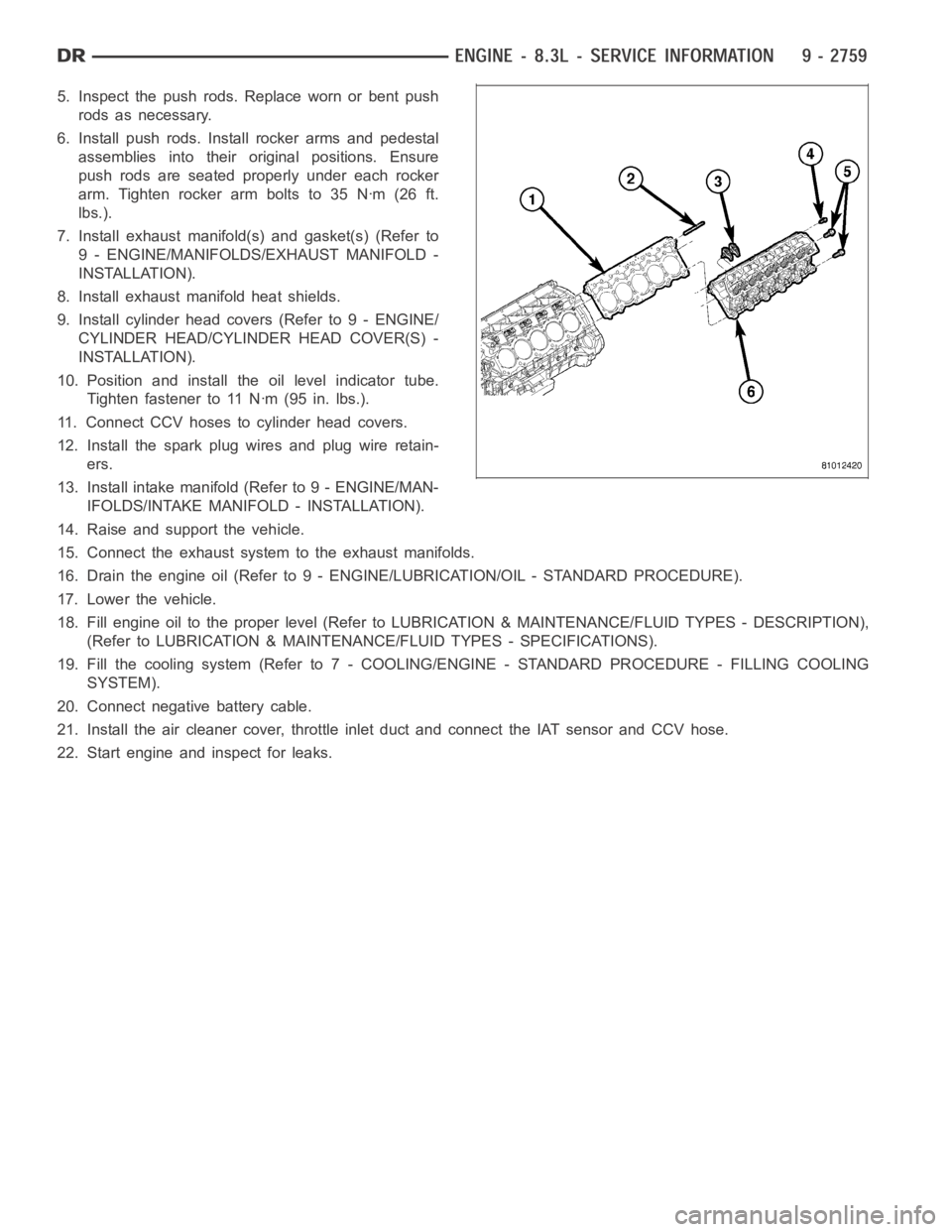
5. Inspect the push rods. Replace worn or bent push
rods as necessary.
6. Install push rods. Install rocker arms and pedestal
assemblies into their original positions. Ensure
push rods are seated properly under each rocker
arm.Tightenrockerarmboltsto35Nꞏm(26ft.
lbs.).
7. Install exhaust manifold(s) and gasket(s) (Refer to
9 - ENGINE/MANIFOLDS/EXHAUST MANIFOLD -
INSTALLATION).
8. Install exhaust manifold heat shields.
9. Install cylinder head covers (Refer to 9 - ENGINE/
CYLINDER HEAD/CYLINDER HEAD COVER(S) -
INSTALLATION).
10. Position and install the oil level indicator tube.
Tighten fastener to 11 Nꞏm (95 in. lbs.).
11. Connect CCV hoses to cylinder head covers.
12. Install the spark plug wires and plug wire retain-
ers.
13. Install intake manifold (Refer to 9 - ENGINE/MAN-
IFOLDS/INTAKE MANIFOLD - INSTALLATION).
14. Raise and support the vehicle.
15. Connect the exhaust systemto the exhaust manifolds.
16. Drain the engine oil (Refer to 9 - ENGINE/LUBRICATION/OIL - STANDARD PROCEDURE).
17. Lower the vehicle.
18. Fill engine oil to the proper level (Refer to LUBRICATION & MAINTENANCE/FLUID TYPES - DESCRIPTION),
(Refer to LUBRICATION & MAINTENANCE/FLUID TYPES - SPECIFICATIONS).
19. Fill the cooling system (Refer to 7 - COOLING/ENGINE - STANDARD PROCEDURE - FILLING COOLING
SYSTEM).
20. Connect negative battery cable.
21. Install the air cleaner cover, throttle inlet duct and connect the IAT sensor and CCV hose.
22. Start engine and inspect for leaks.
Page 2086 of 5267
LUBRICATION
DESCRIPTION
The engine lubrication system is a full-flow filtration pressure feed type.
OPERATION
Engine oil stored in the oil pan is taken in and discharged by an internal geartypeoilpump,whichisdrivenbythe
crankshaft. A pressure relief valve is located in the timing chain case cover; it regulates oil pressure. The oil is
pumped through an oil filter and feeds a main oil gallery. Also, oil is routedtoanexternaloilcooler.Themainoil
gallery feeds oil under pressure to the main bearings, connecting rod bearings, and camshaft bearings. Passages in
the cylinder block feed oil to the hydraulic lifters. The oil then flows through hollow pushrods, which feed the rocker
arm pivots.
DIAGNOSIS AND TESTING
CHECKING ENGINE OIL PRESSURE
1. Remove oil pressure sensor (Refer to 9 - ENGINE/LUBRICATION/OIL PRESSURE SENSOR - REMOVAL).
2. Install oil pressure gauge.
3. Warm engine at high idle until thermostat opens.
CAUTION: If oil pressure is 0 at idle, Do Not Run engine at 3000 RPM.
4. Oil pressure should be 68.9 kPa (10 psi) at idle or 310 - 517 kPa (45 - 75 psi)at 3000 RPM.
5. If oil pressure is 0 at idle, shut off engine. Check for a clogged oil pick-up screen or a pressure relief valve stuck
open.
ENGINE OIL LEAK
Begin with a thorough visual inspection of the engine, particularly at thearea of the suspected leak. If an oil leak
source is not readily identifiable, thefollowingstepsshouldbefollowed:
1. Do not clean or degrease the engine at this time because some solvents maycause rubber to swell, temporarily
stopping the leak.
2. Add an oil soluble dye (use as recommended by manufacturer). Start the engine and let idle for approximately 15
minutes. Check the oil dipstick to make sure the dye is thoroughly mixed as indicated with a bright yellow color
under a black light.
3. Using a black light, inspect the entire engine for fluorescent dye, particularly at the suspected area of oil leak. If
the oil leak is found and identified, repair per service manual instructions.
4. If dye is not observed, drive the vehicle at various speeds for approximately 24 km (15 miles), and repeat inspec-
tion.If the oil leak source is not positively identified at this time, proceed with the air leak detection test
method.
Air Leak Detection Test Method
1. Remove the PCV valve from the IAFM. Cap or plug the PCV valve grommet.
2. Attach an air hose with pressure gauge and regulator to the dipstick tube.
CAUTION: Do not subject the engine assembly to more than 20.6 kPa (3 PSI) of test pressure.
3. Gradually apply air pressure from 6.89 - 17.23 kPa (1 - 2.5 psi) maximum while applying soapy water at the
suspected source. Adjust the regulator to the suitable test pressure thatprovide the best bubbles which will pin-
point the leak source. If the oil leak is detected and identified, repair per service manual procedures.
4. If the leakage occurs at the rear oil seal area, refer to the section, Inspection for Rear Seal Area Leak.
5. If no leaks are detected, turn off the air supply and remove the air hose and all plugs and caps. Install the PCV
valve.
6. Clean the oil off the suspect oil leak area using a suitable solvent. Drive the vehicle at various speeds approx-
imately 24 km (15 miles). Inspect the engine for signs of an oil leak by usinga black light.
Page 2088 of 5267
OIL
STANDARD PROCEDURE
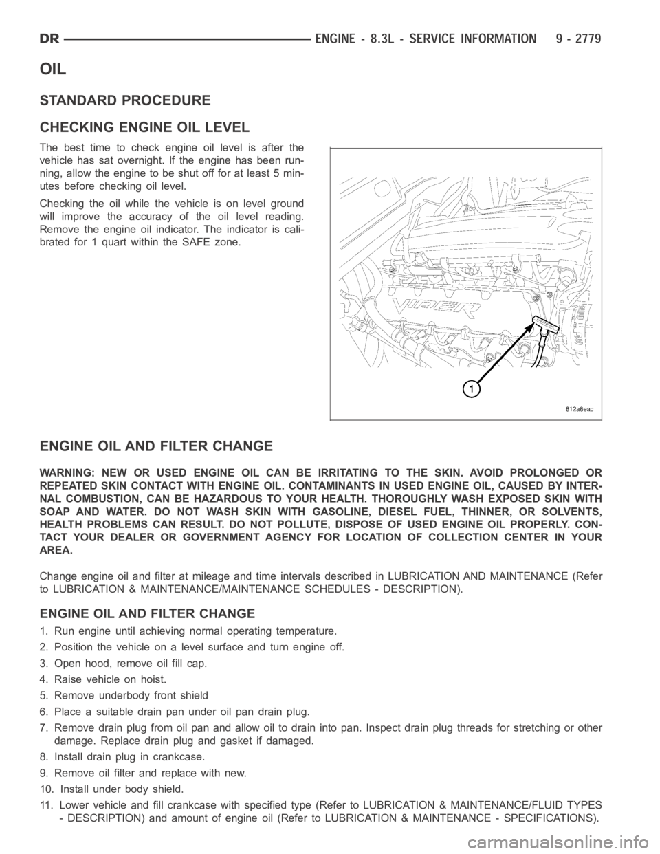
CHECKING ENGINE OIL LEVEL
The best time to check engine oil level is after the
vehicle has sat overnight. If the engine has been run-
ning, allow the engine to be shut off for at least 5 min-
utes before checking oil level.
Checking the oil while the vehicle is on level ground
will improve the accuracy of the oil level reading.
Remove the engine oil indicator. The indicator is cali-
brated for 1 quart within the SAFE zone.
ENGINE OIL AND FILTER CHANGE
WARNING: NEW OR USED ENGINE OIL CAN BE IRRITATING TO THE SKIN. AVOID PROLONGED OR
REPEATED SKIN CONTACT WITH ENGINE OIL. CONTAMINANTS IN USED ENGINE OIL, CAUSED BY INTER-
NAL COMBUSTION, CAN BE HAZARDOUS TO YOUR HEALTH. THOROUGHLY WASH EXPOSED SKIN WITH
SOAP AND WATER. DO NOT WASH SKIN WITH GASOLINE, DIESEL FUEL, THINNER, OR SOLVENTS,
HEALTH PROBLEMS CAN RESULT. DO NOT POLLUTE, DISPOSE OF USED ENGINE OIL PROPERLY. CON-
TACT YOUR DEALER OR GOVERNMENT AGENCY FOR LOCATION OF COLLECTION CENTER INYOUR
AREA.
Change engine oil and filter at mileage and time intervals described in LUBRICATION AND MAINTENANCE (Refer
to LUBRICATION & MAINTENANCE/MAINTENANCE SCHEDULES - DESCRIPTION).
ENGINE OIL AND FILTER CHANGE
1. Run engine until achieving normal operating temperature.
2. Position the vehicle on a level surface and turn engine off.
3. Open hood, remove oil fill cap.
4. Raise vehicle on hoist.
5. Remove underbody front shield
6. Place a suitable drain pan under oil pan drain plug.
7. Remove drain plug from oil pan and allow oil to drain into pan. Inspect drain plug threads for stretching or other
damage. Replace drain plug and gasket if damaged.
8. Install drain plug in crankcase.
9. Remove oil filter and replace with new.
10. Install under body shield.
11. Lower vehicle and fill crankcase with specified type (Refer to LUBRICATION & MAINTENANCE/FLUID TYPES
- DESCRIPTION) and amount of engine oil (Refer to LUBRICATION & MAINTENANCE - SPECIFICATIONS).
Page 2089 of 5267
12. Install oil fill cap.
13. Start engine and inspect for leaks.
14. Stop engine and inspect oil level. Adjust oil level as necessary.
OIL SPECIFICATION
DaimlerChrysler Corporation recommends a fully synthetic API certifiedengine oil of the proper viscosity grade for
refill. Viper engine factory fill is Mobil 1
10W-30 Synthetic.
OIL FILTER SPECIFICATION
All DaimlerChrysler Corporation engines are equipped with a high qualityfull-flow, disposable type oil filter.
DaimlerChrysler Corporation recommends a Mopar
or equivalent oil filter be used.
USED ENGINE OIL DISPOSAL
Care should be exercised when disposing used engine oil after it has been drained from a vehicle engine.