DODGE RAM SRT-10 2006 Service Repair Manual
Manufacturer: DODGE, Model Year: 2006, Model line: RAM SRT-10, Model: DODGE RAM SRT-10 2006Pages: 5267, PDF Size: 68.7 MB
Page 4031 of 5267
7.INSTRUMENT CLUSTER
Repair
Replace the Instrument Cluster in accordance with the Service Information.
Perform the BODY VERIFICATION TEST-VER 1 (Refer to 8 - ELECTRICAL/ELECTRONIC CONTROL
MODULES - STANDARD PROCEDURE) and TRANSFER CASE VERIFICATION TEST-VER 1 (Refer to
21 - TRANSMISSION/TRANSAXLE/TRANSFER CASE - STANDARD PROCEDURE).
8.INTERMITTENT WIRING AND CONNECTORS
The conditions necessary to set this DTC are not present at this time.
Using the wiring diagram/schematic as a guide, inspect the wiring and connectors.
While monitoring the scan tool data relative to this circuit, wiggle test the wiring and connectors.
Look for the data to change or for the DTC to reset during the wiggle test.
Were any problems found?
Ye s>>
Repair as necessary.
Perform the TRANSFER CASE VERIFICATION TEST-VER 1. (Refer to 21 - TRANSMISSION/TRANS-
AXLE/TRANSFER CASE - STANDARD PROCEDURE)
No>>
Te s t c o m p l e t e .
Page 4032 of 5267

C1404- TRANSFER CASE RANGE POSITION SENSOR CIRCUIT LOW
For a complete wiring diagramRefer to Section 8W
Page 4033 of 5267
When Monitored:
Ignition on. Battery voltage between 9.0 and 16.0 volts.
Set Condition:
The TIPM detects a short to ground on the Transfer Case Position Sensor Signal circuit for 2.0 seconds.
Possible Causes
(T103) 5 VOLT SUPPLY CIRCUIT OPEN
(T103) 5 VOLT SUPPLY CIRCUIT SHORTED TO GROUND
(D201) MODE SENSOR A CIRCUIT SHORTED TO GROUND
(D201) MODE SENSOR A CIRCUIT SHORTED TO (G180) SENSOR RETURN CIRCUIT
SHIFT MOTOR/MODE SENSOR ASSEMBLY
TOTALLY INTERGRATED POWER MODULE (TIPM)
Diagnostic Test
1.T-CASE POSITION SENSOR VOLTAGE BELOW 0.2 VOLTS
Ignition on, engine not running.
With the scan tool under TIPM, read the T-Case Position Sensor voltage.
Is the voltage below 0.2 volts?
Ye s>>
Go to 2
No>>
Go to 8
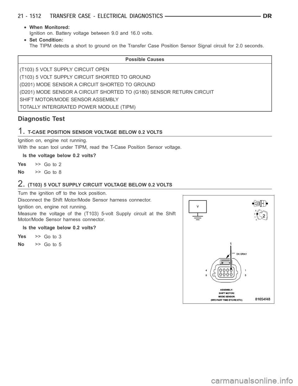
2.(T103) 5 VOLT SUPPLY CIRCUIT VOLTAGE BELOW 0.2 VOLTS
Turn the ignition off to the lock position.
Disconnect the Shift Motor/Mode Sensor harness connector.
Ignition on, engine not running.
Measure the voltage of the (T103) 5-volt Supply circuit at the Shift
Motor/Mode Sensor harness connector.
Is the voltage below 0.2 volts?
Ye s>>
Go to 3
No>>
Go to 5
Page 4034 of 5267
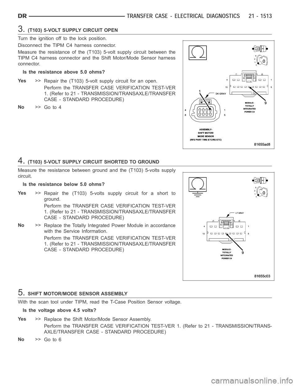
3.(T103) 5-VOLT SUPPLY CIRCUIT OPEN
Turn the ignition off to the lock position.
Disconnect the TIPM C4 harness connector.
Measure the resistance of the (T103) 5-volt supply circuit between the
TIPM C4 harness connector and the Shift Motor/Mode Sensor harness
connector.
Is the resistance above 5.0 ohms?
Ye s>>
Repair the (T103) 5-volt supply circuit for an open.
Perform the TRANSFER CASE VERIFICATION TEST-VER
1. (Refer to 21 - TRANSMISSION/TRANSAXLE/TRANSFER
CASE - STANDARD PROCEDURE)
No>>
Go to 4
4.(T103) 5-VOLT SUPPLY CIRCUIT SHORTED TO GROUND
Measure the resistance between ground and the (T103) 5-volts supply
circuit.
Is the resistance below 5.0 ohms?
Ye s>>
Repair the (T103) 5-volts supply circuit for a short to
ground.
Perform the TRANSFER CASE VERIFICATION TEST-VER
1. (Refer to 21 - TRANSMISSION/TRANSAXLE/TRANSFER
CASE - STANDARD PROCEDURE)
No>>
Replace the Totally Integrated Power Module in accordance
with the Service Information.
Perform the TRANSFER CASE VERIFICATION TEST-VER
1. (Refer to 21 - TRANSMISSION/TRANSAXLE/TRANSFER
CASE - STANDARD PROCEDURE)
5.SHIFT MOTOR/MODE SENSOR ASSEMBLY
With the scan tool under TIPM, read the T-Case Position Sensor voltage.
Is the voltage above 4.5 volts?
Ye s>>
Replace the Shift Motor/Mode Sensor Assembly.
Perform the TRANSFER CASE VERIFICATION TEST-VER 1. (Refer to 21 - TRANSMISSION/TRANS-
AXLE/TRANSFER CASE - STANDARD PROCEDURE)
No>>
Go to 6
Page 4035 of 5267

6.(D201) MODE SENSOR A CIRCUIT SHORTED TO GROUND
Measure the resistance between ground and the (D201) Mode Sensor A
circuit.
Is the resistance below 5.0 ohms?
Ye s>>
Repair the (D201) Mode Sensor A circuit for a short to
ground.
Perform the TRANSFER CASE VERIFICATION TEST-VER
1. (Refer to 21 - TRANSMISSION/TRANSAXLE/TRANSFER
CASE - STANDARD PROCEDURE)
No>>
Go to 7
7.(D201) MODE SENSOR A CIRCUIT SHORTED TO (G180) TIPM SENSOR RETURN CIRCUIT
Measure the resistance between the (D201) Mode Sensor A circuit and
the (G180) TIPM Sensor Return circuit in the TIPM C4 harness connec-
tor.
Is the resistance below 5.0 ohms?
Ye s>>
Repair the (D201) Mode Sensor A circuit for a short to the
(G180) TIPM Sensor Return circuit.
Perform the TRANSFER CASE VERIFICATION TEST-VER
1. (Refer to 21 - TRANSMISSION/TRANSAXLE/TRANSFER
CASE - STANDARD PROCEDURE)
No>>
Replace the Totally Integrated Power Module in accordance
with the Service Information.
Perform the TRANSFER CASE VERIFICATION TEST-VER
1. (Refer to 21 - TRANSMISSION/TRANSAXLE/TRANSFER
CASE - STANDARD PROCEDURE)
8.INTERMITTENT WIRING AND CONNECTORS
The conditions necessary to set this DTC are not present at this time.
Using the wiring diagram/schematic as a guide, inspect the wiring and connectors.
While monitoring the scan tool data relative to this circuit, wiggle test the wiring and connectors.
Look for the data to change or for the DTC to reset during the wiggle test.
Were any problems found?
Ye s>>
Repair as necessary.
Perform the TRANSFER CASE VERIFICATION TEST-VER 1. (Refer to 21 - TRANSMISSION/TRANS-
AXLE/TRANSFER CASE - STANDARD PROCEDURE)
No>>
Te s t c o m p l e t e .
Page 4036 of 5267

C1405- TRANSFER CASE RANGE POSITION SENSOR CIRCUIT HIGH
For a complete wiring diagramRefer to Section 8W
Page 4037 of 5267

When Monitored:
With the ignition on. Battery voltage between 9.0 and 16.0 volts
Set Condition:
The TIPM detects 5.0 volts on the Transfer Case Range Position Sensor Signal circuit for 2.0 seconds when
voltage should not be present.
Possible Causes
(T103) 5 VOLT SUPPLY CIRCUIT SHORTED TO VOLTAGE
(D201) MODE SENSOR A CIRCUIT SHORTED TO VOLTAGE
(D201) MODE SENSOR A CIRCUIT OPEN
(G180) TIPM SENSOR RETURN CIRCUIT OPEN
SHIFT MOTOR/MODE SENSOR ASSEMBLY
TOTALLY INTEGRATED POWER MODULE (TIPM)
Diagnostic Test
1.T-CASE POSITION SENSOR VOLTAGE ABOVE 4.8 VOLTS
Ignition on, engine not running.
With the scan tool under TIPM, read the T-Case Position sensor voltage.
Is the voltage above 4.8 volts?
Ye s>>
Go To 2
No>>
Go to 7
2.(T103) 5 VOLT SUPPLY CIRCUIT SHORTED TO VOLTAGE
Turn the ignition off to the lock position.
Disconnect the Shift Motor/Mode sensor harness connector.
Ignition on, engine not running.
Measure the voltage of the (T103) 5 Volt Supply circuit.
Is the voltage above 5.5 volts?
Ye s>>
Repair the (T103) 5 Volt Supply circuit for a short to volt-
age.
Perform the TRANSFER CASE VERIFICATION TEST-VER
1. (Refer to 21 - TRANSMISSION/TRANSAXLE/TRANSFER
CASE - STANDARD PROCEDURE)
No>>
Go to 3
Page 4038 of 5267
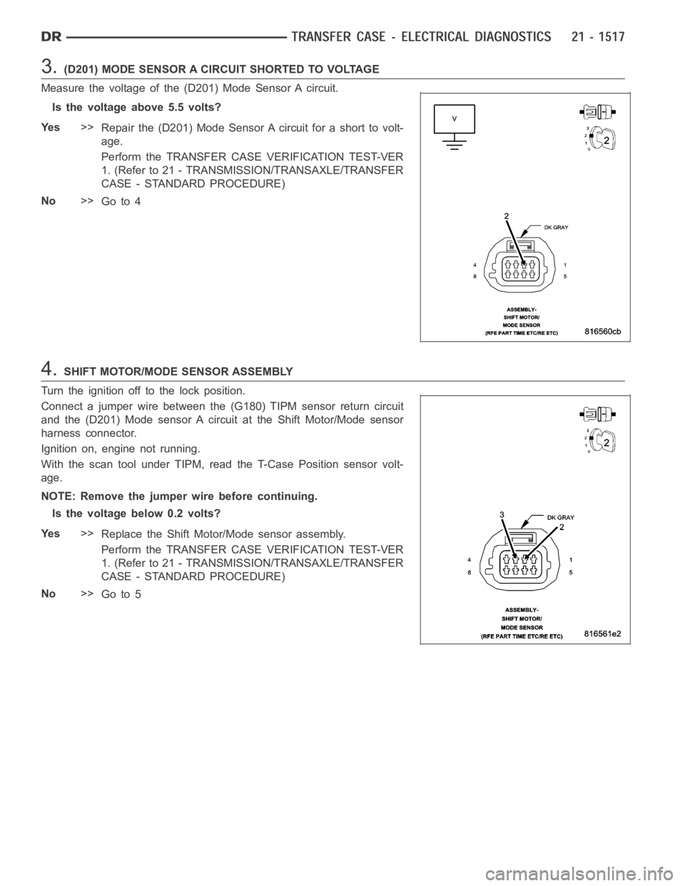
3.(D201) MODE SENSOR A CIRCUIT SHORTED TO VOLTAGE
Measure the voltage of the (D201) Mode Sensor A circuit.
Is the voltage above 5.5 volts?
Ye s>>
Repair the (D201) Mode Sensor A circuit for a short to volt-
age.
Perform the TRANSFER CASE VERIFICATION TEST-VER
1. (Refer to 21 - TRANSMISSION/TRANSAXLE/TRANSFER
CASE - STANDARD PROCEDURE)
No>>
Go to 4
4.SHIFT MOTOR/MODE SENSOR ASSEMBLY
Turn the ignition off to the lock position.
Connect a jumper wire between the (G180) TIPM sensor return circuit
and the (D201) Mode sensor A circuit at the Shift Motor/Mode sensor
harness connector.
Ignition on, engine not running.
With the scan tool under TIPM, read the T-Case Position sensor volt-
age.
NOTE: Remove the jumper wire before continuing.
Is the voltage below 0.2 volts?
Ye s>>
Replace the Shift Motor/Mode sensor assembly.
Perform the TRANSFER CASE VERIFICATION TEST-VER
1. (Refer to 21 - TRANSMISSION/TRANSAXLE/TRANSFER
CASE - STANDARD PROCEDURE)
No>>
Go to 5
Page 4039 of 5267
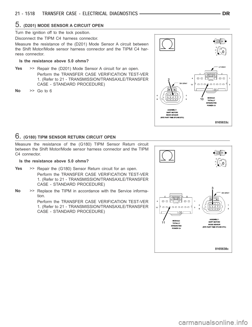
5.(D201) MODE SENSOR A CIRCUIT OPEN
Turn the ignition off to the lock position.
Disconnect the TIPM C4 harness connector.
Measure the resistance of the (D201) Mode Sensor A circuit between
the Shift Motor/Mode sensor harness connector and the TIPM C4 har-
ness connector.
Is the resistance above 5.0 ohms?
Ye s>>
Repair the (D201) Mode Sensor A circuit for an open.
Perform the TRANSFER CASE VERIFICATION TEST-VER
1. (Refer to 21 - TRANSMISSION/TRANSAXLE/TRANSFER
CASE - STANDARD PROCEDURE)
No>>
Go to 6
6.(G180) TIPM SENSOR RETURN CIRCUIT OPEN
Measure the resistance of the (G180) TIPM Sensor Return circuit
between the Shift Motor/Mode sensor harness connector and the TIPM
C4 connector.
Is the resistance above 5.0 ohms?
Ye s>>
Repair the (G180) Sensor Return circuit for an open.
Perform the TRANSFER CASE VERIFICATION TEST-VER
1. (Refer to 21 - TRANSMISSION/TRANSAXLE/TRANSFER
CASE - STANDARD PROCEDURE)
No>>
Replace the TIPM in accordance with the Service informa-
tion.
Perform the TRANSFER CASE VERIFICATION TEST-VER
1. (Refer to 21 - TRANSMISSION/TRANSAXLE/TRANSFER
CASE - STANDARD PROCEDURE)
Page 4040 of 5267
7.INTERMITTENT WIRING AND CONNECTORS
The conditions necessary to set this DTC are not present at this time.
Using the wiring diagram/schematic as a guide, inspect the wiring and connectors.
While monitoring the scan tool data relative to this circuit, wiggle test the wiring and connectors.
Look for the data to change or for the DTC to reset during the wiggle test.
Were any problems found?
Ye s>>
Repair as necessary.
Perform the TRANSFER CASE VERIFICATION TEST-VER 1. (Refer to 21 - TRANSMISSION/TRANS-
AXLE/TRANSFER CASE - STANDARD PROCEDURE)
No>>
Te s t c o m p l e t e .