DODGE RAM SRT-10 2006 Service Repair Manual
Manufacturer: DODGE, Model Year: 2006, Model line: RAM SRT-10, Model: DODGE RAM SRT-10 2006Pages: 5267, PDF Size: 68.7 MB
Page 651 of 5267
When Monitored:
Ignition on and battery voltage above 10.4 volts.
Set Condition:
The signal voltage from the sensor falls below a calibrated value for a calibrated amount of time.
Possible Causes
FUEL LEVEL SENSOR
(N4) SIGNAL CIRCUIT OPEN
(N4) SIGNAL CIRCUIT SHORTED TO VOLTAGE
INTERMITTENT CONDITION
ECM
Always perform the Pre-Diagnostic Troubleshooting procedure before proceeding. (Refer to 9 - ENGINE -
DIAGNOSIS AND TESTING)
Diagnostic Test
1.FUEL LEVEL SENSOR
Turn the ignition off.
Disconnect the Fuel Level Sensor harness connector.
NOTE: Check connectors - Clean/repair as necessary.
Measure the resistance of the sensor across the (N4) signal circuit and (K900) return circuit.
Is the resistance less than 10 ohms?
Ye s>>
Go To 2
No>>
Replace the fuel level sensor.
Perform POWERTRAIN VERIFICATION TEST VER - 1 (DIESEL). (Refer to 8 - ELECTRICAL/ELEC-
TRONIC CONTROL MODULES/ENGINE CONTROL MODULE - DIAGNOSIS AND TESTING)
Page 652 of 5267
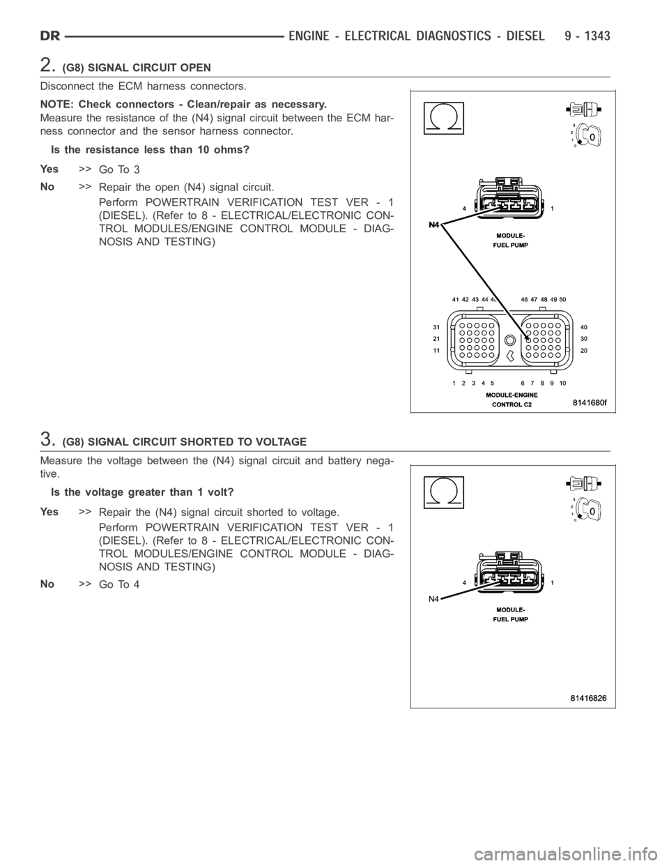
2.(G8) SIGNAL CIRCUIT OPEN
Disconnect the ECM harness connectors.
NOTE: Check connectors - Clean/repair as necessary.
Measure the resistance of the (N4) signal circuit between the ECM har-
ness connector and the sensor harness connector.
Is the resistance less than 10 ohms?
Ye s>>
Go To 3
No>>
Repair the open (N4) signal circuit.
Perform POWERTRAIN VERIFICATION TEST VER - 1
(DIESEL). (Refer to 8 - ELECTRICAL/ELECTRONIC CON-
TROL MODULES/ENGINE CONTROL MODULE - DIAG-
NOSIS AND TESTING)
3.(G8) SIGNAL CIRCUIT SHORTED TO VOLTAGE
Measure the voltage between the (N4) signal circuit and battery nega-
tive.
Is the voltage greater than 1 volt?
Ye s>>
Repair the (N4) signal circuit shorted to voltage.
Perform POWERTRAIN VERIFICATION TEST VER - 1
(DIESEL). (Refer to 8 - ELECTRICAL/ELECTRONIC CON-
TROL MODULES/ENGINE CONTROL MODULE - DIAG-
NOSIS AND TESTING)
No>>
Go To 4
Page 653 of 5267
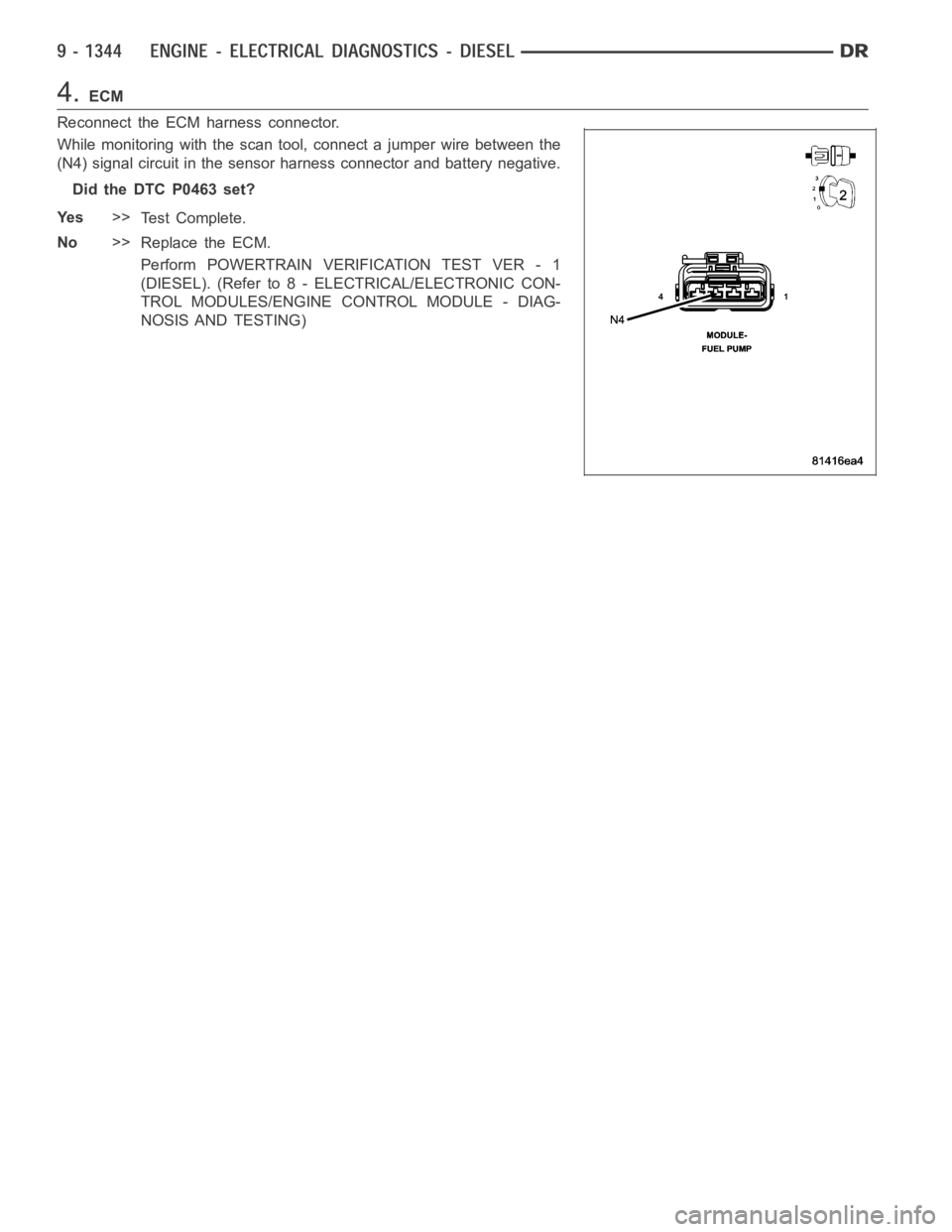
4.ECM
Reconnect the ECM harness connector.
While monitoring with the scan tool, connect a jumper wire between the
(N4) signal circuit in the sensor harness connector and battery negative.
Did the DTC P0463 set?
Ye s>>
Te s t C o m p l e t e .
No>>
Replace the ECM.
Perform POWERTRAIN VERIFICATION TEST VER - 1
(DIESEL). (Refer to 8 - ELECTRICAL/ELECTRONIC CON-
TROL MODULES/ENGINE CONTROL MODULE - DIAG-
NOSIS AND TESTING)
Page 654 of 5267

P0463-HIGH VOLTAGE DETECTED AT THE FUEL LEVEL SENSOR
For a complete wiring diagramRefer to Section 8W.
Page 655 of 5267
When Monitored:
Ignition on and battery voltage above 10.4 volts.
Set Condition:
The signal voltage from the sensor goes above a calibrated value for a calibrated amount of time.
Possible Causes
FUEL LEVEL SENSOR
(N4) SIGNAL CIRCUIT SHORTED TO GROUND
INTERMITTENT CONDITION
ECM
Always perform the Pre-Diagnostic Troubleshooting procedure before proceeding. (Refer to 9 - ENGINE -
DIAGNOSIS AND TESTING)
Diagnostic Test
1.FUEL LEVEL SENSOR
Disconnect the ECM harness connectors.
Disconnect the Fuel level sensor harness connector.
NOTE: Check connectors - Clean/repair as necessary.
Measure the resistance of the Fuel level sensor across the (N4) signal circuit and (K900) return circuit.
Is the resistance less than 10 ohms?
Ye s>>
Go To 2
No>>
Replace the Fuel level sensor.
Perform POWERTRAIN VERIFICATION TEST VER - 1 (DIESEL). (Refer to 8 - ELECTRICAL/ELEC-
TRONIC CONTROL MODULES/ENGINE CONTROL MODULE - DIAGNOSIS AND TESTING)
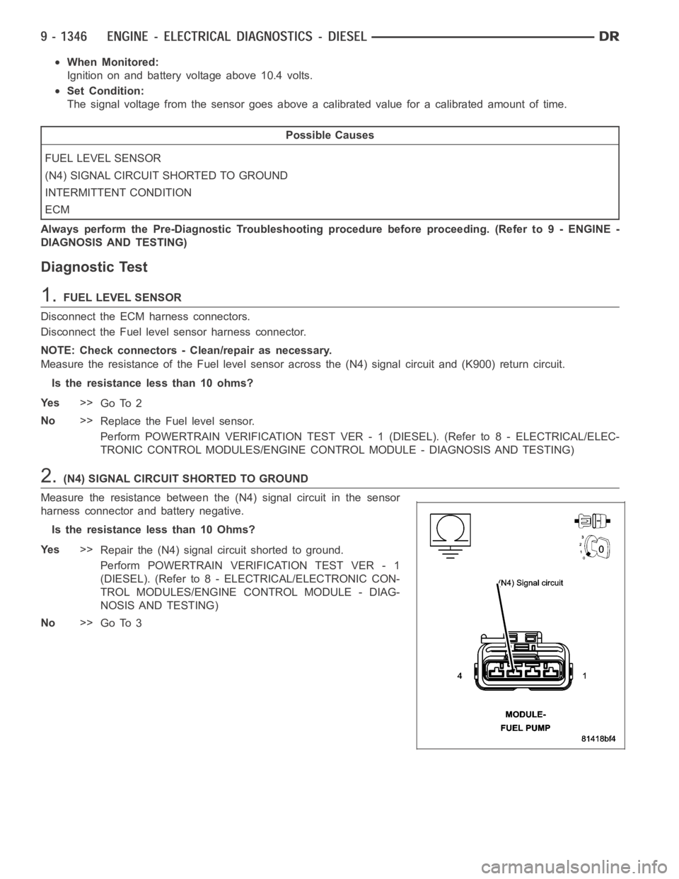
2.(N4) SIGNAL CIRCUIT SHORTED TO GROUND
Measure the resistance between the (N4) signal circuit in the sensor
harness connector and battery negative.
Is the resistance less than 10 Ohms?
Ye s>>
Repair the (N4) signal circuit shorted to ground.
Perform POWERTRAIN VERIFICATION TEST VER - 1
(DIESEL). (Refer to 8 - ELECTRICAL/ELECTRONIC CON-
TROL MODULES/ENGINE CONTROL MODULE - DIAG-
NOSIS AND TESTING)
No>>
Go To 3
Page 656 of 5267

3.ECM
Reconnect the ECM harness connector.
While monitoring with the scan tool, disconnect the Fuel level sensor harness connector.
Did the DTC P0462 set?
Ye s>>
Te s t C o m p l e t e .
No>>
Replace the ECM.
Perform POWERTRAIN VERIFICATION TEST VER - 1 (DIESEL). (Refer to 8 - ELECTRICAL/ELEC-
TRONIC CONTROL MODULES/ENGINE CONTROL MODULE - DIAGNOSIS AND TESTING)
Page 657 of 5267
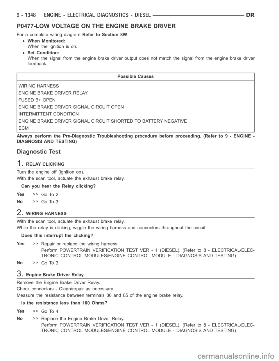
P0477-LOW VOLTAGE ON THE ENGINE BRAKE DRIVER
For a complete wiring diagramRefer to Section 8W.
When Monitored:
When the ignition is on.
Set Condition:
When the signal from the engine brake driver output does not match the signal from the engine brake driver
feedback.
Possible Causes
WIRING HARNESS
ENGINE BRAKE DRIVER RELAY
FUSED B+ OPEN
ENGINE BRAKE DRIVER SIGNAL CIRCUIT OPEN
INTERMITTENT CONDITION
ENGINE BRAKE DRIVER SIGNAL CIRCUIT SHORTED TO BATTERY NEGATIVE
ECM
Always perform the Pre-Diagnostic Troubleshooting procedure before proceeding. (Refer to 9 - ENGINE -
DIAGNOSIS AND TESTING)
Diagnostic Test
1.RELAY CLICKING
Turn the engine off (ignition on).
With the scan tool, actuate the exhaust brake relay.
Can you hear the Relay clicking?
Ye s>>
Go To 2
No>>
Go To 3
2.WIRING HARNESS
With the scan tool, actuate the exhaust brake relay.
While the relay is clicking, wiggle the wiring harness and connectors throughout the circuit.
Does this interrupt the clicking?
Ye s>>
Repair or replace the wiring harness.
Perform POWERTRAIN VERIFICATION TEST VER - 1 (DIESEL). (Refer to 8 - ELECTRICAL/ELEC-
TRONIC CONTROL MODULES/ENGINE CONTROL MODULE - DIAGNOSIS AND TESTING)
No>>
Go To 3
3.Engine Brake Driver Relay
Remove the Engine Brake Driver Relay.
Check connectors - Clean/repair as necessary.
Measure the resistance between terminals 86 and 85 of the engine brake relay.
Is the resistance less than 100 Ohms?
Ye s>>
Go To 4
No>>
Replace the Engine Brake Driver Relay.
Perform POWERTRAIN VERIFICATION TEST VER - 1 (DIESEL). (Refer to 8 - ELECTRICAL/ELEC-
TRONIC CONTROL MODULES/ENGINE CONTROL MODULE - DIAGNOSIS AND TESTING)
Page 658 of 5267
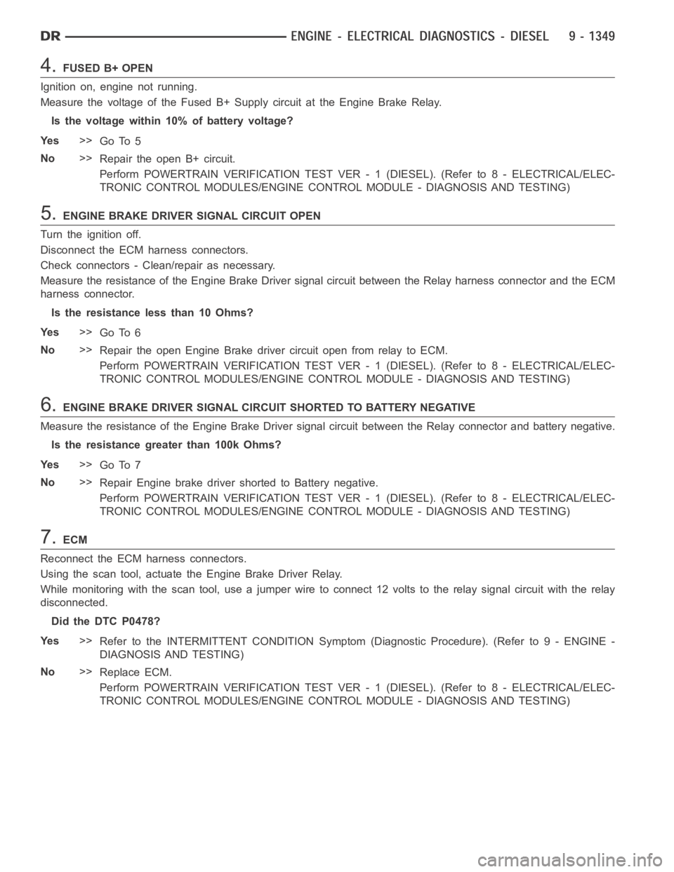
4.FUSED B+ OPEN
Ignition on, engine not running.
Measure the voltage of the Fused B+ Supply circuit at the Engine Brake Relay.
Is the voltage within 10% of battery voltage?
Ye s>>
Go To 5
No>>
Repair the open B+ circuit.
Perform POWERTRAIN VERIFICATION TEST VER - 1 (DIESEL). (Refer to 8 - ELECTRICAL/ELEC-
TRONIC CONTROL MODULES/ENGINE CONTROL MODULE - DIAGNOSIS AND TESTING)
5.ENGINE BRAKE DRIVER SIGNAL CIRCUIT OPEN
Turn the ignition off.
Disconnect the ECM harness connectors.
Check connectors - Clean/repair as necessary.
Measure the resistance of the Engine Brake Driver signal circuit between the Relay harness connector and the ECM
harness connector.
Is the resistance less than 10 Ohms?
Ye s>>
Go To 6
No>>
Repair the open Engine Brake driver circuit open from relay to ECM.
Perform POWERTRAIN VERIFICATION TEST VER - 1 (DIESEL). (Refer to 8 - ELECTRICAL/ELEC-
TRONIC CONTROL MODULES/ENGINE CONTROL MODULE - DIAGNOSIS AND TESTING)
6.ENGINE BRAKE DRIVER SIGNAL CIRCUIT SHORTED TO BATTERY NEGATIVE
Measure the resistance of the Engine Brake Driver signal circuit between the Relay connector and battery negative.
Is the resistance greater than 100k Ohms?
Ye s>>
Go To 7
No>>
Repair Engine brake driver shorted to Battery negative.
Perform POWERTRAIN VERIFICATION TEST VER - 1 (DIESEL). (Refer to 8 - ELECTRICAL/ELEC-
TRONIC CONTROL MODULES/ENGINE CONTROL MODULE - DIAGNOSIS AND TESTING)
7.ECM
Reconnect the ECM harness connectors.
Using the scan tool, actuate the Engine Brake Driver Relay.
While monitoring with the scan tool, use a jumper wire to connect 12 volts tothe relay signal circuit with the relay
disconnected.
Did the DTC P0478?
Ye s>>
Refer to the INTERMITTENT CONDITION Symptom (Diagnostic Procedure). (Refer to 9 - ENGINE -
DIAGNOSIS AND TESTING)
No>>
Replace ECM.
Perform POWERTRAIN VERIFICATION TEST VER - 1 (DIESEL). (Refer to 8 - ELECTRICAL/ELEC-
TRONIC CONTROL MODULES/ENGINE CONTROL MODULE - DIAGNOSIS AND TESTING)
Page 659 of 5267
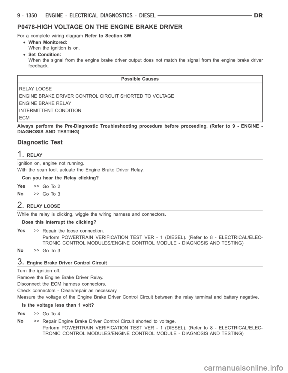
P0478-HIGH VOLTAGE ON THE ENGINE BRAKE DRIVER
For a complete wiring diagramRefer to Section 8W.
When Monitored:
When the ignition is on.
Set Condition:
When the signal from the engine brake driver output does not match the signal from the engine brake driver
feedback.
Possible Causes
RELAY LOOSE
ENGINE BRAKE DRIVER CONTROL CIRCUIT SHORTED TO VOLTAGE
ENGINE BRAKE RELAY
INTERMITTENT CONDITION
ECM
Always perform the Pre-Diagnostic Troubleshooting procedure before proceeding. (Refer to 9 - ENGINE -
DIAGNOSIS AND TESTING)
Diagnostic Test
1.RELAY
Ignition on, engine not running.
With the scan tool, actuate the Engine Brake Driver Relay.
Can you hear the Relay clicking?
Ye s>>
Go To 2
No>>
Go To 3
2.RELAY LOOSE
While the relay is clicking, wiggle the wiring harness and connectors.
Does this interrupt the clicking?
Ye s>>
Repair the loose connection.
Perform POWERTRAIN VERIFICATION TEST VER - 1 (DIESEL). (Refer to 8 - ELECTRICAL/ELEC-
TRONIC CONTROL MODULES/ENGINE CONTROL MODULE - DIAGNOSIS AND TESTING)
No>>
Go To 3
3.Engine Brake Driver Control Circuit
Turn the ignition off.
Remove the Engine Brake Driver Relay.
Disconnect the ECM harness connectors.
Check connectors - Clean/repair as necessary.
Measure the voltage of the Engine Brake Driver Control Circuit between therelay terminal and battery negative.
Is the voltage less than 1 volt?
Ye s>>
Go To 4
No>>
Repair Engine Brake Driver Control Circuit shorted to voltage.
Perform POWERTRAIN VERIFICATION TEST VER - 1 (DIESEL). (Refer to 8 - ELECTRICAL/ELEC-
TRONIC CONTROL MODULES/ENGINE CONTROL MODULE - DIAGNOSIS AND TESTING)
Page 660 of 5267
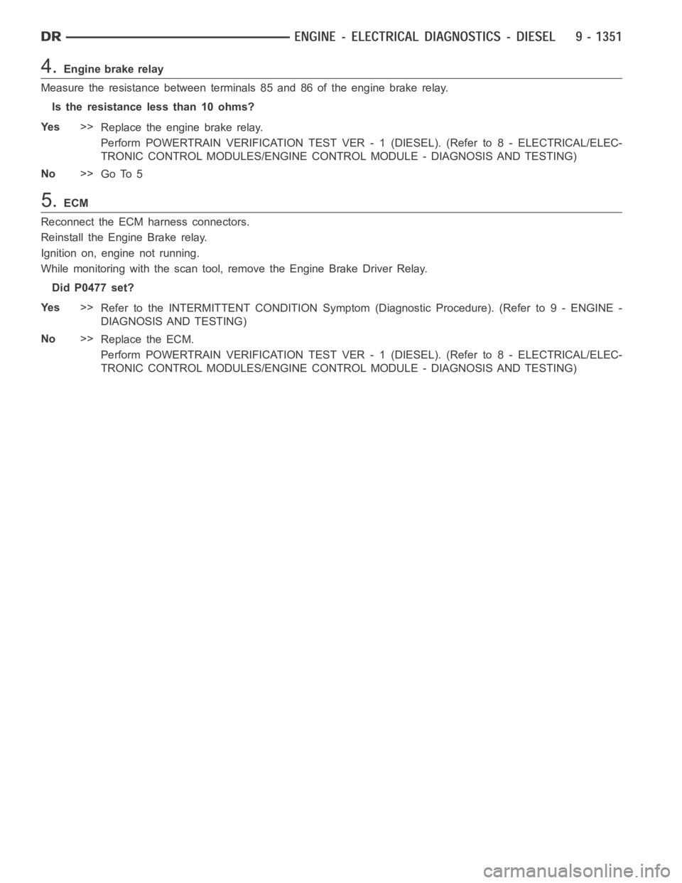
4.Engine brake relay
Measure the resistance between terminals 85 and 86 of the engine brake relay.
Is the resistance less than 10 ohms?
Ye s>>
Replace the engine brake relay.
Perform POWERTRAIN VERIFICATION TEST VER - 1 (DIESEL). (Refer to 8 - ELECTRICAL/ELEC-
TRONIC CONTROL MODULES/ENGINE CONTROL MODULE - DIAGNOSIS AND TESTING)
No>>
Go To 5
5.ECM
Reconnect the ECM harness connectors.
Reinstall the Engine Brake relay.
Ignition on, engine not running.
While monitoring with the scan tool, remove the Engine Brake Driver Relay.
Did P0477 set?
Ye s>>
Refer to the INTERMITTENT CONDITION Symptom (Diagnostic Procedure). (Refer to 9 - ENGINE -
DIAGNOSIS AND TESTING)
No>>
Replace the ECM.
Perform POWERTRAIN VERIFICATION TEST VER - 1 (DIESEL). (Refer to 8 - ELECTRICAL/ELEC-
TRONIC CONTROL MODULES/ENGINE CONTROL MODULE - DIAGNOSIS AND TESTING)