DODGE RAM SRT-10 2006 Service Manual PDF
RAM SRT-10 2006
DODGE
DODGE
https://www.carmanualsonline.info/img/12/56917/w960_56917-0.png
DODGE RAM SRT-10 2006 Service Manual PDF
Page 223 of 5267
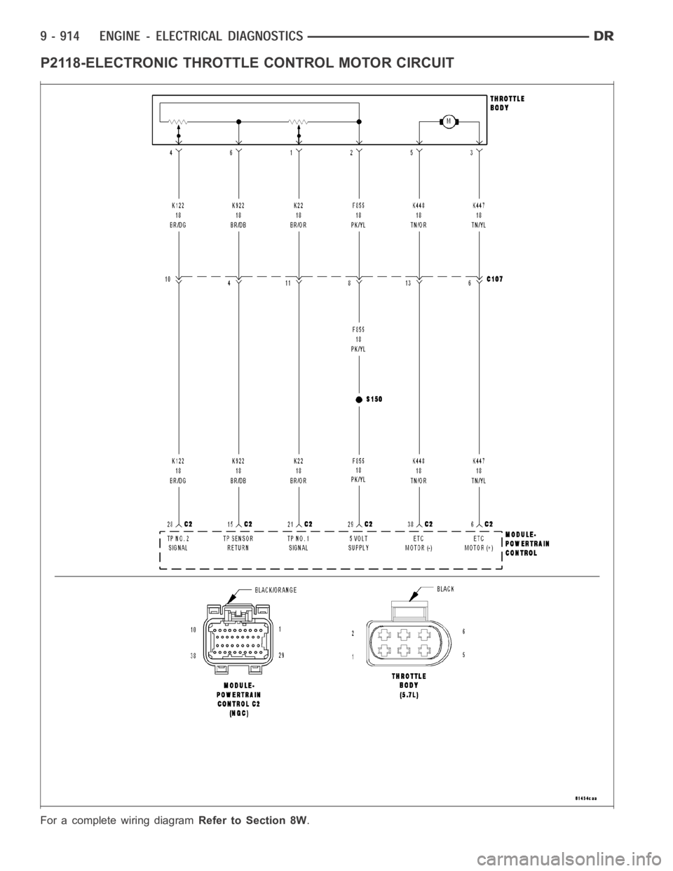
P2118-ELECTRONIC THROTTLE CONTROL MOTOR CIRCUIT
For a complete wiring diagramRefer to Section 8W.
Page 229 of 5267
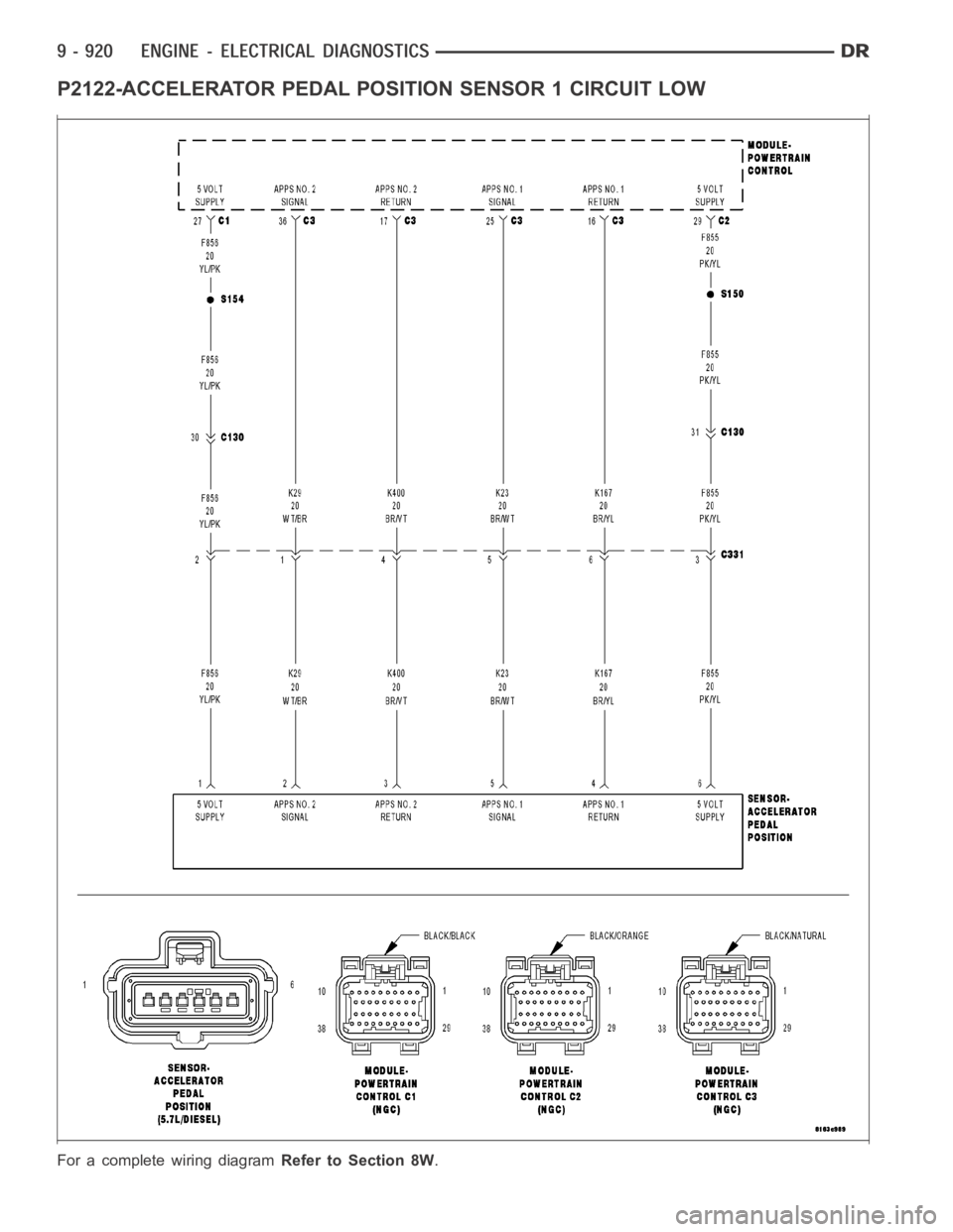
P2122-ACCELERATOR PEDAL POSITION SENSOR 1 CIRCUIT LOW
For a complete wiring diagramRefer to Section 8W.
Page 235 of 5267
P2123-ACCELERATOR PEDAL POSITION SENSOR 1 CIRCUIT HIGH
For a complete wiring diagramRefer to Section 8W.
Page 239 of 5267
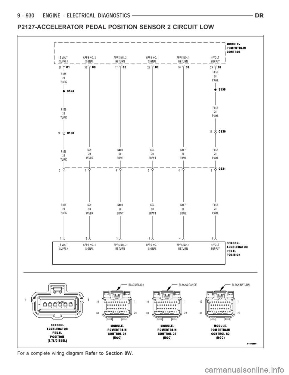
P2127-ACCELERATOR PEDAL POSITION SENSOR 2 CIRCUIT LOW
For a complete wiring diagramRefer to Section 8W.
Page 245 of 5267
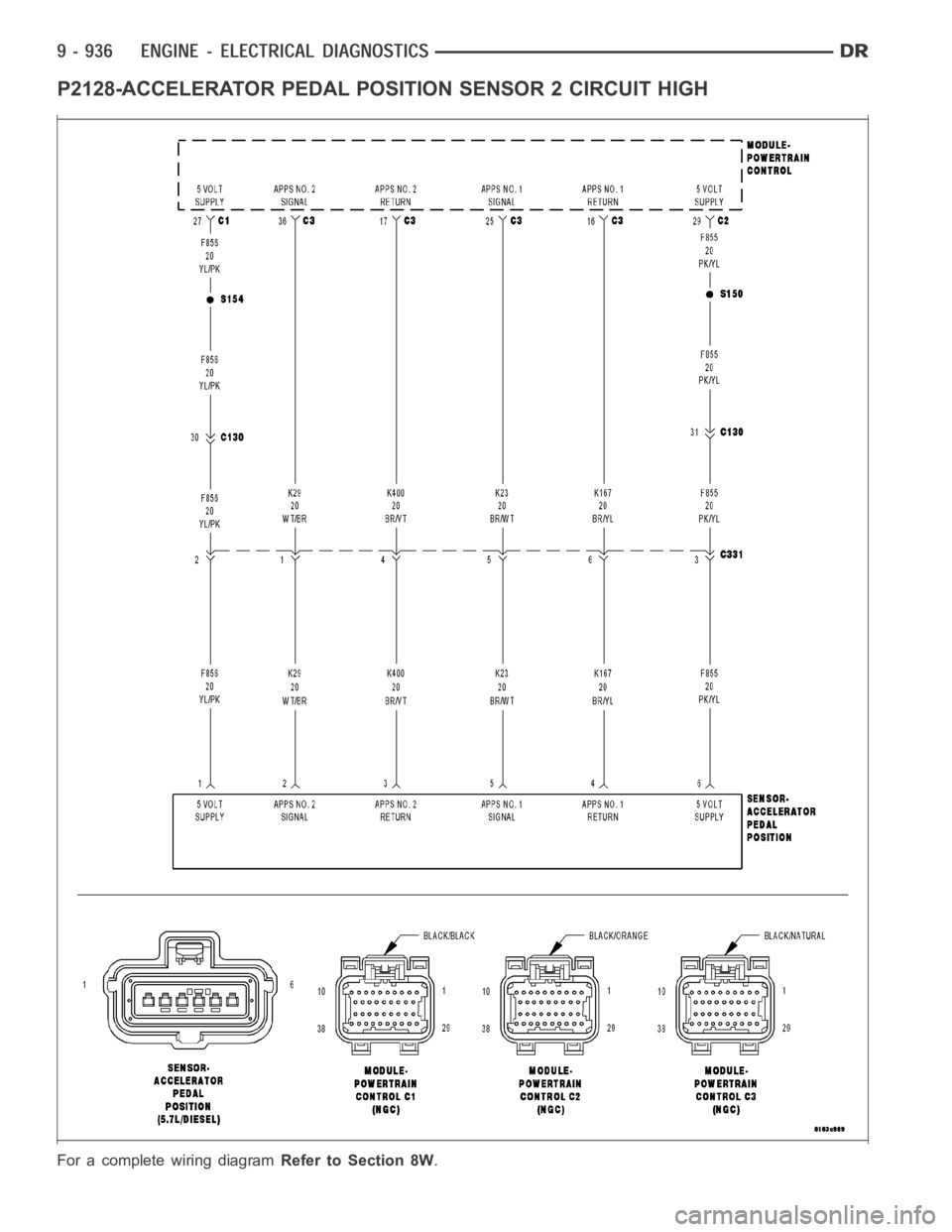
P2128-ACCELERATOR PEDAL POSITION SENSOR 2 CIRCUIT HIGH
For a complete wiring diagramRefer to Section 8W.
Page 249 of 5267
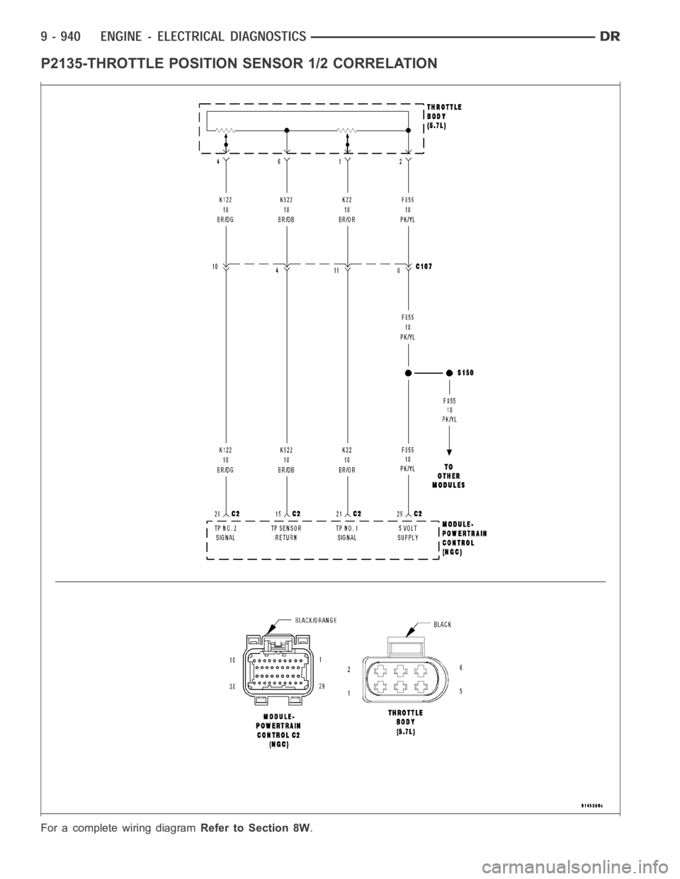
P2135-THROTTLE POSITION SENSOR 1/2 CORRELATION
For a complete wiring diagramRefer to Section 8W.
Page 257 of 5267
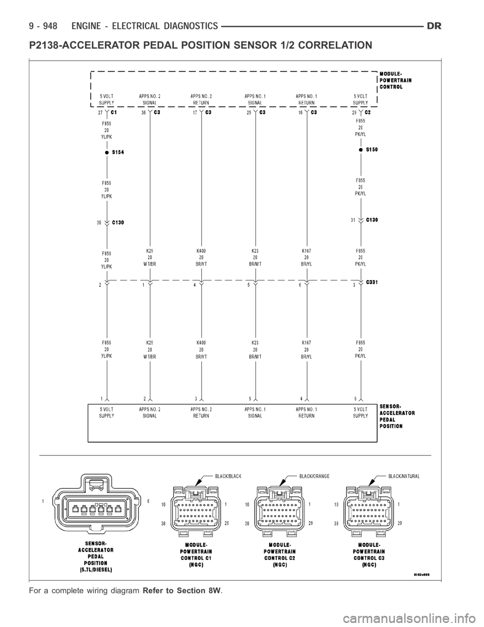
P2138-ACCELERATOR PEDAL POSITION SENSOR 1/2 CORRELATION
For a complete wiring diagramRefer to Section 8W.
Page 263 of 5267
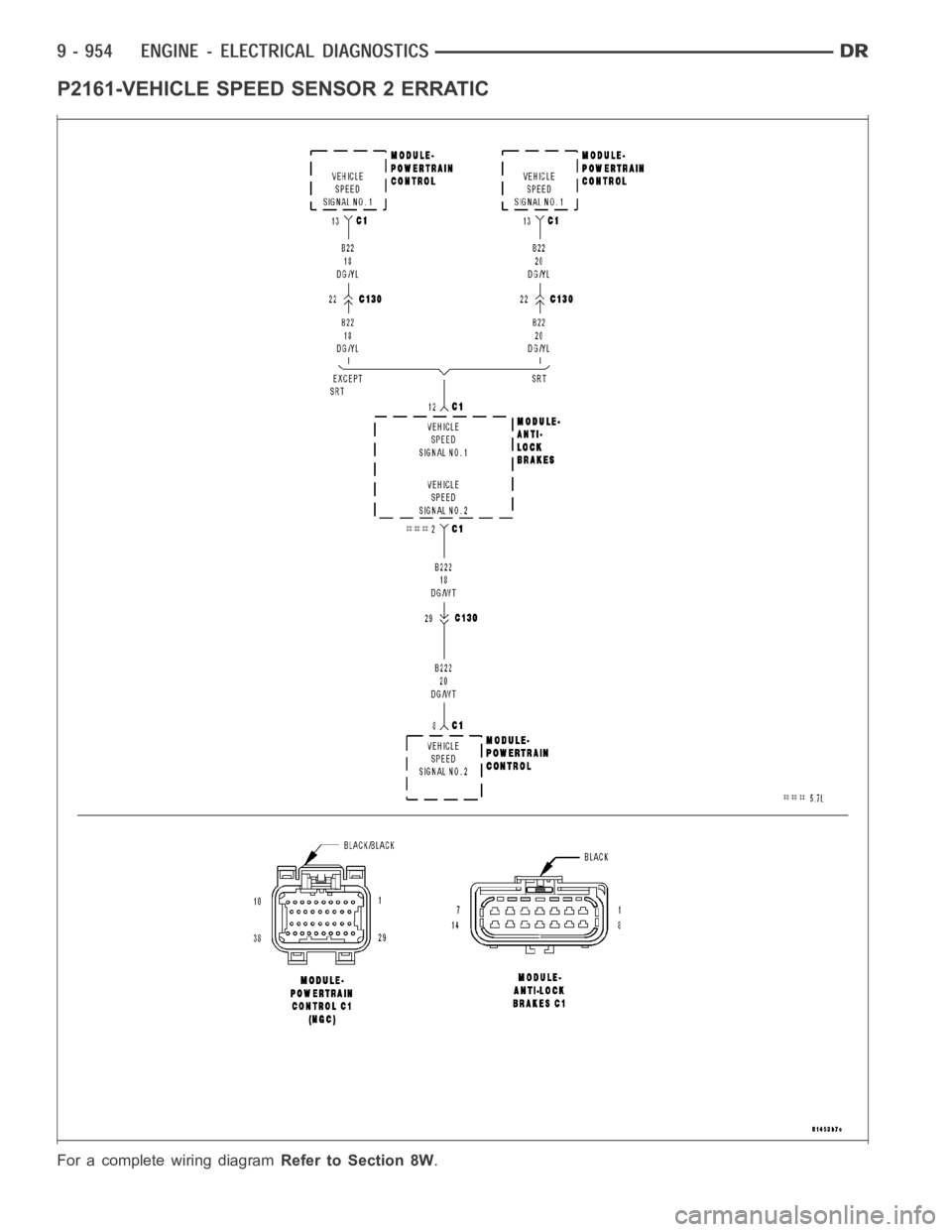
P2161-VEHICLE SPEED SENSOR 2 ERRATIC
For a complete wiring diagramRefer to Section 8W.
Page 267 of 5267
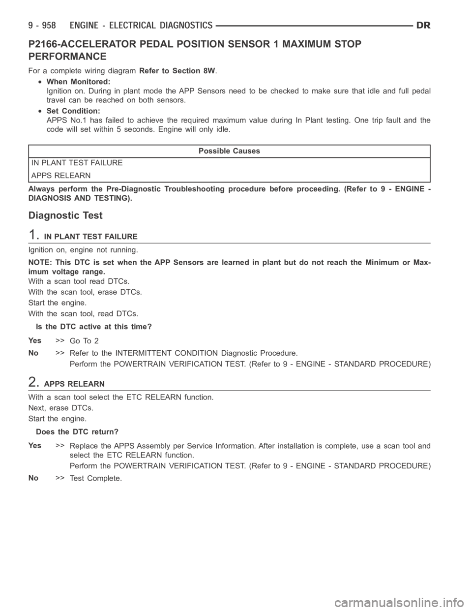
P2166-ACCELERATOR PEDAL POSITION SENSOR 1 MAXIMUM STOP
PERFORMANCE
For a complete wiring diagramRefer to Section 8W.
When Monitored:
Ignition on. During in plant mode the APP Sensors need to be checked to make sure that idle and full pedal
travelcanbereachedonbothsensors.
Set Condition:
APPS No.1 has failed to achieve the required maximum value during In Plant testing. One trip fault and the
code will set within 5 seconds. Engine will only idle.
Possible Causes
IN PLANT TEST FAILURE
APPS RELEARN
Always perform the Pre-Diagnostic Troubleshooting procedure before proceeding. (Refer to 9 - ENGINE -
DIAGNOSIS AND TESTING).
Diagnostic Test
1.IN PLANT TEST FAILURE
Ignition on, engine not running.
NOTE: This DTC is set when the APP Sensors are learned in plant but do not reach the Minimum or Max-
imum voltage range.
With a scan tool read DTCs.
With the scan tool, erase DTCs.
Start the engine.
With the scan tool, read DTCs.
Is the DTC active at this time?
Ye s>>
Go To 2
No>>
Refer to the INTERMITTENT CONDITION Diagnostic Procedure.
Perform the POWERTRAIN VERIFICATION TEST. (Refer to 9 - ENGINE - STANDARD PROCEDURE)
2.APPS RELEARN
With a scan tool select the ETC RELEARN function.
Next, erase DTCs.
Start the engine.
Does the DTC return?
Ye s>>
Replace the APPS Assembly per Service Information. After installation iscomplete, use a scan tool and
select the ETC RELEARN function.
Perform the POWERTRAIN VERIFICATION TEST. (Refer to 9 - ENGINE - STANDARD PROCEDURE)
No>>
Te s t C o m p l e t e .
Page 268 of 5267
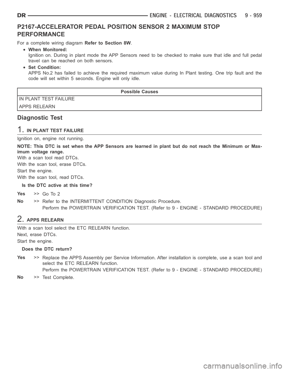
P2167-ACCELERATOR PEDAL POSITION SENSOR 2 MAXIMUM STOP
PERFORMANCE
For a complete wiring diagramRefer to Section 8W.
When Monitored:
Ignition on. During in plant mode the APP Sensors need to be checked to make sure that idle and full pedal
travelcanbereachedonbothsensors.
Set Condition:
APPS No.2 has failed to achieve the required maximum value during In Plant testing. One trip fault and the
code will set within 5 seconds. Engine will only idle.
Possible Causes
IN PLANT TEST FAILURE
APPS RELEARN
Diagnostic Test
1.IN PLANT TEST FAILURE
Ignition on, engine not running.
NOTE: This DTC is set when the APP Sensors are learned in plant but do not reach the Minimum or Max-
imum voltage range.
With a scan tool read DTCs.
With the scan tool, erase DTCs.
Start the engine.
With the scan tool, read DTCs.
Is the DTC active at this time?
Ye s>>
Go To 2
No>>
Refer to the INTERMITTENT CONDITION Diagnostic Procedure.
Perform the POWERTRAIN VERIFICATION TEST. (Refer to 9 - ENGINE - STANDARD PROCEDURE)
2.APPS RELEARN
With a scan tool select the ETC RELEARN function.
Next, erase DTCs.
Start the engine.
Does the DTC return?
Ye s>>
Replace the APPS Assembly per Service Information. After installation iscomplete, use a scan tool and
select the ETC RELEARN function.
Perform the POWERTRAIN VERIFICATION TEST. (Refer to 9 - ENGINE - STANDARD PROCEDURE)
No>>
Te s t C o m p l e t e .