bulb DODGE RAM SRT-10 2006 Service Repair Manual
[x] Cancel search | Manufacturer: DODGE, Model Year: 2006, Model line: RAM SRT-10, Model: DODGE RAM SRT-10 2006Pages: 5267, PDF Size: 68.7 MB
Page 645 of 5267
P0381-WAIT TO START LAMP INOPERATIVE
For a complete wiring diagramRefer to Section 8W.
When Monitored:
Ignition on.
Set Condition:
The cluster sends a signal to the ECM that it has detected a failed wait to start lamp.
Possible Causes
FUSED IGNITION SWITCH OUTPUT CIRCUIT OPEN
WAIT-TO-START LIGHT BULB
WIRING/CONNECTOR PROBLEM
ECM
Always perform the Pre-Diagnostic Troubleshooting procedure before proceeding. (Refer to 9 - ENGINE -
DIAGNOSIS AND TESTING)
Diagnostic Test
1.WAIT-TO-START LAMP DOES NOT COME ON
Turn the ignition off.
While watching the wait-to-start lamp, turn the ignition key on.
Did the wait-to-start lamp light?
Ye s>>
Go To 2
No>>
Go To 3
2.WAIT-TO-START LAMP STAYS ON ALL THE TIME
Turn the ignition off.
While watching the wait-to-start lamp, turn the ignition key on.
Does the wait-to-start lamp stay on all the time?
Ye s>>
Go To 3
No>>
Wait-to-start Lamp operating normally. Test passed.
Perform POWERTRAIN VERIFICATION TEST VER - 1 (DIESEL). (Refer to 8 - ELECTRICAL/ELEC-
TRONIC CONTROL MODULES/ENGINE CONTROL MODULE - DIAGNOSIS AND TESTING)
Page 646 of 5267
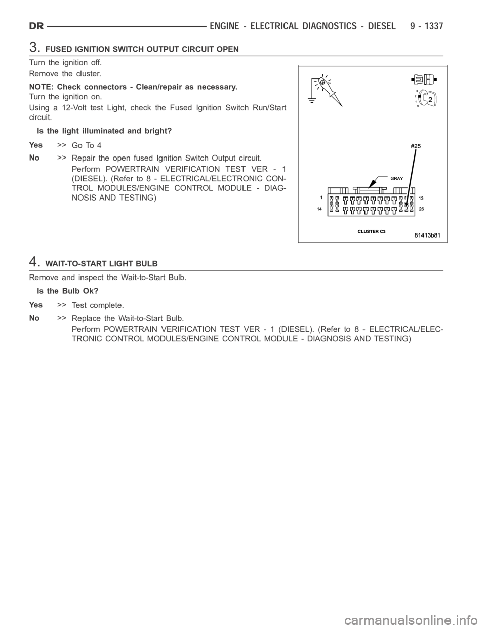
3.FUSED IGNITION SWITCH OUTPUT CIRCUIT OPEN
Turn the ignition off.
Remove the cluster.
NOTE: Check connectors - Clean/repair as necessary.
Turn the ignition on.
Using a 12-Volt test Light, check the Fused Ignition Switch Run/Start
circuit.
Is the light illuminated and bright?
Ye s>>
Go To 4
No>>
Repair the open fused Ignition Switch Output circuit.
Perform POWERTRAIN VERIFICATION TEST VER - 1
(DIESEL). (Refer to 8 - ELECTRICAL/ELECTRONIC CON-
TROL MODULES/ENGINE CONTROL MODULE - DIAG-
NOSIS AND TESTING)
4.WAIT-TO-START LIGHT BULB
Remove and inspect the Wait-to-Start Bulb.
Is the Bulb Ok?
Ye s>>
Te s t c o m p l e t e .
No>>
Replace the Wait-to-Start Bulb.
Perform POWERTRAIN VERIFICATION TEST VER - 1 (DIESEL). (Refer to 8 - ELECTRICAL/ELEC-
TRONIC CONTROL MODULES/ENGINE CONTROL MODULE - DIAGNOSIS AND TESTING)
Page 2348 of 5267
FILTER - FUEL / WATER SEPARATOR
DESCRIPTION
The fuel filter/water separator assembly is located on left side of engineabove the starter motor. The assembly also
includes the fuel heater, Water-In-Fuel (WIF) sensor and a screened banjobolt attached at the bottom of the fuel
filter canister.
OPERATION
The fuel filter/water separator protects the fuel injection pump by removing water and contaminants from the fuel.
The construction of the filter/separator allows fuel to pass through it, but helps prevent moisture (water) from doing
so. Moisture collects at the bottom of the canister.
Refer to the maintenance schedules in the owners manual for the recommended fuel filter replacement intervals.
For draining of water from canister, refer to Fuel Filter/Water SeparatorRemoval/Installation section.
There is a screened banjo bolt that is attached at the bottom of the fuel filter canister. It provides additional filtering
for the high pressure fuel system components.
A Water-In-Fuel (WIF) sensor is attached to the side of fuel filter housing. Refer to Water-In-Fuel Sensor Descrip-
tion/Operation.
The fuel heater is installed into the top of the filter/separator housing.Refer to Fuel Heater Description/Operation.
REMOVAL
Refer to maintenance schedules in this manual, or the
Owner’s Manual for recommended fuel filter replace-
ment intervals.
Draining water from fuel filter/water separator
housing:
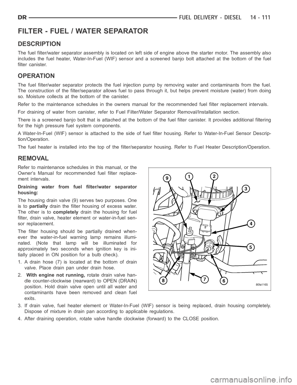
The housing drain valve (9) serves two purposes. One
is topartiallydrain the filter housing of excess water.
The other is tocompletelydrain the housing for fuel
filter, drain valve, heater element or water-in-fuel sen-
sor replacement.
The filter housing should be partially drained when-
ever the water-in-fuel warning lamp remains illumi-
nated. (Note that lamp will be illuminated for
approximately two seconds when ignition key is ini-
tially placed in ON position for a bulb check).
1. A drain hose (7) is located at the bottom of drain
valve. Place drain pan under drain hose.
2.With engine not running,rotate drain valve han-
dle counter-clockwise (rearward) to OPEN (DRAIN)
position. Hold drain valve open until all water and
contaminants have been removed and clean fuel
exits.
3. If drain valve, fuel heater element or Water-In-Fuel (WIF) sensor is being replaced, drain housing completely.
Dispose of mixture in drain pan according to applicable regulations.
4. After draining operation, rotate valve handle clockwise (forward) to the CLOSE position.
Page 4643 of 5267
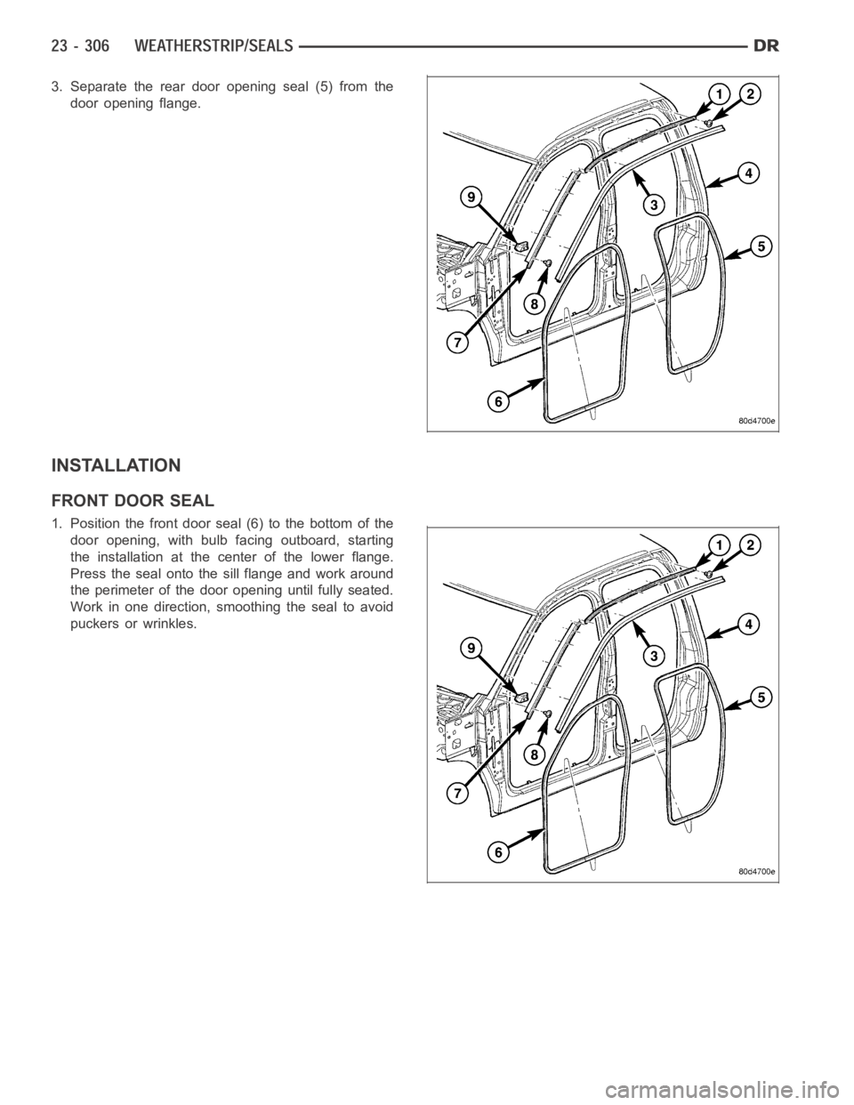
3. Separate the rear door opening seal (5) from the
door opening flange.
INSTALLATION
FRONT DOOR SEAL
1. Position the front door seal (6) to the bottom of the
door opening, with bulb facing outboard, starting
the installation at the center of the lower flange.
Press the seal onto the sill flange and work around
the perimeter of the door opening until fully seated.
Work in one direction, smoothing the seal to avoid
puckers or wrinkles.
Page 4645 of 5267
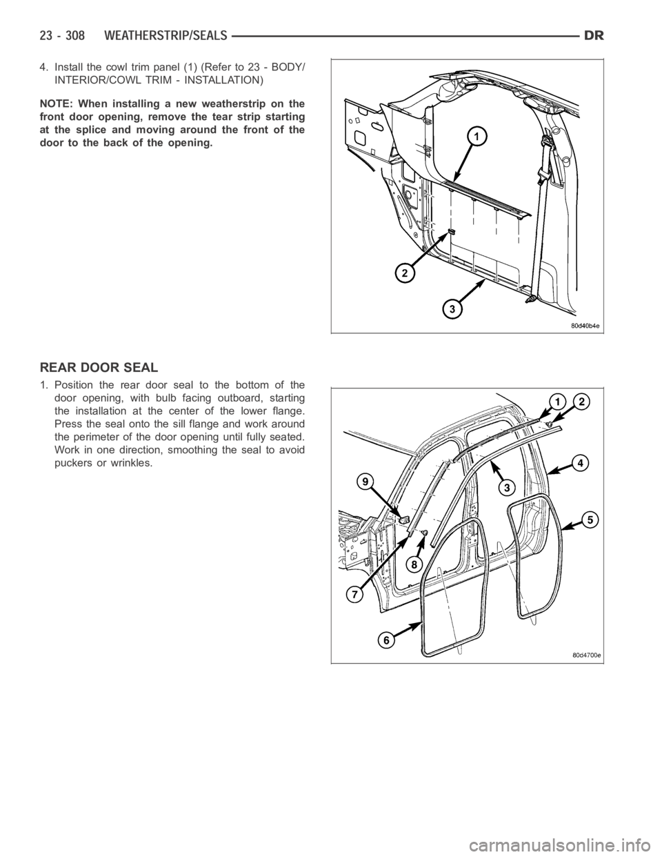
4. Install the cowl trim panel (1) (Refer to 23 - BODY/
INTERIOR/COWL TRIM - INSTALLATION)
NOTE: When installing a new weatherstrip on the
front door opening, remove the tear strip starting
at the splice and moving around the front of the
door to the back of the opening.
REAR DOOR SEAL
1. Position the rear door seal to the bottom of the
door opening, with bulb facing outboard, starting
the installation at the center of the lower flange.
Press the seal onto the sill flange and work around
the perimeter of the door opening until fully seated.
Work in one direction, smoothing the seal to avoid
puckers or wrinkles.
Page 5193 of 5267
EMISSIONS CONTROL
DESCRIPTION
STATE DISPLAY TEST MODE
The switch inputs to the Powertrain Control Module (PCM) have two recognized states; HIGH and LOW. For this
reason, the PCM cannot recognize the difference between a selected switchposition versus an open circuit, a short
circuit, or a defective switch. If the State Display screen shows the changefromHIGHtoLOWorLOWtoHIGH,
assume the entire switch circuit to the PCM functions properly. Connect the DRB scan tool to the data link con-
nector and access the state display screen. Then access either State Display Inputs and Outputs or State Display
Sensors.
CIRCUIT ACTUATION TEST MODE
The Circuit Actuation Test Mode checks for proper operation of output circuits or devices the Powertrain Control
Module (PCM) may not internally recognize. The PCM attempts to activate these outputs and allow an observer to
verify proper operation. Most of the tests provide an audible or visual indication of device operation (click of relay
contacts, fuel spray, etc.). Except for intermittent conditions, if a device functions properly during testing, assume the
device, its associated wiring, and driver circuit work correctly. Connect the DRB scan tool to the data link connector
and access the Actuators screen.
DIAGNOSTIC TROUBLE CODES
A Diagnostic Trouble Code (DTC) indicates the PCM has recognized an abnormal condition in the system.
Remember that DTC’s are the results of a system or circuit failure, but do not directly identify the failed
component or components.
BULB CHECK
Each time the ignition key is turned to the ON position, the malfunction indicator (check engine) lamp on the instru-
ment panel should illuminate for approximately 2 seconds then go out. Thisis done for a bulb check.
OBTAINING DTC’S USING DRB SCAN TOOL
1. Obtain the applicable Powertrain Diagnostic Manual.
2. Obtain the DRB Scan Tool.
3. Connect the DRB Scan Tool to the data link (diagnostic) connector. This connector is located in the passenger
compartment at the lower edge of instrument panel, and near the steering column.
4. Turn the ignition switch on and access the “Read Fault” screen.
5. Record all the DTC’s and “freeze frame” information shown on the DRB scantool.
6. To erase DTC’s, use the “Erase Trouble Code” data screen on the DRB scan tool.Do not erase any DTC’s
until problems have been investigated and repairs have been performed.
TA S K M A N A G E R
The PCM is responsible for efficiently coordinating the operation of all the emissions-related components. The PCM
is also responsible for determining if the diagnostic systems are operating properly. The software designed to carry
out these responsibilities is called the ’Task Manager’.
MONITORED SYSTEMS
There are new electronic circuit monitors that check fuel, emission, engine and ignition performance. These moni-
tors use information from various sensor circuits to indicate the overalloperation of the fuel, engine, ignition and
emission systems and thus the emissions performance of the vehicle.
The fuel, engine, ignition and emission systems monitors do not indicate aspecific component problem. They do
indicate that there is an implied problem within one of the systems and thata specific problem must be diagnosed.
If any of these monitors detect a problem affecting vehicle emissions, theMalfunction Indicator Lamp (MIL) will be
illuminated. These monitors generate Diagnostic Trouble Codes that can be displayed with the MIL or a scan tool.