height DODGE RAM SRT-10 2006 Service Repair Manual
[x] Cancel search | Manufacturer: DODGE, Model Year: 2006, Model line: RAM SRT-10, Model: DODGE RAM SRT-10 2006Pages: 5267, PDF Size: 68.7 MB
Page 1507 of 5267
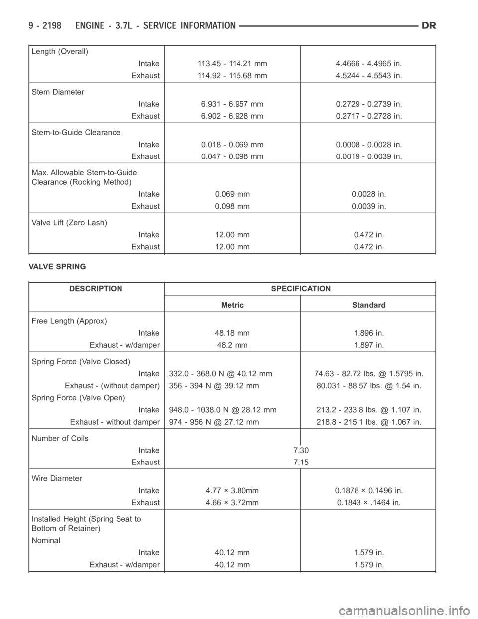
Length (Overall)
Intake 113.45 - 114.21 mm 4.4666 - 4.4965 in.
Exhaust 114.92 - 115.68 mm 4.5244 - 4.5543 in.
Stem Diameter
Intake 6.931 - 6.957 mm 0.2729 - 0.2739 in.
Exhaust 6.902 - 6.928 mm 0.2717 - 0.2728 in.
Stem-to-Guide Clearance
Intake 0.018 - 0.069 mm 0.0008 - 0.0028 in.
Exhaust 0.047 - 0.098 mm 0.0019 - 0.0039 in.
Max. Allowable Stem-to-Guide
Clearance (Rocking Method)
Intake 0.069 mm 0.0028 in.
Exhaust 0.098 mm 0.0039 in.
Valve Lift (Zero Lash)
Intake 12.00 mm 0.472 in.
Exhaust 12.00 mm 0.472 in.
VALVE SPRING
DESCRIPTION SPECIFICATION
Metric Standard
Free Length (Approx)
Intake 48.18 mm 1.896 in.
Exhaust - w/damper 48.2 mm 1.897 in.
Spring Force (Valve Closed)
Intake 332.0 - 368.0 N @ 40.12 mm 74.63 - 82.72 lbs. @ 1.5795 in.
Exhaust - (without damper) 356 - 394 N @ 39.12 mm 80.031 - 88.57 lbs. @ 1.54 in.
Spring Force (Valve Open)
Intake 948.0 - 1038.0 N @ 28.12 mm 213.2 - 233.8 lbs. @ 1.107 in.
Exhaust - without damper 974 - 956 N @ 27.12 mm 218.8 - 215.1 lbs. @ 1.067 in.
Number of Coils
Intake 7.30
Exhaust 7.15
Wire Diameter
Intake 4.77 × 3.80mm 0.1878 × 0.1496 in.
Exhaust 4.66 × 3.72mm 0.1843 × .1464 in.
Installed Height (Spring Seat to
Bottom of Retainer)
Nominal
Intake 40.12 mm 1.579 in.
Exhaust - w/damper 40.12 mm 1.579 in.
Page 1528 of 5267
VALVES & SEATS - INTAKE/EXHAUST
DESCRIPTION
The valves are made of heat resistant steel and have chrome plated stems to prevent scuffing. Each valve is actu-
ated by a roller rocker arm which pivots on a stationary lash adjuster. All valves use three bead lock keepers to
retain the springs and promote valve rotation.
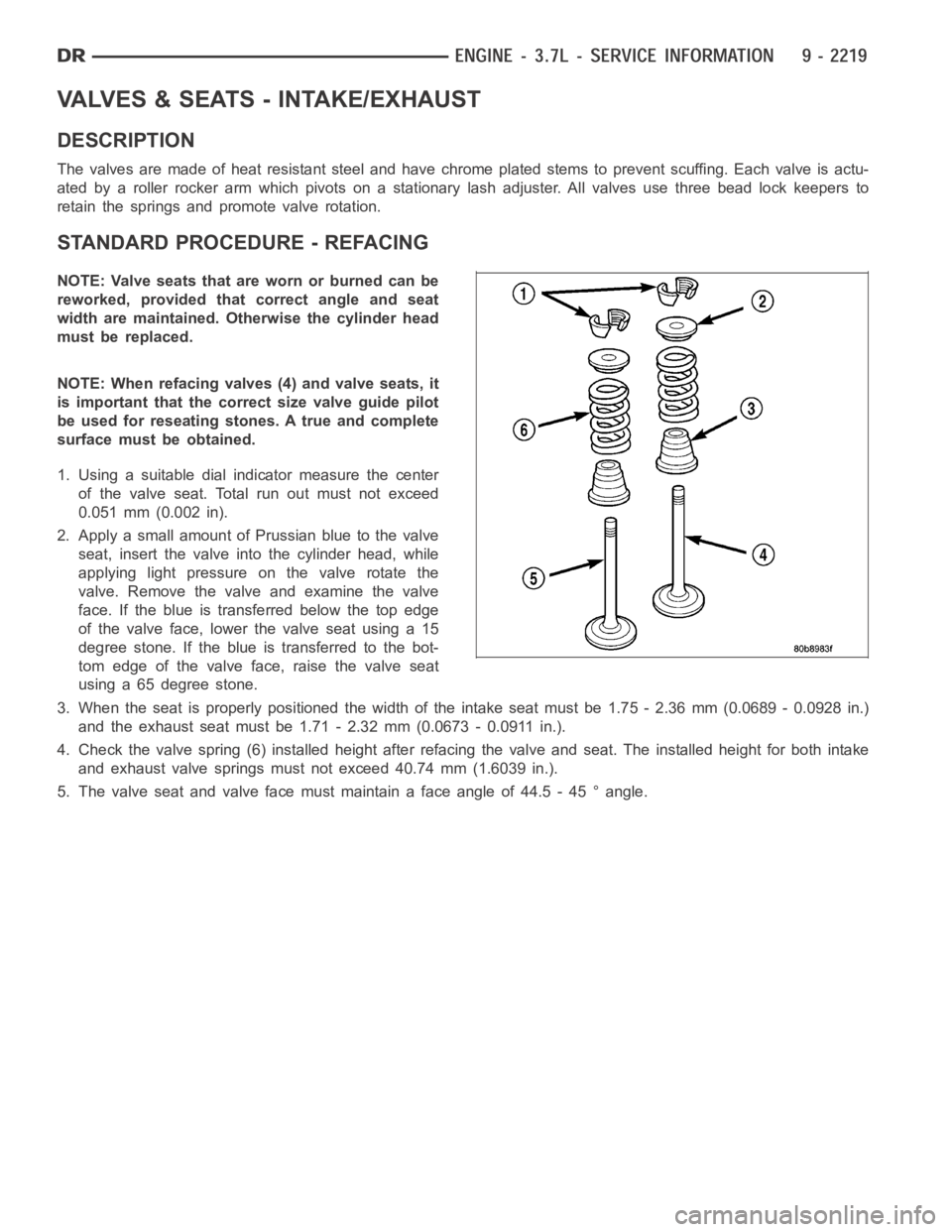
STANDARD PROCEDURE - REFACING
NOTE: Valve seats that are worn or burned can be
reworked, provided that correct angle and seat
width are maintained. Otherwise the cylinder head
must be replaced.
NOTE: When refacing valves (4) and valve seats, it
is important that the correct size valve guide pilot
be used for reseating stones. A true and complete
surface must be obtained.
1. Using a suitable dial indicator measure the center
of the valve seat. Total run out must not exceed
0.051 mm (0.002 in).
2. Apply a small amount of Prussian blue to the valve
seat, insert the valve into the cylinder head, while
applying light pressure on the valve rotate the
valve. Remove the valve and examine the valve
face. If the blue is transferred below the top edge
of the valve face, lower the valve seat using a 15
degree stone. If the blue is transferred to the bot-
tom edge of the valve face, raise the valve seat
using a 65 degree stone.
3. When the seat is properly positioned the width of the intake seat must be 1.75 - 2.36 mm (0.0689 - 0.0928 in.)
and the exhaust seat must be 1.71 - 2.32 mm (0.0673 - 0.0911 in.).
4. Check the valve spring (6) installed height after refacing the valve andseat. The installed height for both intake
and exhaust valve springs must not exceed 40.74 mm (1.6039 in.).
5. The valve seat and valve face must maintain a face angle of 44.5 - 45 ° angle.
Page 1529 of 5267
REMOVAL
NOTE: The cylinder heads must be removed in
order to perform this procedure.
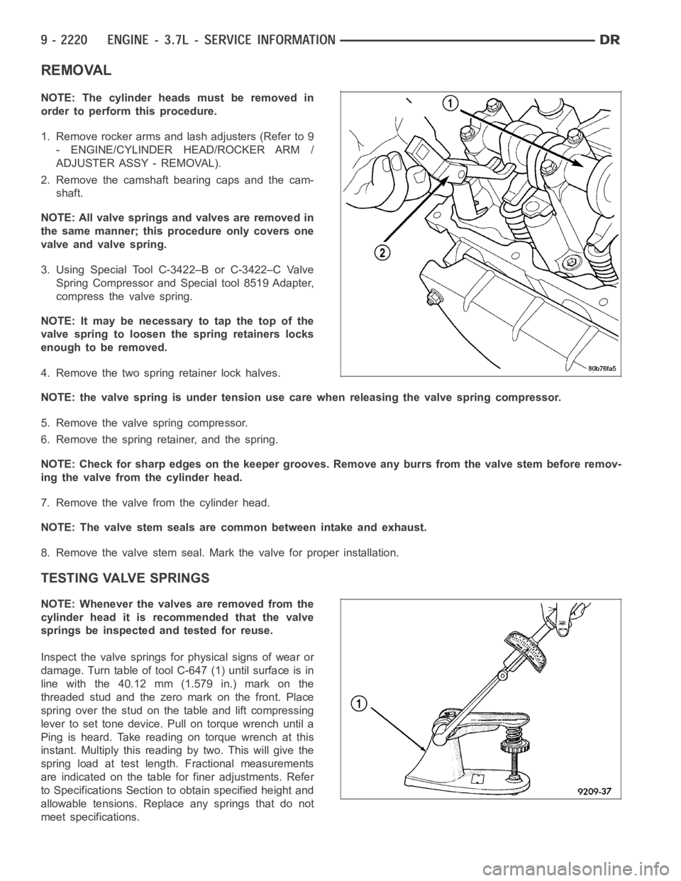
1. Remove rocker arms and lash adjusters (Refer to 9
- ENGINE/CYLINDER HEAD/ROCKER ARM /
ADJUSTER ASSY - REMOVAL).
2. Remove the camshaft bearing caps and the cam-
shaft.
NOTE: All valve springs and valves are removed in
the same manner; this procedure only covers one
valve and valve spring.
3. Using Special Tool C-3422–B or C-3422–C Valve
Spring Compressor and Special tool 8519 Adapter,
compress the valve spring.
NOTE: It may be necessary to tap the top of the
valve spring to loosen the spring retainers locks
enough to be removed.
4. Remove the two spring retainer lock halves.
NOTE: the valve spring is under tension use care when releasing the valve spring compressor.
5. Remove the valve spring compressor.
6. Remove the spring retainer, and the spring.
NOTE: Check for sharp edges on the keeper grooves. Remove any burrs from thevalvestembeforeremov-
ing the valve from the cylinder head.
7. Remove the valve from the cylinder head.
NOTE: The valve stem seals are common between intake and exhaust.
8. Remove the valve stem seal. Mark the valve for proper installation.
TESTING VALVE SPRINGS
NOTE: Whenever the valves are removed from the
cylinder head it is recommended that the valve
springs be inspected and tested for reuse.
Inspect the valve springs for physical signs of wear or
damage. Turn table of tool C-647 (1) until surface is in
line with the 40.12 mm (1.579 in.) mark on the
threaded stud and the zero mark on the front. Place
spring over the stud on the table and lift compressing
lever to set tone device. Pull on torque wrench until a
Ping is heard. Take reading on torque wrench at this
instant. Multiply this reading by two. This will give the
spring load at test length. Fractional measurements
are indicated on the table for finer adjustments. Refer
to Specifications Section to obtain specified height and
allowable tensions. Replace any springs that do not
meet specifications.
Page 1644 of 5267
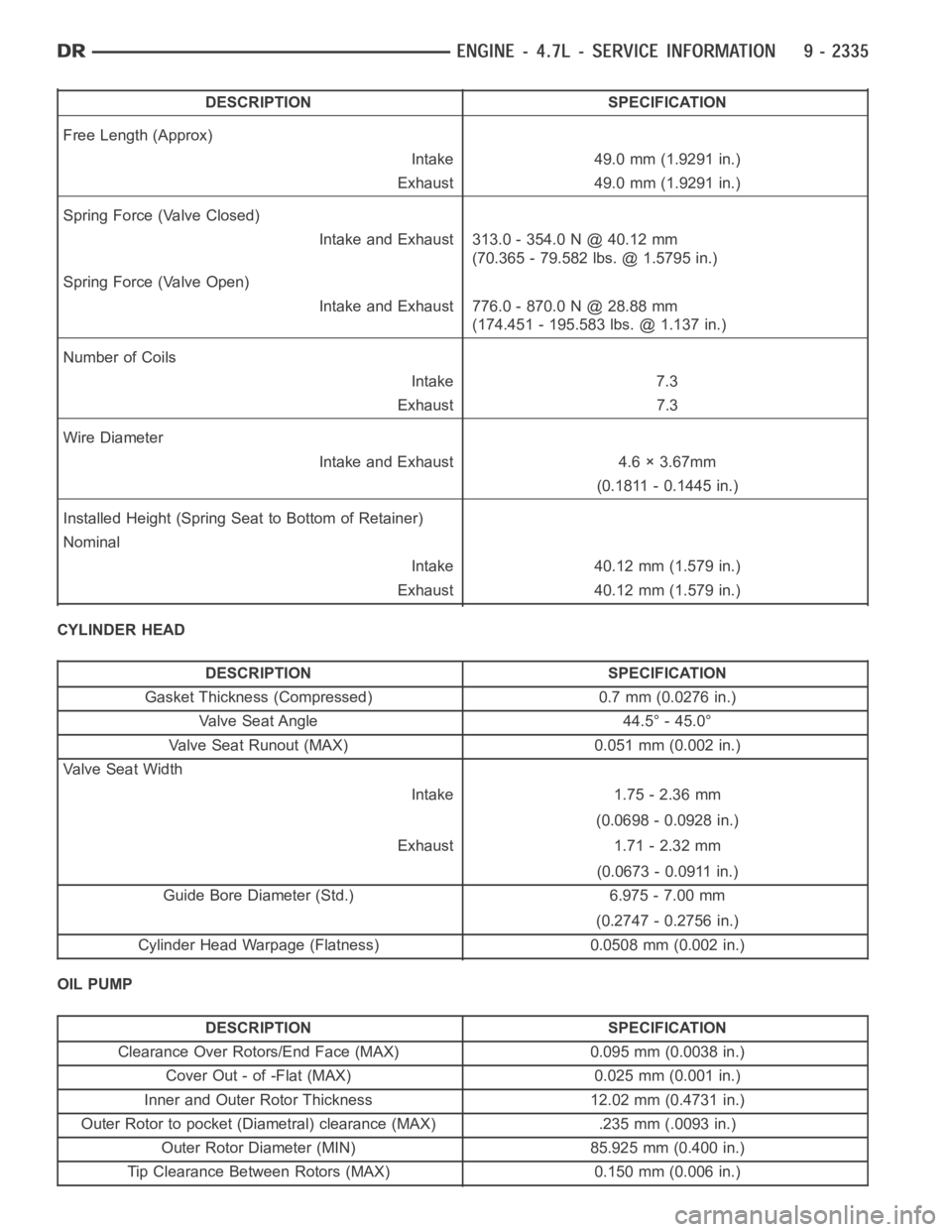
DESCRIPTION SPECIFICATION
Free Length (Approx)
Intake 49.0 mm (1.9291 in.)
Exhaust 49.0 mm (1.9291 in.)
Spring Force (Valve Closed)
Intake and Exhaust 313.0 - 354.0 N @ 40.12 mm
(70.365 - 79.582 lbs. @ 1.5795 in.)
Spring Force (Valve Open)
Intake and Exhaust 776.0 - 870.0 N @ 28.88 mm
(174.451 - 195.583 lbs. @ 1.137 in.)
Number of Coils
Intake 7.3
Exhaust 7.3
Wire Diameter
Intake and Exhaust 4.6 × 3.67mm
(0.1811 - 0.1445 in.)
Installed Height (Spring Seat to Bottom of Retainer)
Nominal
Intake 40.12 mm (1.579 in.)
Exhaust 40.12 mm (1.579 in.)
CYLINDER HEAD
DESCRIPTION SPECIFICATION
Gasket Thickness (Compressed) 0.7 mm (0.0276 in.)
Valve Seat Angle 44.5° - 45.0°
Valve Seat Runout (MAX) 0.051 mm (0.002 in.)
Va l v e S e a t W i d t h
Intake 1.75 - 2.36 mm
(0.0698 - 0.0928 in.)
Exhaust 1.71 - 2.32 mm
(0.0673 - 0.0911 in.)
Guide Bore Diameter (Std.) 6.975 - 7.00 mm
(0.2747 - 0.2756 in.)
Cylinder Head Warpage (Flatness) 0.0508 mm (0.002 in.)
OIL PUMP
DESCRIPTION SPECIFICATION
Clearance Over Rotors/End Face (MAX) 0.095 mm (0.0038 in.)
Cover Out - of -Flat (MAX) 0.025 mm (0.001 in.)
Inner and Outer Rotor Thickness 12.02 mm (0.4731 in.)
Outer Rotor to pocket (Diametral) clearance (MAX) .235 mm (.0093 in.)
Outer Rotor Diameter (MIN) 85.925 mm (0.400 in.)
Tip Clearance Between Rotors (MAX) 0.150 mm (0.006 in.)
Page 1681 of 5267
TESTING VALVE SPRINGS
NOTE: Whenever the valves are removed from the
cylinder head it is recommended that the valve
springs be inspected and tested for reuse.
Inspect the valve springs for physical signs of wear or
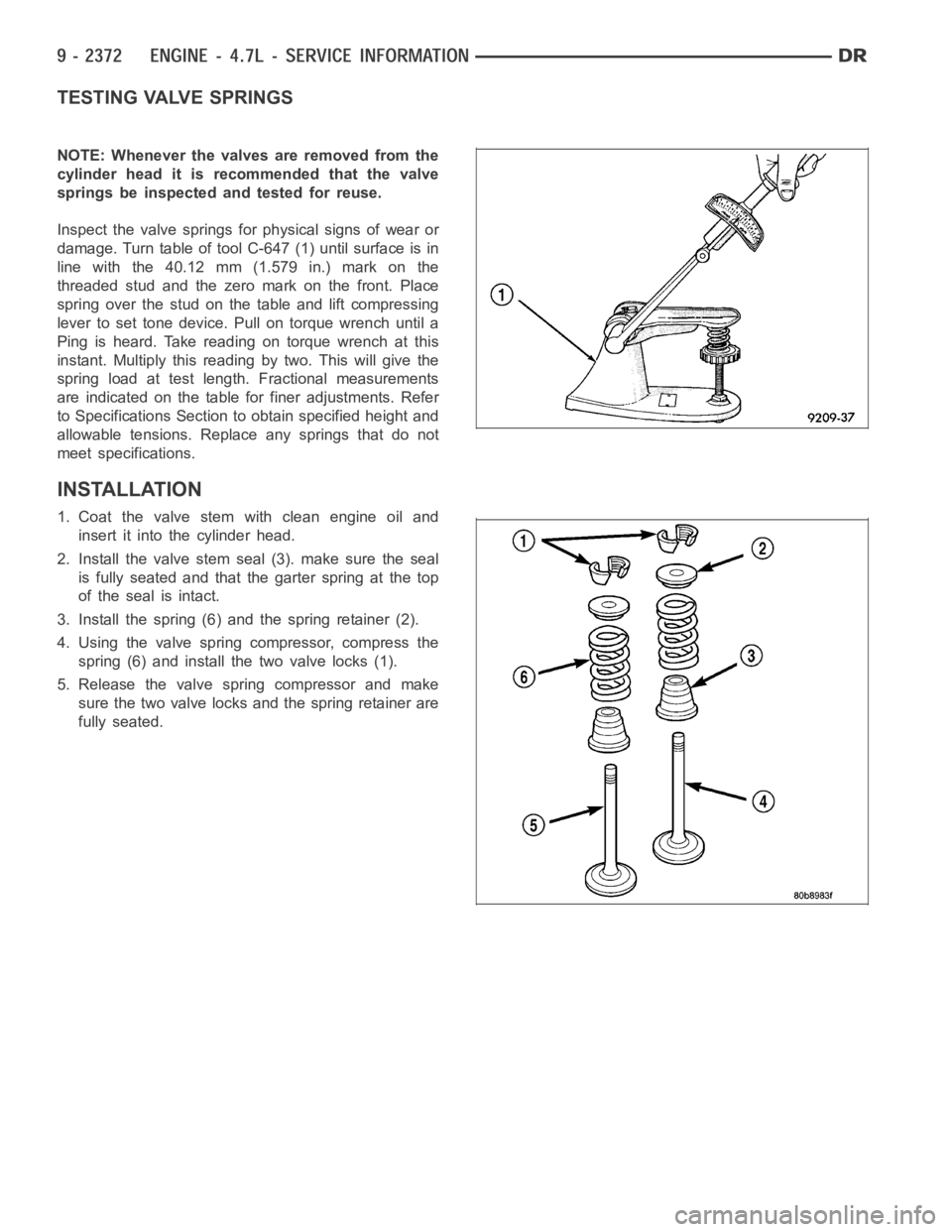
damage. Turn table of tool C-647 (1) until surface is in
line with the 40.12 mm (1.579 in.) mark on the
threaded stud and the zero mark on the front. Place
spring over the stud on the table and lift compressing
lever to set tone device. Pull on torque wrench until a
Ping is heard. Take reading on torque wrench at this
instant. Multiply this reading by two. This will give the
spring load at test length. Fractional measurements
are indicated on the table for finer adjustments. Refer
to Specifications Section to obtain specified height and
allowable tensions. Replace any springs that do not
meet specifications.
INSTALLATION
1. Coat the valve stem with clean engine oil and
insert it into the cylinder head.
2. Install the valve stem seal (3). make sure the seal
is fully seated and that the garter spring at the top
of the seal is intact.
3. Install the spring (6) and the spring retainer (2).
4. Using the valve spring compressor, compress the
spring (6) and install the two valve locks (1).
5. Release the valve spring compressor and make
sure the two valve locks and the spring retainer are
fully seated.
Page 1780 of 5267
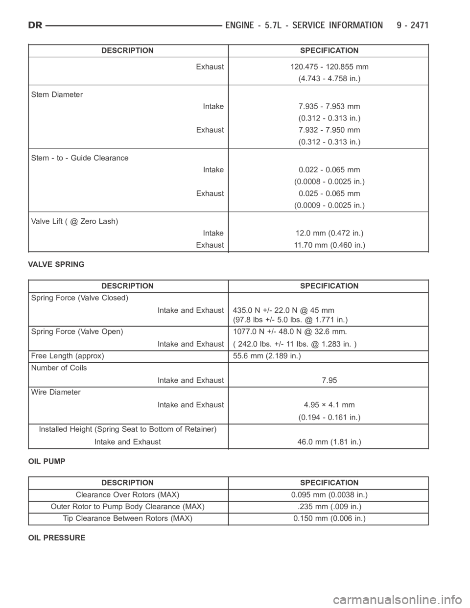
DESCRIPTION SPECIFICATION
Exhaust 120.475 - 120.855 mm
(4.743 - 4.758 in.)
Stem Diameter
Intake 7.935 - 7.953 mm
(0.312 - 0.313 in.)
Exhaust 7.932 - 7.950 mm
(0.312 - 0.313 in.)
Stem - to - Guide Clearance
Intake 0.022 - 0.065 mm
(0.0008 - 0.0025 in.)
Exhaust 0.025 - 0.065 mm
(0.0009 - 0.0025 in.)
ValveLift(@ZeroLash)
Intake 12.0 mm (0.472 in.)
Exhaust 11.70 mm (0.460 in.)
VALVE SPRING
DESCRIPTION SPECIFICATION
Spring Force (Valve Closed)
Intake and Exhaust 435.0 N +/- 22.0 N @ 45 mm
(97.8 lbs +/- 5.0 lbs. @ 1.771 in.)
Spring Force (Valve Open) 1077.0 N +/- 48.0 N @ 32.6 mm.
Intake and Exhaust ( 242.0 lbs. +/- 11 lbs. @ 1.283 in. )
Free Length (approx) 55.6 mm (2.189 in.)
Number of Coils
Intake and Exhaust 7.95
Wire Diameter
Intake and Exhaust 4.95 × 4.1 mm
(0.194 - 0.161 in.)
Installed Height (Spring Seat to Bottom of Retainer)
Intake and Exhaust 46.0 mm (1.81 in.)
OIL PUMP
DESCRIPTION SPECIFICATION
Clearance Over Rotors (MAX) 0.095 mm (0.0038 in.)
Outer Rotor to Pump Body Clearance (MAX) .235 mm (.009 in.)
Tip Clearance Between Rotors (MAX) 0.150 mm (0.006 in.)
OIL PRESSURE
Page 1805 of 5267
VALVES & SEATS - INTAKE/EXHAUST
DESCRIPTION
DESCRIPTION - VALVE GUIDES
The valve guides are made of powdered metal and are pressed into the cylinder head. The guides are not replace-
able or serviceable, and valve guide reaming is not recommended. If the guides are worn beyond acceptable limits,
replace the cylinder heads.
DESCRIPTION
Both the intake and exhaust valves are made of steel. The intake valve is 50.93 mm (2.00 inches) in diameter and
the exhaust valve is 39.53 mm (1.55 inches) in diameter. All valves use three bead lock keepers to retain the
springs and promote valve rotation.
STANDARD PROCEDURE - REFACING
NOTE: Valve seats that are worn or burned can be reworked, provided that correct angle and seat width are
maintained. Otherwise the cylinder head must be replaced.
NOTE: When refacing valves and valve seats, it is important that the correct size valve guide pilot be used
for reseating stones. A true and complete surface must be obtained.
1. Using a suitable dial indicator measure the center of the valve seat Total run out must not exceed 0.051 mm
(0.002 in).
2. Apply a small amount of Prussian blue to the valve seat, insert the valve into the cylinder head, while applying
light pressure on the valve rotate the valve. Remove the valve and examine the valve face. If the blue is trans-
ferred below the top edge of the valve face, lower the valve seat using a 15 degree stone. If the blue is trans-
ferred to the bottom edge of the valve face, raise the valve seat using a 65 degree stone.
3. When the seat is properly positioned the width of the intake seat must be 1.018 - 1.62 mm (0.0464 - 0.0637 in.)
and the exhaust seat must be 1.48 - 1.92 mm (0.058 - 0.075 in.).
4. Check the valve spring installed height after refacing the valve and seat.Theinstalledheightforbothintakeand
exhaust valve springs must not exceed 46.0 mm (1.81 in.).
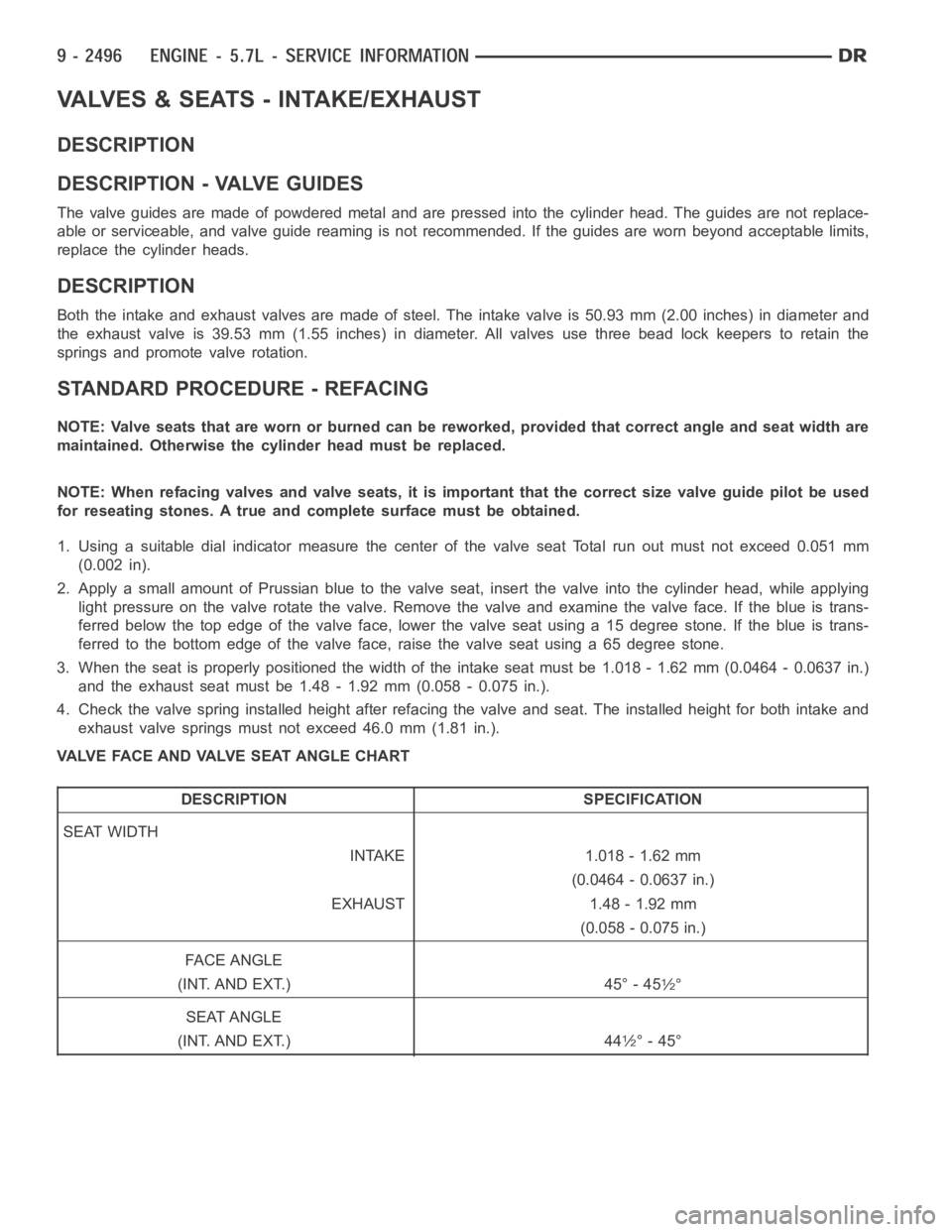
VALVE FACE AND VALVE SEAT ANGLE CHART
DESCRIPTION SPECIFICATION
SEAT WIDTH
INTAKE 1.018 - 1.62 mm
(0.0464 - 0.0637 in.)
EXHAUST 1.48 - 1.92 mm
(0.058 - 0.075 in.)
FA C E A N G L E
(INT. AND EXT.) 45° - 45
1⁄2°
SEAT ANGLE
(INT. AND EXT.) 44
1⁄2° - 45°
Page 1806 of 5267
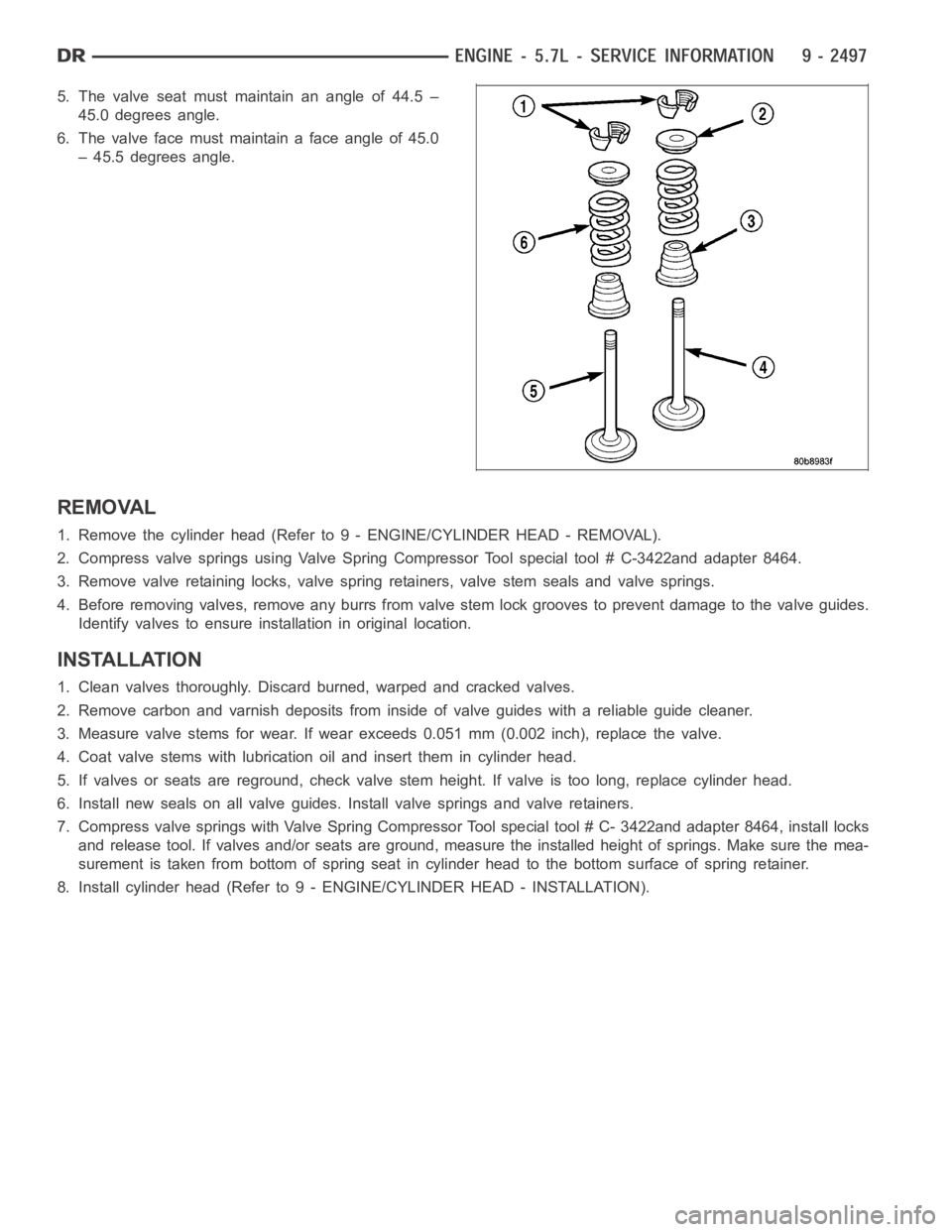
5. The valve seat must maintain an angle of 44.5 –
45.0 degrees angle.
6. Thevalvefacemustmaintainafaceangleof45.0
– 45.5 degrees angle.
REMOVAL
1. Remove the cylinder head (Refer to 9 - ENGINE/CYLINDER HEAD - REMOVAL).
2. Compress valve springs using Valve Spring Compressor Tool special tool# C-3422and adapter 8464.
3. Remove valve retaining locks, valve spring retainers, valve stem sealsand valve springs.
4. Before removing valves, remove any burrs from valve stem lock grooves toprevent damage to the valve guides.
Identify valves to ensure installation in original location.
INSTALLATION
1. Clean valves thoroughly. Discard burned, warped and cracked valves.
2. Remove carbon and varnish deposits from inside of valve guides with a reliable guide cleaner.
3. Measure valve stems for wear. If wear exceeds 0.051 mm (0.002 inch), replace the valve.
4. Coat valve stems with lubrication oil and insert them in cylinder head.
5. If valves or seats are reground, check valve stem height. If valve is too long, replace cylinder head.
6. Install new seals on all valve guides. Install valve springs and valve retainers.
7. Compress valve springs with Valve Spring Compressor Tool special tool #C- 3422and adapter 8464, install locks
and release tool. If valves and/or seats are ground, measure the installedheight of springs. Make sure the mea-
surement is taken from bottom of spring seat in cylinder head to the bottom surface of spring retainer.
8. Install cylinder head (Refer to 9 - ENGINE/CYLINDER HEAD - INSTALLATION).
Page 2006 of 5267
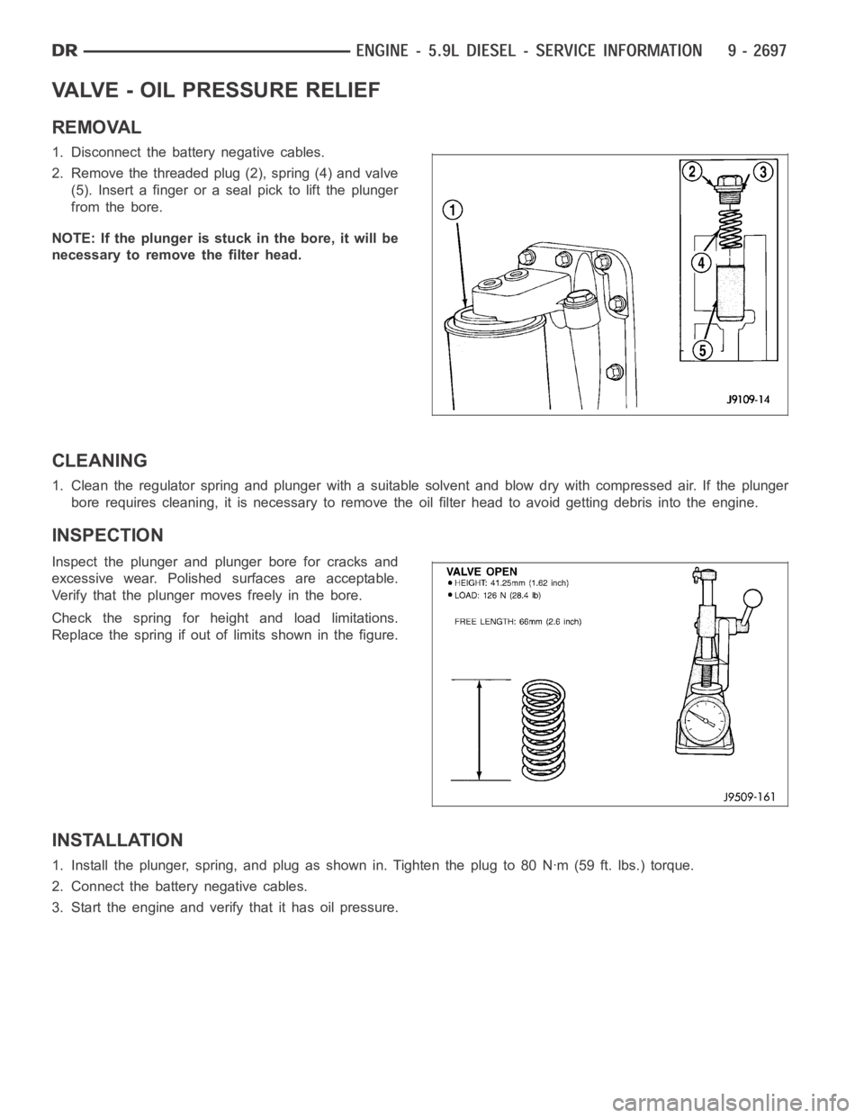
VALVE - OIL PRESSURE RELIEF
REMOVAL
1. Disconnect the battery negative cables.
2. Remove the threaded plug (2), spring (4) and valve
(5). Insert a finger or a seal pick to lift the plunger
from the bore.
NOTE: If the plunger is stuck in the bore, it will be
necessary to remove the filter head.
CLEANING
1. Clean the regulator spring and plunger with a suitable solvent and blow dry with compressed air. If the plunger
bore requires cleaning, it is necessaryto remove the oil filter head to avoid getting debris into the engine.
INSPECTION
Inspect the plunger and plunger bore for cracks and
excessive wear. Polished surfaces are acceptable.
Verify that the plunger moves freely in the bore.
Check the spring for height and load limitations.
Replace the spring if out of limits shown in the figure.
INSTALLATION
1. Install the plunger, spring, and plug as shown in. Tighten the plug to 80 Nꞏm (59 ft. lbs.) torque.
2. Connect the battery negative cables.
3. Start the engine and verify that it has oil pressure.
Page 2041 of 5267
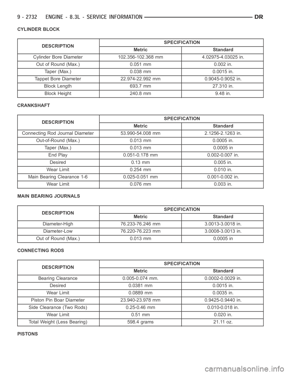
CYLINDER BLOCK
DESCRIPTIONSPECIFICATION
Metric Standard
Cylinder Bore Diameter 102.356-102.368 mm 4.02975-4.03025 in.
Out of Round (Max.) 0.051 mm 0.002 in.
Taper (Max.) 0.038 mm 0.0015 in.
Tappet Bore Diameter 22.974-22.992 mm 0.9045-0.9052 in.
Block Length 693.7 mm 27.310 in.
Block Height 240.8 mm 9.48 in.
CRANKSHAFT
DESCRIPTIONSPECIFICATION
Metric Standard
Connecting Rod Journal Diameter 53.990-54.008 mm 2.1256-2.1263 in.
Out-of-Round (Max.) 0.013 mm 0.0005 in.
Taper (Max.) 0.013 mm 0.0005 in
End Play 0.051-0.178 mm 0.002-0.007 in.
Desired 0.13 mm 0.005 in.
Wear Limit 0.254 mm 0.010 in.
Main Bearing Clearance 1-6 0.025-0.051 mm 0.001-0.002 in.
Wear Limit 0.076 mm 0.003 in.
MAIN BEARING JOURNALS
DESCRIPTIONSPECIFICATION
Metric Standard
Diameter-High 76.233-76.246 mm 3.0013-3.0018 in.
Diameter-Low 76.220-76.223 mm 3.0008-3.0013 in.
Out of Round (Max.) 0.013 mm 0.0005 in
CONNECTING RODS
DESCRIPTIONSPECIFICATION
Metric Standard
Bearing Clearance 0.005-0.074 mm. 0.0002-0.0029 in.
Desired 0.0381mm 0.0015in.
Wear Limit 0.0889 mm 0.0035 in.
Piston Pin Boar Diameter 23.940-23.978 mm 0.9425-0.9440 in.
Side Clearance (Two Rods) 0.25-0.46 mm 0.010-0.018 in.
Wear Limit 0.51 mm 0.020 in.
Total Weight (Less Bearing) 598.4 grams 21.11 oz.
PISTONS