radio DODGE RAM SRT-10 2006 Service Repair Manual
[x] Cancel search | Manufacturer: DODGE, Model Year: 2006, Model line: RAM SRT-10, Model: DODGE RAM SRT-10 2006Pages: 5267, PDF Size: 68.7 MB
Page 1601 of 5267
5. Disconnect vapor purge hose, brake booster hose, speed control servo hose, positive crankcase ventilation
(PCV) hose.
6. Disconnect generator electrical connections.
7. Disconnect air conditioning compressor electrical connections.
8. Disconnect left and right radio suppressor straps.
9. Disconnect and remove ignition coil towers.
10. Remove top oil dipstick tube retaining bolt and ground strap.
11. Bleed fuel system (Refer to 14 - FUEL SYSTEM/FUEL DELIVERY - STANDARD PROCEDURE).
12. Remove fuel rail.
13. Remove throttle body assembly and mounting bracket.
14. Drain cooling system below coolant temperature level (Refer to 7 - COOLING - STANDARD PROCEDURE).
15. Remove the heater hoses from the engine front cover and the heater core.
16. Unclip and remove heater hoses and tubes from intake manifold.
17. Remove coolant temperature sensor (Refer to 7 - COOLING/ENGINE/ENGINE COOLANT TEMP SENSOR -
REMOVAL).
18. Remove intake manifold retaining fasteners in reverse order of tightening sequence.
19. Remove intake manifold.
INSTALLATION
1. Install intake manifold gaskets.
2. Install intake manifold.
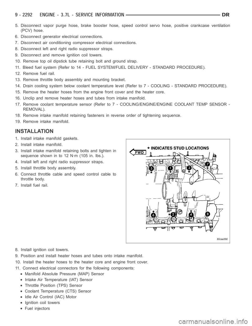
3. Install intake manifold retaining bolts and tighten in
sequence shown in to 12 Nꞏm (105 in. lbs.).
4. Install left and right radio suppressor straps.
5. Install throttle body assembly.
6. Connect throttle cable and speed control cable to
throttle body.
7. Install fuel rail.
8. Install ignition coil towers.
9. Position and install heater hoses and tubes onto intake manifold.
10. Install the heater hoses to the heater core and engine front cover.
11. Connect electrical connectors for the following components:
Manifold Absolute Pressure (MAP) Sensor
Intake Air Temperature (IAT) Sensor
Throttle Position (TPS) Sensor
Coolant Temperature (CTS) Sensor
Idle Air Control (IAC) Motor
Ignition coil towers
Fuel injectors
Page 1732 of 5267
MANIFOLD - INTAKE
DESCRIPTION
The intake manifold is made of a composite material and features long runners which maximizes low end torque.
The intake manifold uses single plane sealing which consist of eight individual press in place port gaskets to prevent
leaks. Eight studs and two bolts are used to fasten the intake to the head.
DIAGNOSIS AND TESTING - INTAKE MANIFOLD LEAKAGE
An intake manifold air leak is characterized by lower than normal manifoldvacuum. Also, one or more cylinders may
not be functioning.
WARNING: USE EXTREME CAUTION WHEN THE ENGINE IS OPERATING. DO NOT STAND IN ADIRECT LINE
WITH THE FAN. DO NOT PUT YOUR HANDS NEAR THE PULLEYS, BELTS OR THE FAN. DO NOT WEAR
LOOSE CLOTHING.
1. Start the engine.
2. Spray a small stream of water at the suspected leak area.
3. If a change in RPM is observed the area of the suspected leak has been found.
4. Repair as required.
REMOVAL
1. Disconnect negative cable from battery.
2. Remove resonator assembly and air inlet hose.
3. Disconnect throttle and speed control cables.
4. Disconnect electrical connectors for the following components:
Manifold Absolute Pressure (MAP) Sensor
Intake Air Temperature (IAT) Sensor
Throttle Position (TPS) Sensor
Coolant Temperature (CTS) Sensor
Idle Air Control (IAC) Motor
5. Disconnect brake booster hose and positive crankcase ventilation (PCV)hose.
6. Disconnect generator electrical connections.
7. Disconnect air conditioning compressor electrical connections.
8. Disconnect left and right radio suppressor straps.
9. Disconnect and remove ignition coil towers (Refer to 8 - ELECTRICAL/IGNITION CONTROL/IGNITION COIL -
REMOVAL).
10. Remove top oil dipstick tube retaining bolt and ground strap.
11. Bleed fuel system (Refer to 14 - FUEL SYSTEM/FUEL DELIVERY - STANDARD PROCEDURE).
12. Remove fuel rail (Refer to 14 - FUEL SYSTEM/FUEL DELIVERY/FUEL RAIL - REMOVAL).
13. Remove throttle body assembly and mounting bracket.
14. Drain cooling system below coolant temperature level (Refer to 7 - COOLING - STANDARD PROCEDURE).
Page 1734 of 5267
INSTALLATION
1. Install intake manifold gaskets.
2. Position intake manifold.
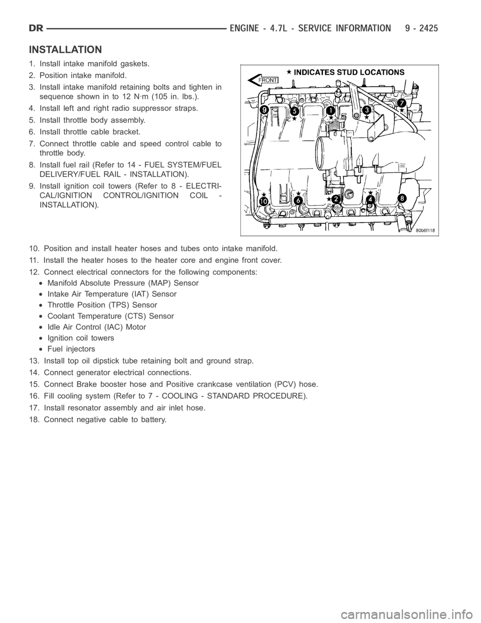
3. Install intake manifold retaining bolts and tighten in
sequence shown in to 12 Nꞏm (105 in. lbs.).
4. Install left and right radio suppressor straps.
5. Install throttle body assembly.
6. Install throttle cable bracket.
7. Connect throttle cable and speed control cable to
throttle body.
8. Install fuel rail (Refer to 14 - FUEL SYSTEM/FUEL
DELIVERY/FUEL RAIL - INSTALLATION).
9. Install ignition coil towers (Refer to 8 - ELECTRI-
CAL/IGNITION CONTROL/IGNITION COIL -
INSTALLATION).
10. Position and install heater hoses and tubes onto intake manifold.
11. Install the heater hoses to the heater core and engine front cover.
12. Connect electrical connectors for the following components:
Manifold Absolute Pressure (MAP) Sensor
Intake Air Temperature (IAT) Sensor
Throttle Position (TPS) Sensor
Coolant Temperature (CTS) Sensor
Idle Air Control (IAC) Motor
Ignition coil towers
Fuel injectors
13. Install top oil dipstick tube retaining bolt and ground strap.
14. Connect generator electrical connections.
15. Connect Brake booster hose and Positive crankcase ventilation (PCV) hose.
16. Fill cooling system (Refer to 7 - COOLING - STANDARD PROCEDURE).
17. Install resonator assembly and air inlet hose.
18. Connect negative cable to battery.
Page 4432 of 5267
FRONT FENDER
REMOVAL
1. Remove the radio antenna (Refer to 8 - ELECTRI-
CAL/AUDIO/ANTENNA BODY & CABLE -
REMOVAL).
2. Remove the battery tray (depending on fender
beingserviced)(Referto8-ELECTRICAL/BAT-
TERY SYSTEM/TRAY - REMOVAL).
3. Remove the cowl grille (Refer to 23 - BODY/EXTE-
RIOR/COWL GRILLE - REMOVAL).
4. Remove the headlamp unit (Refer to 8 - ELECTRI-
CAL/LAMPS/LIGHTING - EXTERIOR/HEADLAMP
UNIT - REMOVAL).
5. Remove the wheelhouse splash shield (Refer to 23
- BODY/EXTERIOR/FRONT WHEELHOUSE
SPLASH SHIELD - REMOVAL).
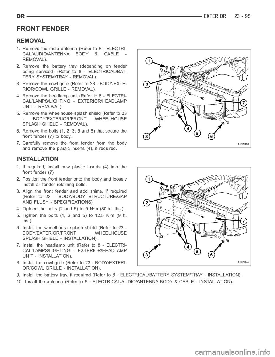
6. Remove the bolts (1, 2, 3, 5 and 6) that secure the
front fender (7) to body.
7. Carefully remove the front fender from the body
and remove the plastic inserts (4), if required.
INSTALLATION
1. If required, install new plastic inserts (4) into the
front fender (7).
2. Position the front fender onto the body and loosely
install all fender retaining bolts.
3. Align the front fender and add shims, if required
(Refer to 23 - BODY/BODY STRUCTURE/GAP
AND FLUSH - SPECIFICATIONS).
4. Tighten the bolts (2 and 6) to 9 Nꞏm (80 in. lbs.).
5. Tighten the bolts (1, 3 and 5) to 12.5 Nꞏm (9 ft.
lbs.).
6. Install the wheelhouse splash shield (Refer to 23 -
BODY/EXTERIOR/FRONT WHEELHOUSE
SPLASH SHIELD - INSTALLATION).
7. Install the headlamp unit (Refer to 8 - ELECTRI-
CAL/LAMPS/LIGHTING - EXTERIOR/HEADLAMP
UNIT - INSTALLATION).
8. Install the cowl grille (Refer to 23 - BODY/EXTERI-
OR/COWL GRILLE - INSTALLATION).
9. Install the battery tray, if required (Refer to 8 - ELECTRICAL/BATTERY SYSTEM/TRAY - INSTALLATION).
10. Install the antenna (Refer to 8 - ELECTRICAL/AUDIO/ANTENNA BODY & CABLE - INSTALLATION).
Page 4490 of 5267
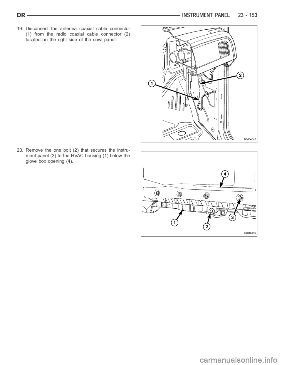
19. Disconnect the antenna coaxial cable connector
(1) from the radio coaxial cable connector (2)
located on the right side of the cowl panel.
20. Remove the one bolt (2) that secures the instru-
ment panel (3) to the HVAC housing (1) below the
glove box opening (4).
Page 4494 of 5267
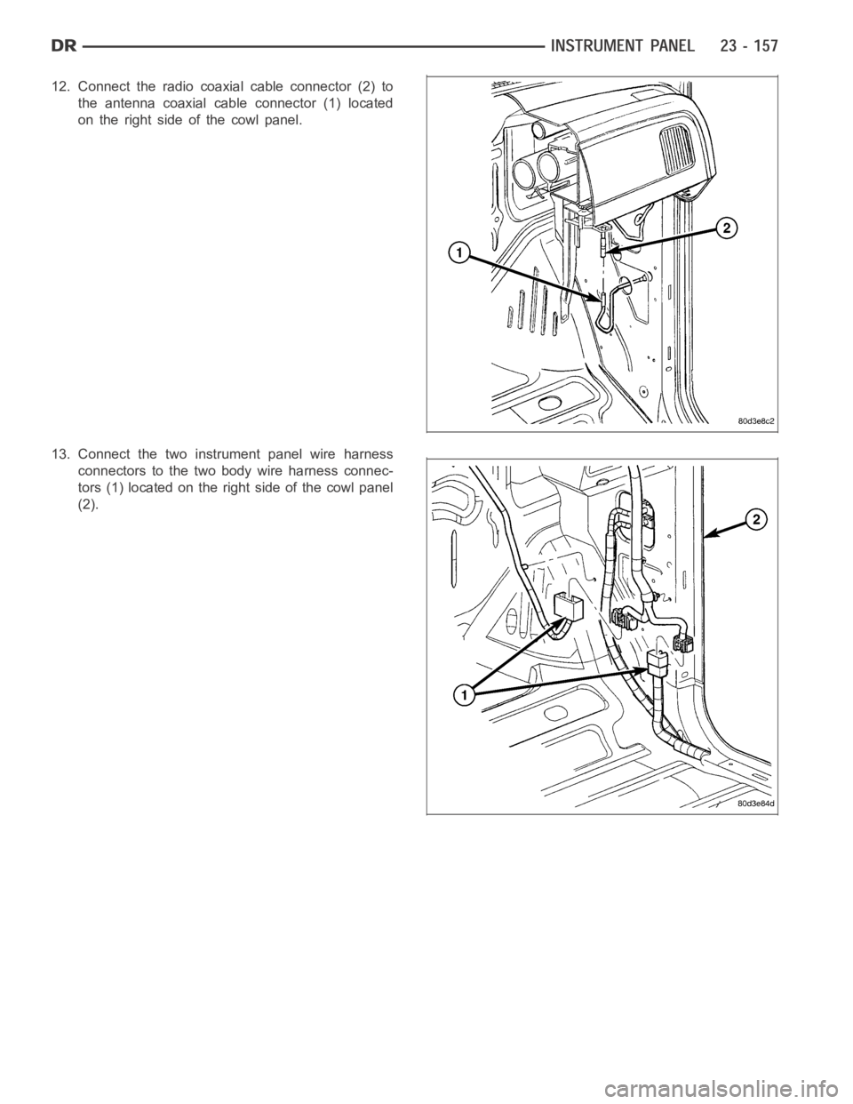
12. Connect the radio coaxial cable connector (2) to
the antenna coaxial cable connector (1) located
on the right side of the cowl panel.
13. Connect the two instrument panel wire harness
connectors to the two body wire harness connec-
tors (1) located on the right side of the cowl panel
(2).
Page 4843 of 5267
B1016–REAR DEFROST SWITCH REQUEST
INPUT CIRCUIT LOW (SINGLE-ZONE)....... 105
B1031–EVAPORATOR TEMPERATURE
SENSOR CIRCUIT LOW.................... 107
B1032–EVAPORATOR TEMPERATURE
SENSOR CIRCUIT HIGH.................... 110
B1040–PANEL MODE DOOR 1 CONTROL
CIRCUIT/PERFORMANCE. . ................ 114
B1041–PANEL MODE DOOR 1 CONTROL
CIRCUIT LOW (DUAL-ZONE)................ 115
B1041–PANEL MODE DOOR 1 CONTROL
CIRCUIT LOW (SINGLE-ZONE).............. 119
B1042–PANEL MODE DOOR 1 CONTROL
CIRCUIT HIGH (DUAL-ZONE)............... 123
B1042–PANEL MODE DOOR 1 CONTROL
CIRCUIT HIGH (SINGLE-ZONE)............. 126
B1043–PANEL MODE DOOR 1 CONTROL
CIRCUIT OPEN (DUAL-ZONE).............. 129
B1043–PANEL MODE DOOR 1 CONTROL
CIRCUIT OPEN (SINGLE-ZONE)............ 132
B 1 0 4 4 – PA N E L M O D E D O O R 1 T R AV E L
RANGE TOO SMALL....................... 135
B 1 0 4 5 – PA N E L M O D E D O O R 1 T R AV E L
RANGE TOO LARGE....................... 137
B1046–FLOOR/DEFROST MODE DOOR
CONTROL CIRCUIT/PERFORMANCE........ 139
B1047–FLOOR/DEFROST MODE DOOR
CONTROL CIRCUIT LOW (DUAL-ZONE)..... 140
B1047–FLOOR/DEFROST MODE DOOR
CONTROL CIRCUIT LOW (SINGLE-ZONE)... 144
B1048–FLOOR/DEFROST MODE DOOR
CONTROL CIRCUIT HIGH (DUAL-ZONE)..... 148
B1048–FLOOR/DEFROST MODE DOOR
CONTROL CIRCUIT HIGH (SINGLE-ZONE)... 151
B1049–FLOOR/DEFROST MODE DOOR
CONTROL CIRCUIT OPEN (DUAL-ZONE).... 154
B1049–FLOOR/DEFROST MODE DOOR
CONTROL CIRCUIT OPEN (SINGLE-
ZONE).................................... 157
B1050–BLEND DOOR TRAVEL RANGE TOO
SMALL (SINGLE-ZONE).................... 160
B1051–BLEND DOOR TRAVEL RANGE TOO
LARGE (SINGLE-ZONE).................... 162
B1058–RECIRCULATION DOOR CONTROL
CIRCUIT/PERFORMANCE.................. 164
B1059–RECIRCULATION DOOR CONTROL
CIRCUIT LOW (DUAL-ZONE)................ 165
B1059–RECIRCULATION DOOR CONTROL
CIRCUIT LOW (SINGLE-ZONE).............. 169
B1060–CLIMATE CONTROL MOTOR(S)
COMMON 1 CONTROL CIRCUIT HIGH
(DUAL-ZONE).............................. 173B1060–CLIMATE CONTROL MOTOR(S)
COMMON 1 CONTROL CIRCUIT HIGH
(SINGLE-ZONE)............................ 176
B1061–CLIMATE CONTROL MOTOR(S)
COMMON 1 CONTROL CIRCUIT OPEN
(DUAL-ZONE).............................. 179
B1061–CLIMATE CONTROL MOTOR(S)
COMMON 1 CONTROL CIRCUIT OPEN
(SINGLE-ZONE)............................ 186
B1079–CLIMATE CONTROL COOL DOWN
TEST EXCESSIVE TIME (SINGLE-ZONE). . . . 192
B2214–(HVAC) CLIMATE CONTROL
INTERNAL................................. 194
U0019–CAN B BUS ........................ 195
U0141–LOST COMMUNICATION WITH
FRONT CONTROL MODULE................ 197
U0151–LOST COMMUNICATION WITH
OCCUPANT RESTRAINT CONTROLLER
(ORC)..................................... 198
U0154–LOST COMMUNICATION WITH
OCCUPANT CLASSIFICATION MODULE
..... 198
U0155–LOST COMMUNICATION WITH
CLUSTER/CCN............................ 198
U0156–LOST COMMUNICATION WITH EOM . 198
U0168–LOST COMMUNICATION WITH
VEHICLE SECURITY CONTROL MODULE
(SKREEM/WCM)........................... 198
U0169–LOST COMMUNICATION WITH
SUNROOF CONTROL MODULE............. 199
U0184–LOST COMMUNICATION WITH
RADIO.................................... 199
U0186–LOST COMMUNICATION WITH
AUDIO AMPLIFIER......................... 199
U0195–LOST COMMUNICATION WITH
SDARS.................................... 199
U0196–LOST COMMUNICATION WITH
VEHICLE ENTERTAINMENT CONTROL
MODULE.................................. 199
U0197–LOST COMMUNICATION WITH
HANDS FREE PHONE MODULE............ 200
DTC SET DURING ROUTINE - TEST NOT
PASSED.................................. 200
BLOWERS NOT ON HIGH - TEST NOT RUN . 200
REFRIGERANT TEMPERATURE SENSOR
ERROR................................... 200
*BLOWER MOTOR INOPERATIVE ........... 201
*HVAC SYSTEM TEST ..................... 205
Page 5040 of 5267
When Monitored:
With the ignition on.
Set Condition:
If the A/C Heater Control looses communication with the Vehicle Security Control Module (SKREEM/WCM).
(Refer to 8 - ELECTRICAL/ELECTRONIC CONTROL MODULES - DIAGNOSIS AND TESTING)for the diagnostic
test procedure.
U0169–LOST COMMUNICATION WITH SUNROOF CONTROL MODULE
For a complete wiring diagramRefer to Section 8W.
When Monitored:
With the ignition on.
Set Condition:
If the A/C Heater Control looses communication with the Sunroof Control Module (SCM).
(Refer to 8 - ELECTRICAL/ELECTRONIC CONTROL MODULES - DIAGNOSIS AND TESTING)for the diagnostic
test procedure.
U0184–LOST COMMUNICATION WITH RADIO
For a complete wiring diagramRefer to Section 8W.
When Monitored:
With the ignition on.
Set Condition:
If the A/C Heater Control looses communication with the Radio.
(Refer to 8 - ELECTRICAL/ELECTRONIC CONTROL MODULES - DIAGNOSIS AND TESTING)for the diagnostic
test procedure.
U0186–LOST COMMUNICATION WITH AUDIO AMPLIFIER
For a complete wiring diagramRefer to Section 8W.
When Monitored:
With the ignition on.
Set Condition:
If the A/C Heater Control looses communication with the Amplifier (AMP).
(Refer to 8 - ELECTRICAL/ELECTRONIC CONTROL MODULES - DIAGNOSIS AND TESTING)for the diagnostic
test procedure.
U0195–LOST COMMUNICATION WITH SDARS
For a complete wiring diagramRefer to Section 8W.
When Monitored:
With the ignition on.
Set Condition:
If the A/C Heater Control looses communication with the Satellite Audio Receiver (SDARS).
(Refer to 8 - ELECTRICAL/ELECTRONIC CONTROL MODULES - DIAGNOSIS AND TESTING)for the diagnostic
test procedure.
U0196–LOST COMMUNICATION WITHVEHICLE ENTERTAINMENT CONTROL
MODULE
For a complete wiring diagramRefer to Section 8W.
Page 5095 of 5267
DUCT-DEFROSTER
REMOVAL
WARNING: On vehicles equipped with airbags, disable the airbag system before attempting any steering
wheel, steering column, or instrument panel component diagnosis or service. Disconnect and isolate the
battery negative (ground) cable, then wait two minutes for the airbag system capacitor to discharge before
performing further diagnosis or service. This is the only sure way to disable the airbag system. Failure to
take the proper precautions could result in accidental airbag deploymentand possible personal injury or
death.
NOTE: Take the proper precautions to protect the instrument panel from cosmetic damage.
1. Remove the instrument panel and place it on a workbench (Refer to 23 - BODY/INSTRUMENT PANEL/INSTRU-
MENT PANEL ASSEMBLY - REMOVAL).
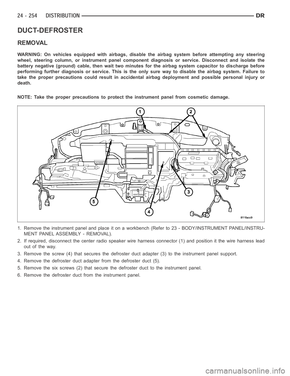
2. If required, disconnect the center radio speaker wire harness connector (1) and position it the wire harness lead
out of the way.
3. Remove the screw (4) that secures the defroster duct adapter (3) to the instrument panel support.
4. Remove the defroster duct adapter from the defroster duct (5).
5. Remove the six screws (2) that secure the defroster duct to the instrument panel.
6. Remove the defroster duct from the instrument panel.
Page 5096 of 5267
INSTALLATION
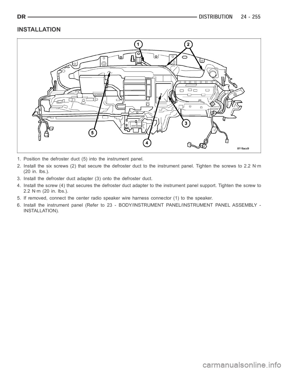
1. Position the defroster duct (5) into the instrument panel.
2. Install the six screws (2) that secure the defroster duct to the instrument panel. Tighten the screws to 2.2 Nꞏm
(20 in. lbs.).
3. Install the defroster duct adapter (3) onto the defroster duct.
4. Install the screw (4) that secures the defroster duct adapter to the instrument panel support. Tighten the screw to
2.2 Nꞏm (20 in. lbs.).
5. If removed, connect the center radiospeaker wire harness connector (1)to the speaker.
6. Install the instrument panel (Refer to 23 - BODY/INSTRUMENT PANEL/INSTRUMENT PANEL ASSEMBLY -
INSTALLATION).