check engine DODGE RAM SRT-10 2006 Service Repair Manual
[x] Cancel search | Manufacturer: DODGE, Model Year: 2006, Model line: RAM SRT-10, Model: DODGE RAM SRT-10 2006Pages: 5267, PDF Size: 68.7 MB
Page 1 of 5267
3.PCM
NOTE: Before continuing, check the PCM harness connector terminals for corrosion, damage, or terminal
push out. Repair as necessary.
Using the schematics as a guide, inspect the wire harness and connectors. Pay particular attention to all Power and
Ground circuits.
Were there any problems found?
Ye s>>
Repair as necessary.
Perform the POWERTRAIN VERIFICATION TEST. (Refer to 9 - ENGINE - STANDARD PROCEDURE)
No>>
Replace and program the Powertrain Control Module per Service Information.
Perform the POWERTRAIN VERIFICATION TEST. (Refer to 9 - ENGINE - STANDARD PROCEDURE)
Page 5 of 5267
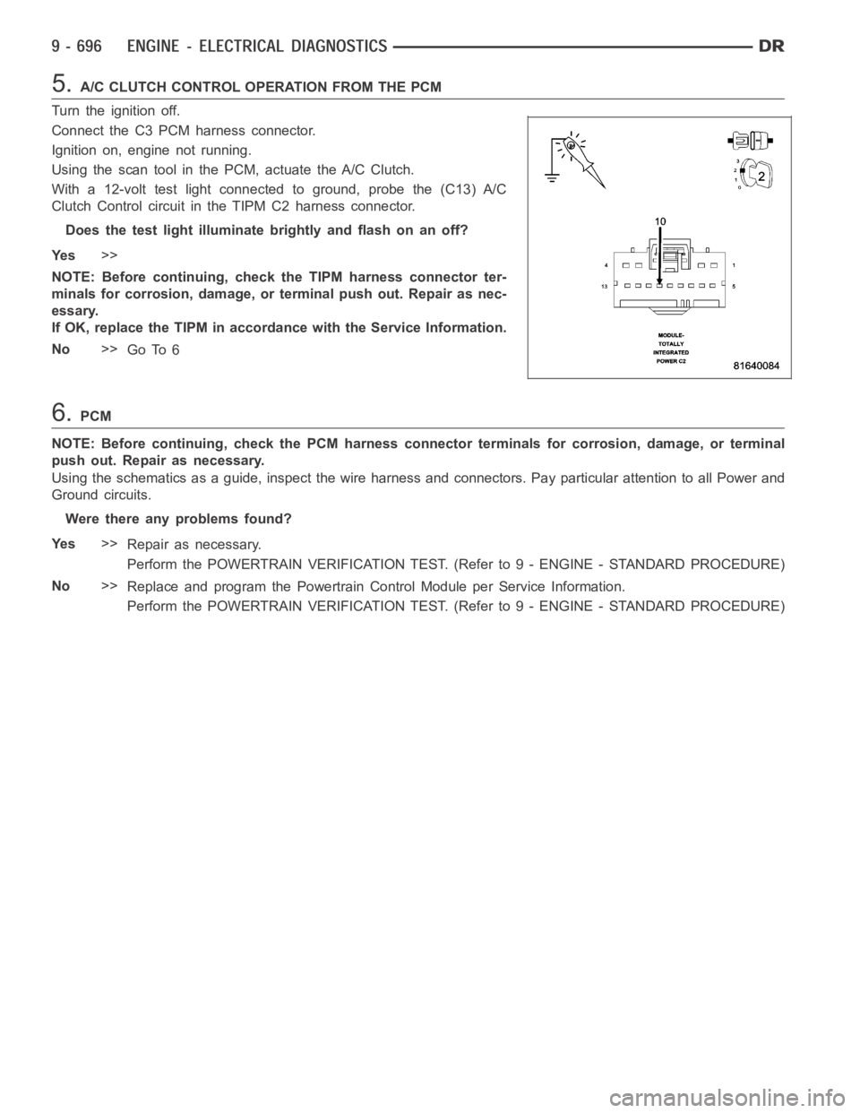
5.A/C CLUTCH CONTROL OPERATION FROM THE PCM
Turn the ignition off.
Connect the C3 PCM harness connector.
Ignition on, engine not running.
Using the scan tool in the PCM, actuate the A/C Clutch.
With a 12-volt test light connected to ground, probe the (C13) A/C
Clutch Control circuit in the TIPM C2 harness connector.
Does the test light illuminate brightly and flash on an off?
Ye s>>
NOTE: Before continuing, check the TIPM harness connector ter-
minals for corrosion, damage, or terminal push out. Repair as nec-
essary.
If OK, replace the TIPM in accordance with the Service Information.
No>>
Go To 6
6.PCM
NOTE: Before continuing, check the PCM harness connector terminals for corrosion, damage, or terminal
push out. Repair as necessary.
Using the schematics as a guide, inspect the wire harness and connectors. Pay particular attention to all Power and
Ground circuits.
Were there any problems found?
Ye s>>
Repair as necessary.
Perform the POWERTRAIN VERIFICATION TEST. (Refer to 9 - ENGINE - STANDARD PROCEDURE)
No>>
Replace and program the Powertrain Control Module per Service Information.
Perform the POWERTRAIN VERIFICATION TEST. (Refer to 9 - ENGINE - STANDARD PROCEDURE)
Page 7 of 5267
When Monitored:
Ignition on.
Set Condition:
When the PCM recognizes the Auxiliary 5-volt Supply circuit voltage is toolow. One Trip Fault. ETC light is
flashing.
Possible Causes
(F856) AUXILIARY 5-VOLT SUPPLY SHORTED TO GROUND
SENSOR SHORTED TO GROUND
CAM POSITION SENSOR
PCM
Always perform the Pre-Diagnostic Troubleshooting procedure before proceeding. (Refer to 9 - ENGINE -
DIAGNOSIS AND TESTING).
Diagnostic Test
1.ACTIVE DTC
Ignition on, engine not running.
With a scan tool, read DTCs.
NOTE: Improperly installed aftermarket accessories can cause this DTC toset. Check for wiring added by
customer.
Is the DTC active at this time?
Ye s>>
Go To 2
No>>
Refer to the INTERMITTENT CONDITION Diagnostic Procedure.
Perform the POWERTRAIN VERIFICATION TEST. (Refer to 9 - ENGINE - STANDARD PROCEDURE)
2.(F856) AUXILIARY 5-VOLT SUPPLY SHORTED TO GROUND
Turn the ignition off.
Disconnect the C1 PCM harness connector.
Disconnect all the Sensors that share the (F856) Auxiliary 5-volt Supply
circuit.
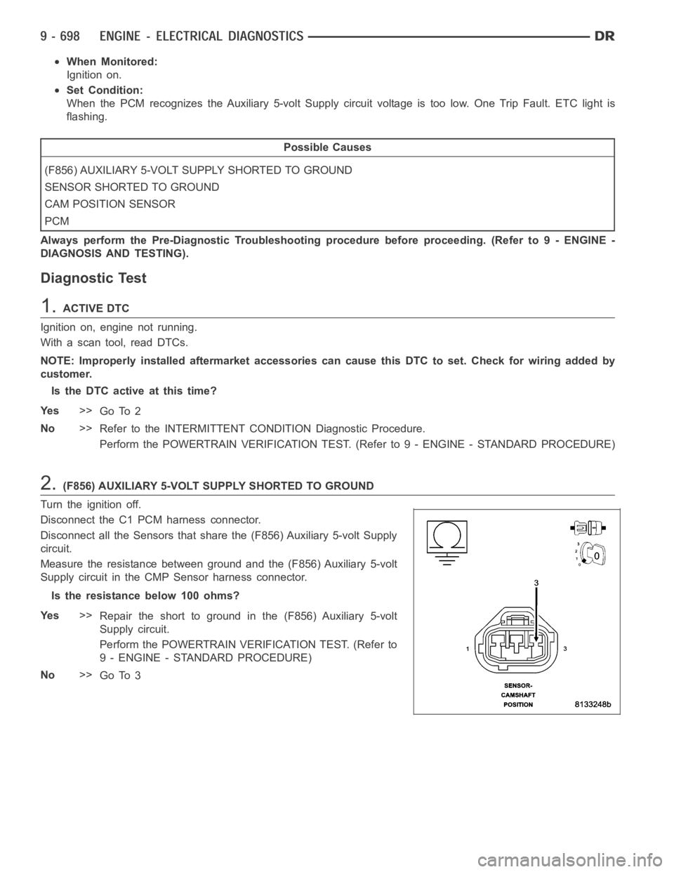
Measure the resistance between ground and the (F856) Auxiliary 5-volt
Supply circuit in the CMP Sensor harness connector.
Istheresistancebelow100ohms?
Ye s>>
Repair the short to ground in the (F856) Auxiliary 5-volt
Supply circuit.
Perform the POWERTRAIN VERIFICATION TEST. (Refer to
9 - ENGINE - STANDARD PROCEDURE)
No>>
Go To 3
Page 8 of 5267
3.CMP SENSOR
Turn the ignition off.
Reconnect all the previously disconnected Sensors except for the CMP
Sensor harness connector.
Ignition on, engine not running.
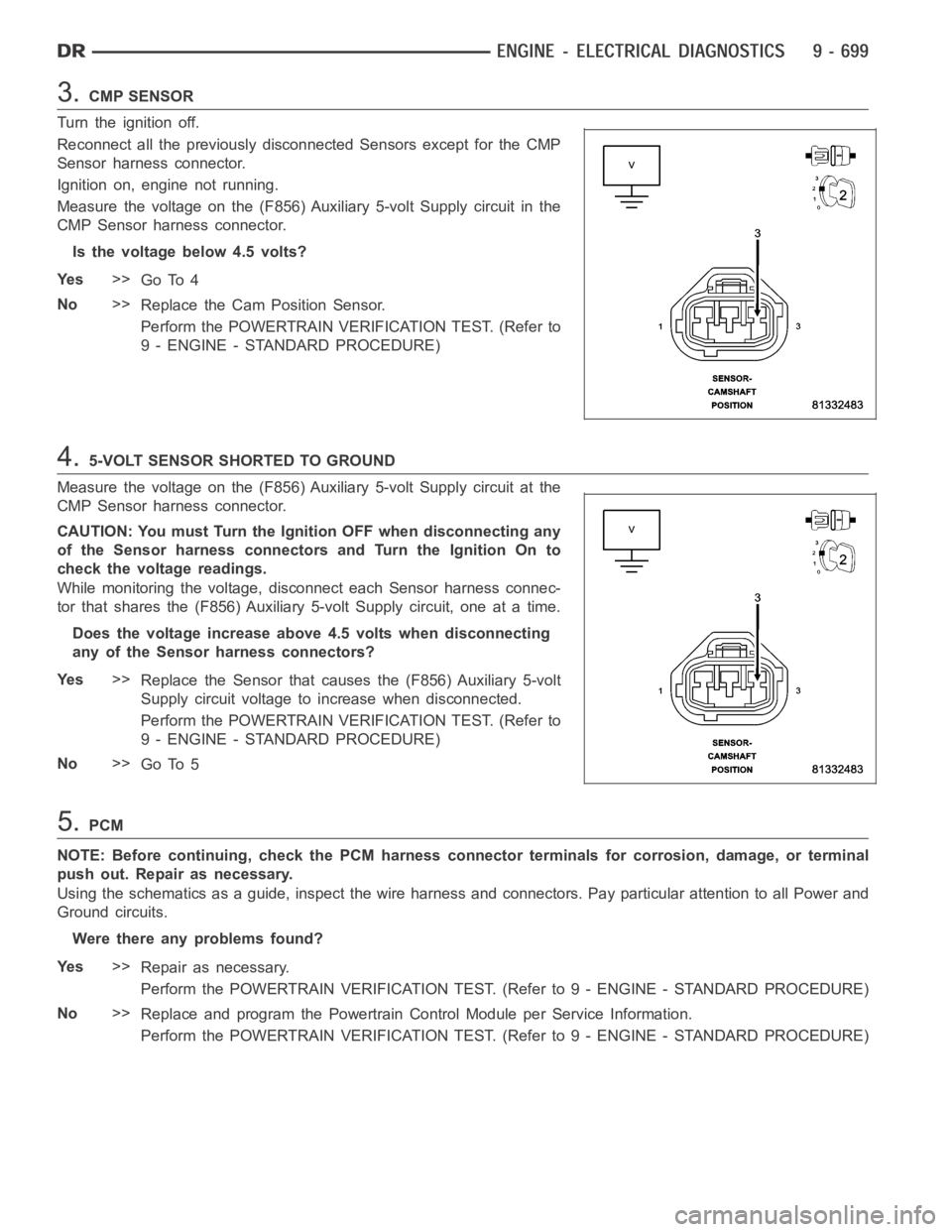
Measure the voltage on the (F856) Auxiliary 5-volt Supply circuit in the
CMP Sensor harness connector.
Is the voltage below 4.5 volts?
Ye s>>
Go To 4
No>>
Replace the Cam Position Sensor.
Perform the POWERTRAIN VERIFICATION TEST. (Refer to
9 - ENGINE - STANDARD PROCEDURE)
4.5-VOLT SENSOR SHORTED TO GROUND
Measure the voltage on the (F856) Auxiliary 5-volt Supply circuit at the
CMP Sensor harness connector.
CAUTION: You must Turn the Ignition OFF when disconnecting any
of the Sensor harness connectors and Turn the Ignition On to
check the voltage readings.
While monitoring the voltage, disconnect each Sensor harness connec-
tor that shares the (F856) Auxiliary 5-volt Supply circuit, one at a time.
Does the voltage increase above 4.5 volts when disconnecting
any of the Sensor harness connectors?
Ye s>>
Replace the Sensor that causes the (F856) Auxiliary 5-volt
Supply circuit voltage to increase when disconnected.
Perform the POWERTRAIN VERIFICATION TEST. (Refer to
9 - ENGINE - STANDARD PROCEDURE)
No>>
Go To 5
5.PCM
NOTE: Before continuing, check the PCM harness connector terminals for corrosion, damage, or terminal
push out. Repair as necessary.
Using the schematics as a guide, inspect the wire harness and connectors. Pay particular attention to all Power and
Ground circuits.
Were there any problems found?
Ye s>>
Repair as necessary.
Perform the POWERTRAIN VERIFICATION TEST. (Refer to 9 - ENGINE - STANDARD PROCEDURE)
No>>
Replace and program the Powertrain Control Module per Service Information.
Perform the POWERTRAIN VERIFICATION TEST. (Refer to 9 - ENGINE - STANDARD PROCEDURE)
Page 10 of 5267
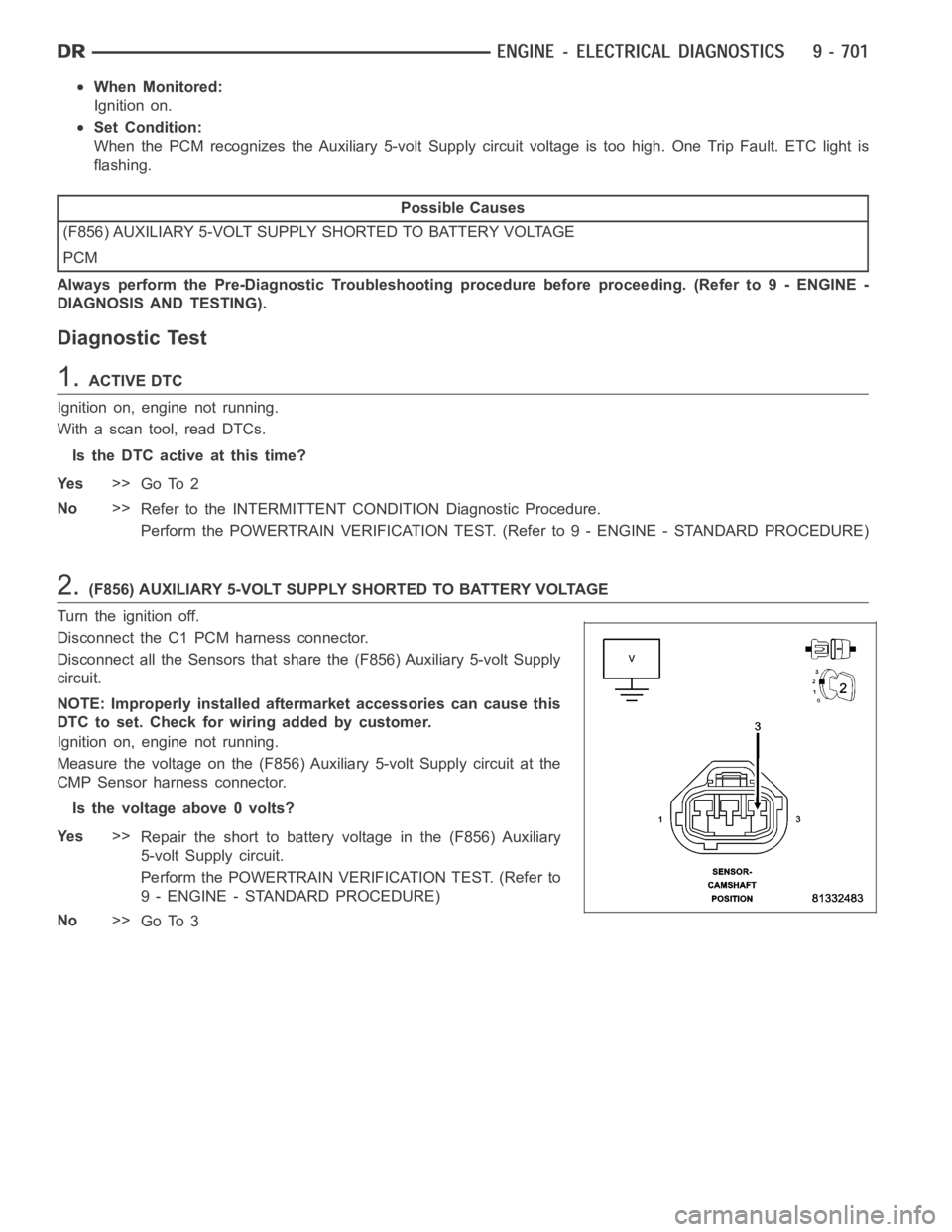
When Monitored:
Ignition on.
Set Condition:
When the PCM recognizes the Auxiliary 5-volt Supply circuit voltage is toohigh. One Trip Fault. ETC light is
flashing.
Possible Causes
(F856) AUXILIARY 5-VOLT SUPPLY SHORTED TO BATTERY VOLTAGE
PCM
Always perform the Pre-Diagnostic Troubleshooting procedure before proceeding. (Refer to 9 - ENGINE -
DIAGNOSIS AND TESTING).
Diagnostic Test
1.ACTIVE DTC
Ignition on, engine not running.
With a scan tool, read DTCs.
Is the DTC active at this time?
Ye s>>
Go To 2
No>>
Refer to the INTERMITTENT CONDITION Diagnostic Procedure.
Perform the POWERTRAIN VERIFICATION TEST. (Refer to 9 - ENGINE - STANDARD PROCEDURE)
2.(F856) AUXILIARY 5-VOLT SUPPLY SHORTED TO BATTERY VOLTAGE
Turn the ignition off.
Disconnect the C1 PCM harness connector.
Disconnect all the Sensors that share the (F856) Auxiliary 5-volt Supply
circuit.
NOTE: Improperly installed aftermarket accessories can cause this
DTC to set. Check for wiring added by customer.
Ignition on, engine not running.
Measure the voltage on the (F856) Auxiliary 5-volt Supply circuit at the
CMP Sensor harness connector.
Is the voltage above 0 volts?
Ye s>>
Repair the short to battery voltage in the (F856) Auxiliary
5-volt Supply circuit.
Perform the POWERTRAIN VERIFICATION TEST. (Refer to
9 - ENGINE - STANDARD PROCEDURE)
No>>
Go To 3
Page 11 of 5267
3.PCM
NOTE: Before continuing, check the PCM harness connector terminals for corrosion, damage, or terminal
push out. Repair as necessary.
Using the schematics as a guide, inspect the wire harness and connectors. Pay particular attention to all Power and
Ground circuits.
Were there any problems found?
Ye s>>
Repair as necessary.
Perform the POWERTRAIN VERIFICATION TEST. (Refer to 9 - ENGINE - STANDARD PROCEDURE)
No>>
Replace and program the Powertrain Control Module per Service Information.
Perform the POWERTRAIN VERIFICATION TEST. (Refer to 9 - ENGINE - STANDARD PROCEDURE)
Page 15 of 5267
6.PCM
NOTE: Before continuing, check the PCM harness connector terminals for corrosion, damage, or terminal
push out. Repair as necessary.
Using the schematics as a guide, inspect the wire harness and connectors. Pay particular attention to all Power and
Ground circuits.
Were there any problems found?
Ye s>>
Repair as necessary.
Perform the POWERTRAIN VERIFICATION TEST. (Refer to 9 - ENGINE - STANDARD PROCEDURE)
No>>
Replace and program the Powertrain Control Module per Service Information.
Perform the POWERTRAIN VERIFICATION TEST. (Refer to 9 - ENGINE - STANDARD PROCEDURE)
Page 20 of 5267
7.PCM
NOTE: Before continuing, check the PCM harness connector terminals for corrosion, damage, or terminal
push out. Repair as necessary.
Using the schematics as a guide, inspect the wire harness and connectors. Pay particular attention to all Power and
Ground circuits.
Were there any problems found?
Ye s>>
Repair as necessary.
Perform the POWERTRAIN VERIFICATION TEST. (Refer to 9 - ENGINE - STANDARD PROCEDURE)
No>>
Replace and program the Powertrain Control Module per Service Information.
Perform the POWERTRAIN VERIFICATION TEST. (Refer to 9 - ENGINE - STANDARD PROCEDURE)
Page 24 of 5267
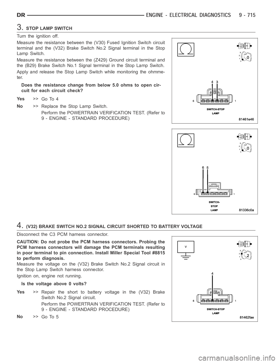
3.STOP LAMP SWITCH
Turn the ignition off.
Measure the resistance between the (V30) Fused Ignition Switch circuit
terminal and the (V32) Brake SwitchNo.2 Signal terminal in the Stop
Lamp Switch.
Measure the resistance between the (Z429) Ground circuit terminal and
the (B29) Brake Switch No.1 Signal terminal in the Stop Lamp Switch.
Apply and release the Stop Lamp Switch while monitoring the ohmme-
ter.
Does the resistance change from below 5.0 ohms to open cir-
cuit for each circuit check?
Ye s>>
Go To 4
No>>
Replace the Stop Lamp Switch.
Perform the POWERTRAIN VERIFICATION TEST. (Refer to
9 - ENGINE - STANDARD PROCEDURE)
4.(V32) BRAKE SWITCH NO.2 SIGNAL CIRCUIT SHORTED TO BATTERY VOLTAGE
Disconnect the C3 PCM harness connector.
CAUTION: Do not probe the PCM harness connectors. Probing the
PCM harness connectors will damage the PCM terminals resulting
in poor terminal to pin connection. Install Miller Special Tool #8815
to perform diagnosis.
Measure the voltage on the (V32) Brake Switch No.2 Signal circuit in
the Stop Lamp Switch harness connector.
Ignition on, engine not running.
Is the voltage above 0 volts?
Ye s>>
Repair the short to battery voltage in the (V32) Brake
Switch No.2 Signal circuit.
Perform the POWERTRAIN VERIFICATION TEST. (Refer to
9 - ENGINE - STANDARD PROCEDURE)
No>>
Go To 5
Page 26 of 5267
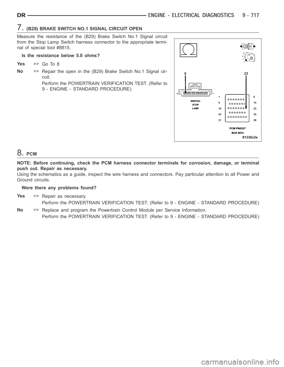
7.(B29) BRAKE SWITCH NO.1 SIGNAL CIRCUIT OPEN
Measure the resistance of the (B29) Brake Switch No.1 Signal circuit
from the Stop Lamp Switch harness connector to the appropriate termi-
nal of special tool #8815.
Is the resistance below 5.0 ohms?
Ye s>>
Go To 8
No>>
Repair the open in the (B29) Brake Switch No.1 Signal cir-
cuit.
Perform the POWERTRAIN VERIFICATION TEST. (Refer to
9 - ENGINE - STANDARD PROCEDURE)
8.PCM
NOTE: Before continuing, check the PCM harness connector terminals for corrosion, damage, or terminal
push out. Repair as necessary.
Using the schematics as a guide, inspect the wire harness and connectors. Pay particular attention to all Power and
Ground circuits.
Were there any problems found?
Ye s>>
Repair as necessary.
Perform the POWERTRAIN VERIFICATION TEST. (Refer to 9 - ENGINE - STANDARD PROCEDURE)
No>>
Replace and program the Powertrain Control Module per Service Information.
Perform the POWERTRAIN VERIFICATION TEST. (Refer to 9 - ENGINE - STANDARD PROCEDURE)