turn signal DODGE RAM SRT-10 2006 Service Repair Manual
[x] Cancel search | Manufacturer: DODGE, Model Year: 2006, Model line: RAM SRT-10, Model: DODGE RAM SRT-10 2006Pages: 5267, PDF Size: 68.7 MB
Page 23 of 5267
When Monitored:
Ignition on.
Set Condition:
When the PCM recognizes Brake Switch No.2 voltage is not equal to the applied value at the PCM when
Brake Switch No.1 is applied. This could be a normal condition. If this condition is seen repeatedly by the PCM
the fault is set. Cruise will not work for the rest of the key cycle.
Possible Causes
(V30)FUSEDIGNITIONSWITCHOUTPUTCIRCUIT
(V32) BRAKE SWITCH NO.2 SIGNAL CIRCUIT OPEN
(V32) BRAKE SWITCH NO.2 SIGNAL CIRCUIT SHORTED TO BATTERY VOLTAGE
(V32) BRAKE SWITCH NO.2 SIGNAL CIRCUIT SHORTED TO GROUND
(B29) BRAKE SWITCH NO.1 SIGNAL CIRCUIT OPEN
STOP LAMP SWITCH
PCM
Always perform the Pre-Diagnostic Troubleshooting procedure before proceeding. (Refer to 9 - ENGINE -
DIAGNOSIS AND TESTING).
Diagnostic Test
1.ACTIVE DTC
NOTE: Make sure the Stop Lamp Switch is adjusted properly before continuing.
NOTE: Make sure the Stop Lamp Switch is properly wired, such as (B29) Brake Switch No.1 and (L50) Brake
Lamp Switch Output are not switched at the harness connector.
Ignition on, engine not running.
With a scan tool, read DTCs.
Is the DTC active at this time?
Ye s>>
Go To 2
No>>
Refer to the INTERMITTENT CONDITION Diagnostic Procedure.
Perform the POWERTRAIN VERIFICATION TEST. (Refer to 9 - ENGINE - STANDARD PROCEDURE)
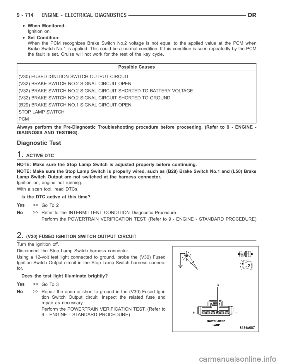
2.(V30) FUSED IGNITION SWITCH OUTPUT CIRCUIT
Turn the ignition off.
Disconnect the Stop Lamp Switch harness connector.
Using a 12-volt test light connected to ground, probe the (V30) Fused
Ignition Switch Output circuit in the Stop Lamp Switch harness connec-
tor.
Does the test light illuminate brightly?
Ye s>>
Go To 3
No>>
Repair the open or short to ground in the (V30) Fused Igni-
tion Switch Output circuit. Inspect the related fuse and
repair as necessary.
Perform the POWERTRAIN VERIFICATION TEST. (Refer to
9 - ENGINE - STANDARD PROCEDURE)
Page 24 of 5267
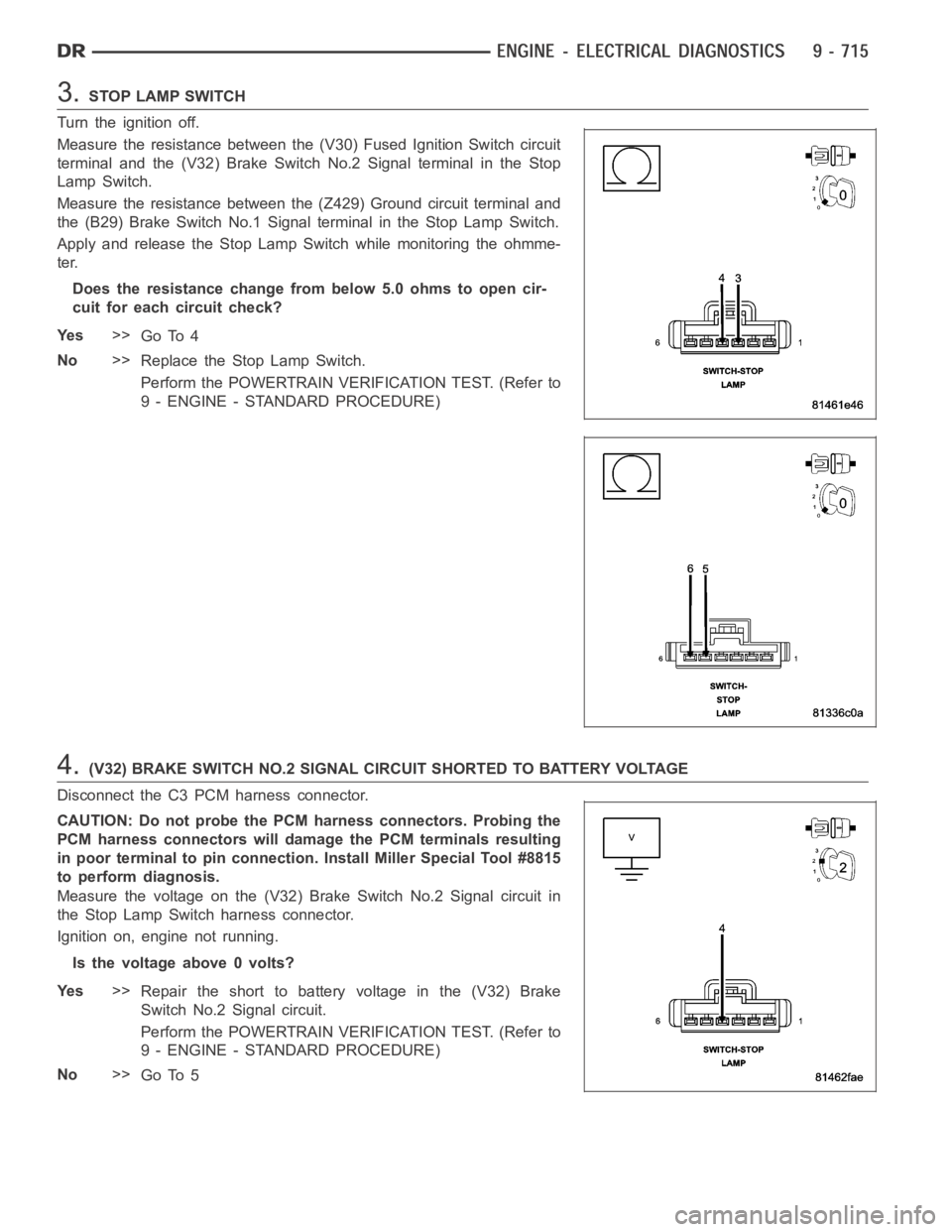
3.STOP LAMP SWITCH
Turn the ignition off.
Measure the resistance between the (V30) Fused Ignition Switch circuit
terminal and the (V32) Brake SwitchNo.2 Signal terminal in the Stop
Lamp Switch.
Measure the resistance between the (Z429) Ground circuit terminal and
the (B29) Brake Switch No.1 Signal terminal in the Stop Lamp Switch.
Apply and release the Stop Lamp Switch while monitoring the ohmme-
ter.
Does the resistance change from below 5.0 ohms to open cir-
cuit for each circuit check?
Ye s>>
Go To 4
No>>
Replace the Stop Lamp Switch.
Perform the POWERTRAIN VERIFICATION TEST. (Refer to
9 - ENGINE - STANDARD PROCEDURE)
4.(V32) BRAKE SWITCH NO.2 SIGNAL CIRCUIT SHORTED TO BATTERY VOLTAGE
Disconnect the C3 PCM harness connector.
CAUTION: Do not probe the PCM harness connectors. Probing the
PCM harness connectors will damage the PCM terminals resulting
in poor terminal to pin connection. Install Miller Special Tool #8815
to perform diagnosis.
Measure the voltage on the (V32) Brake Switch No.2 Signal circuit in
the Stop Lamp Switch harness connector.
Ignition on, engine not running.
Is the voltage above 0 volts?
Ye s>>
Repair the short to battery voltage in the (V32) Brake
Switch No.2 Signal circuit.
Perform the POWERTRAIN VERIFICATION TEST. (Refer to
9 - ENGINE - STANDARD PROCEDURE)
No>>
Go To 5
Page 25 of 5267
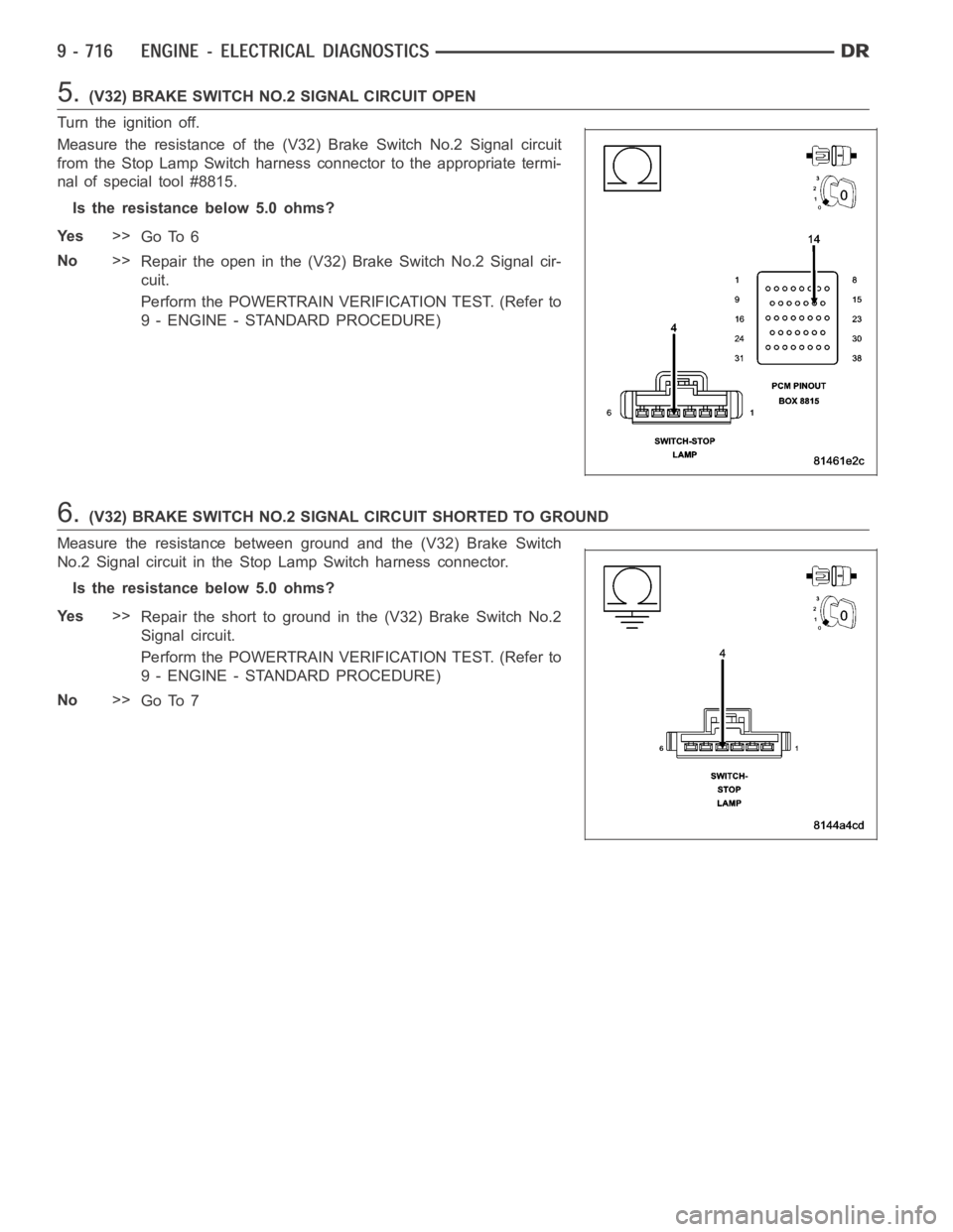
5.(V32) BRAKE SWITCH NO.2 SIGNAL CIRCUIT OPEN
Turn the ignition off.
Measure the resistance of the (V32) Brake Switch No.2 Signal circuit
from the Stop Lamp Switch harness connector to the appropriate termi-
nal of special tool #8815.
Is the resistance below 5.0 ohms?
Ye s>>
Go To 6
No>>
Repair the open in the (V32) Brake Switch No.2 Signal cir-
cuit.
Perform the POWERTRAIN VERIFICATION TEST. (Refer to
9 - ENGINE - STANDARD PROCEDURE)
6.(V32) BRAKE SWITCH NO.2 SIGNAL CIRCUIT SHORTED TO GROUND
Measure the resistance between ground and the (V32) Brake Switch
No.2 Signal circuit in the Stop Lamp Switch harness connector.
Is the resistance below 5.0 ohms?
Ye s>>
Repair the short to ground in the (V32) Brake Switch No.2
Signal circuit.
Perform the POWERTRAIN VERIFICATION TEST. (Refer to
9 - ENGINE - STANDARD PROCEDURE)
No>>
Go To 7
Page 29 of 5267
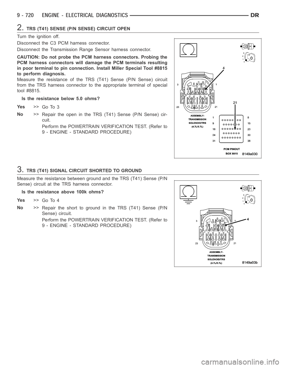
2.TRS (T41) SENSE (P/N SENSE) CIRCUIT OPEN
Turn the ignition off.
Disconnect the C3 PCM harness connector.
Disconnect the Transmission Range Sensor harness connector.
CAUTION: Do not probe the PCM harness connectors. Probing the
PCM harness connectors will damage the PCM terminals resulting
in poor terminal to pin connection. Install Miller Special Tool #8815
to perform diagnosis.
Measure the resistance of the TRS (T41) Sense (P/N Sense) circuit
from the TRS harness connector to the appropriate terminal of special
tool #8815.
Is the resistance below 5.0 ohms?
Ye s>>
Go To 3
No>>
Repair the open in the TRS (T41) Sense (P/N Sense) cir-
cuit.
Perform the POWERTRAIN VERIFICATION TEST. (Refer to
9 - ENGINE - STANDARD PROCEDURE)
3.TRS (T41) SIGNAL CIRCUIT SHORTED TO GROUND
Measure the resistance between ground and the TRS (T41) Sense (P/N
Sense) circuit at the TRS harness connector.
Is the resistance above 100k ohms?
Ye s>>
Go To 4
No>>
Repair the short to ground in the TRS (T41) Sense (P/N
Sense) circuit.
Perform the POWERTRAIN VERIFICATION TEST. (Refer to
9 - ENGINE - STANDARD PROCEDURE)
Page 32 of 5267
Theory of Operation
The General Temperature Rationality looks at the outputs of the three temperature sensors and compare them
under cold start conditions. Following a start to run delay time, the outputs of the ambient, engine coolant, and
intake air temperature sensors will be compared. If two sensors agree but not the third, the third sensor is declared
as irrational. If all three sensors are irrational the General Temperature Sensor Rationality is failed.
When Monitored:
Ignition on and battery voltage greater than 10 volts.
Set Condition:
Ambient Air, Engine Coolant, and Intake Air Temp sensor inputs are compared under cold start conditions.
After start up the temp readings are monitored. If two of the three readingsagree and the third doesn’t, a DTC
is stored. Two Trip Fault. Three good trips to turn off the MIL.
Possible Causes
EXCESSIVE RESISTANCE IN THE SENSOR SIGNAL CIRCUIT
EXCESSIVE RESISTANCE IN THE (K900) SENSOR GROUND CIRCUIT
EXCESSIVE RESISTANCE IN THE (G930) AAT RETURN CIRCUIT
TEMPERATURE SENSOR
PCM
Always perform the Pre-Diagnostic Troubleshooting procedure before proceeding. (Refer to 9 - ENGINE -
DIAGNOSIS AND TESTING).
Diagnostic Test
1.ACTIVE DTC
Ignition on, engine not running.
With a scan tool, read the DTCs.
NOTE: All ECT, Intake Air, and Ambient Air Temperature Sensor codes must bediagnosed and repaired
before continuing.
NOTE: In cold weather, this DTC could be set by a high powered block heater andnorepairwouldbe
required.
Is the DTC active at this time?
Ye s>>
Go To 2
No>>
Refer to the INTERMITTENT CONDITION Diagnostic Procedure.
Perform the POWERTRAIN VERIFICATION TEST. (Refer to 9 - ENGINE - STANDARD PROCEDURE)
2.TEMPERATURE SENSOR CIRCUIT
With a scan tool, read the ECT, Ambient Air Temp, and Intake Air Temp Sensor temp values.
Start the engine.
Allow the engine to reach normal operating temperature while monitoring the three Sensor temperature values.
Is the temperature for each of the Sensors increasing properly?
Ye s>>
Refer to the INTERMITTENT CONDITION Diagnostic Procedure.
Perform the POWERTRAIN VERIFICATION TEST. (Refer to 9 - ENGINE - STANDARD PROCEDURE)
No>>
Go To 3
Page 33 of 5267
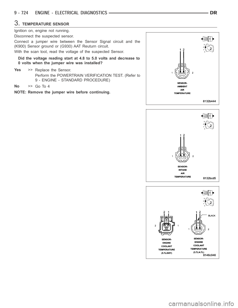
3.TEMPERATURE SENSOR
Ignition on, engine not running.
Disconnect the suspected sensor.
Connect a jumper wire between the Sensor Signal circuit and the
(K900) Sensor ground or (G930) AAT Reuturn circuit.
With the scan tool, read the voltage of the suspected Sensor.
Did the voltage reading start at 4.8 to 5.0 volts and decrease to
0 volts when the jumper wire was installed?
Ye s>>
Replace the Sensor.
Perform the POWERTRAIN VERIFICATION TEST. (Refer to
9 - ENGINE - STANDARD PROCEDURE)
No>>
Go To 4
NOTE: Remove the jumper wire before continuing.
Page 34 of 5267
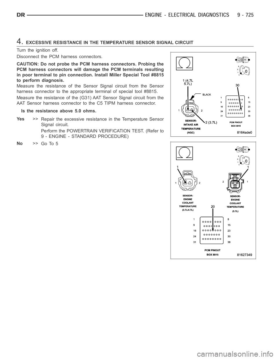
4.EXCESSIVE RESISTANCE IN THE TEMPERATURE SENSOR SIGNAL CIRCUIT
Turn the ignition off.
Disconnect the PCM harness connectors.
CAUTION: Do not probe the PCM harness connectors. Probing the
PCM harness connectors will damage the PCM terminals resulting
in poor terminal to pin connection. Install Miller Special Tool #8815
to perform diagnosis.
Measure the resistance of the Sensor Signal circuit from the Sensor
harness connector to the appropriate terminal of special tool #8815.
Measure the resistance of the (G31) AAT Sensor Signal circuit from the
AAT Sensor harness connector to the C5 TIPM harness connector.
Is the resistance above 5.0 ohms.
Ye s>>
Repair the excessive resistance in the Temperature Sensor
Signal circuit.
Perform the POWERTRAIN VERIFICATION TEST. (Refer to
9 - ENGINE - STANDARD PROCEDURE)
No>>
Go To 5
Page 94 of 5267
Theory of Operation
TheEGRvalvehasapositionsensorandthe EGR position rationality is designed to make sure that the valve
moves freely within its operating range. Closed valve position referencecheck verifies that the valve is within its
allowable upper and lower limits. The EGR position rationality test looksfor a sustained error relative to commanded
valve position.
When Monitored:
Engine running.
Set Condition:
The EGR flow or valve movement is not what is expected. A rationality error has been detected for the EGR
Open Position Performance. Two trip fault.
Possible Causes
EXCESSIVE RESISTANCE IN THE (F856) 5-VOLT SUPPLY CIRCUIT
(K35) EGR SOLENOID CONTROL CIRCUIT OPEN
(K34) EGR SENSOR SIGNAL CIRCUIT SHORTED TO GROUND
EGR SOLENOID ASSEMBLY
PCM
Always perform the Pre-Diagnostic Troubleshooting procedure before proceeding. (Refer to 9 - ENGINE -
DIAGNOSIS AND TESTING).
Diagnostic Test
1.ACTIVE DTC
Ignition on, engine not running.
With a scan tool, read DTCs.
Is the DTC active at this time?
Ye s>>
Go To 2
No>>
Refer to the INTERMITTENT CONDITION Diagnostic Procedure.
Perform the POWERTRAIN VERIFICATION TEST. (Refer to 9 - ENGINE - STANDARD PROCEDURE)
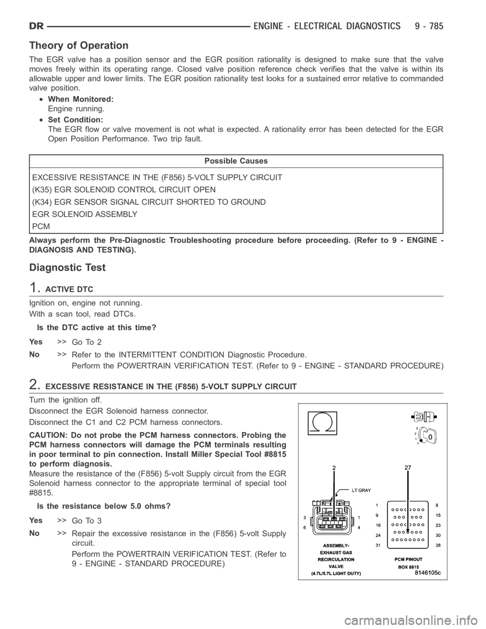
2.EXCESSIVE RESISTANCE IN THE (F856) 5-VOLT SUPPLY CIRCUIT
Turn the ignition off.
Disconnect the EGR Solenoid harness connector.
Disconnect the C1 and C2 PCM harness connectors.
CAUTION: Do not probe the PCM harness connectors. Probing the
PCM harness connectors will damage the PCM terminals resulting
in poor terminal to pin connection. Install Miller Special Tool #8815
to perform diagnosis.
Measure the resistance of the (F856) 5-volt Supply circuit from the EGR
Solenoid harness connector to the appropriate terminal of special tool
#8815.
Is the resistance below 5.0 ohms?
Ye s>>
Go To 3
No>>
Repair the excessive resistance in the (F856) 5-volt Supply
circuit.
Perform the POWERTRAIN VERIFICATION TEST. (Refer to
9 - ENGINE - STANDARD PROCEDURE)
Page 95 of 5267
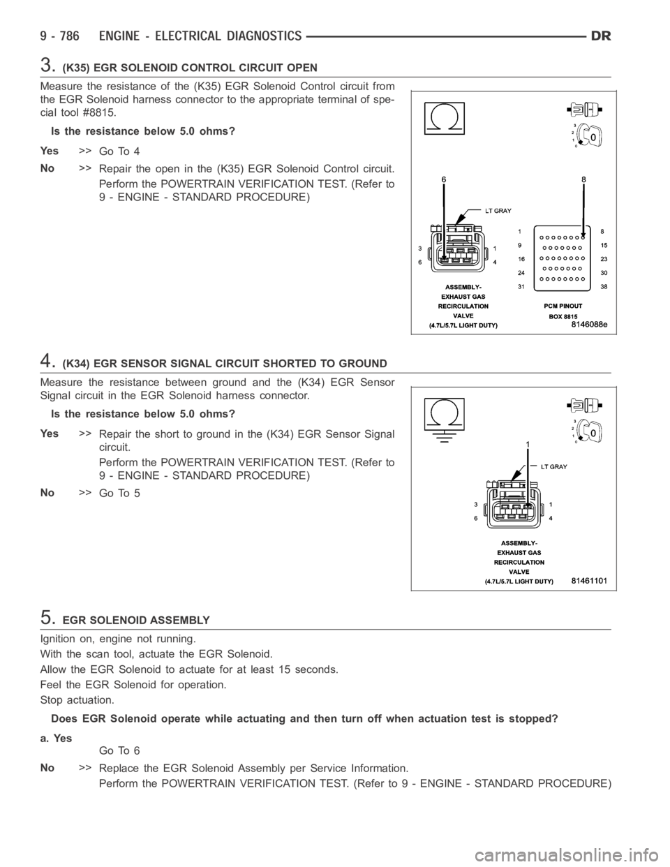
3.(K35) EGR SOLENOID CONTROL CIRCUIT OPEN
Measure the resistance of the (K35) EGR Solenoid Control circuit from
the EGR Solenoid harness connector to the appropriate terminal of spe-
cial tool #8815.
Is the resistance below 5.0 ohms?
Ye s>>
Go To 4
No>>
Repair the open in the (K35) EGR Solenoid Control circuit.
Perform the POWERTRAIN VERIFICATION TEST. (Refer to
9 - ENGINE - STANDARD PROCEDURE)
4.(K34) EGR SENSOR SIGNAL CIRCUIT SHORTED TO GROUND
Measure the resistance between ground and the (K34) EGR Sensor
Signal circuit in the EGR Solenoid harness connector.
Is the resistance below 5.0 ohms?
Ye s>>
Repair the short to ground in the (K34) EGR Sensor Signal
circuit.
Perform the POWERTRAIN VERIFICATION TEST. (Refer to
9 - ENGINE - STANDARD PROCEDURE)
No>>
Go To 5
5.EGR SOLENOID ASSEMBLY
Ignition on, engine not running.
With the scan tool, actuate the EGR Solenoid.
Allow the EGR Solenoid to actuate for at least 15 seconds.
Feel the EGR Solenoid for operation.
Stop actuation.
Does EGR Solenoid operate while actuating and then turn off when actuationtest is stopped?
a. Yes
Go To 6
No>>
Replace the EGR Solenoid Assembly per Service Information.
Perform the POWERTRAIN VERIFICATION TEST. (Refer to 9 - ENGINE - STANDARD PROCEDURE)
Page 125 of 5267
When Monitored:
Ignition on. In plant mode only.
Set Condition:
PCM recognizes the Brake Pedal couldnot electrically indicate the applied (On) position with both switch
inputs. One trip fault.
Possible Causes
(B29) BRAKE SWITCH NO.1 SIGNAL CIRCUIT OPEN
(V32) BRAKE SWITCH NO.2 SIGNAL CIRCUIT OPEN
STOP LAMP SWITCH
PCM
Always perform the Pre-Diagnostic Troubleshooting procedure before proceeding. (Refer to 9 - ENGINE -
DIAGNOSIS AND TESTING).
Diagnostic Test
1.ACTIVE DTC
NOTE: Make sure the Stop Lamp Switch is adjusted properly before continuing.
Ignition on, engine not running.
With a scan tool, read DTCs.
Is the DTC active at this time?
Ye s>>
Go To 2
No>>
Refer to the INTERMITTENT CONDITION Diagnostic Procedure.
Perform the POWERTRAIN VERIFICATION TEST. (Refer to 9 - ENGINE - STANDARD PROCEDURE)
2.STOP LAMP SWITCH OPERATION
Turn the ignition off.
Disconnect the Stop Lamp Switch harness connector.
Measure the resistance between the (Z429) Ground circuit terminal and the(B29) Brake Switch No.1 Signal terminal
in the Stop Lamp Switch.
Apply and release the brake pedal while monitoring the ohmmeter.
Does the resistance change from below 5.0 ohms to open circuit when pressingandreleasingthe
brake pedal switch?
Ye s>>
Go To 3
No>>
Replace the Stop Lamp Switch.
Perform the POWERTRAIN VERIFICATION TEST. (Refer to 9 - ENGINE - STANDARD PROCEDURE)
3.STOP LAMP SWITCH OPERATION
Measure the resistance between the (V30) Fused Ignition Switch Output terminal and the (V32) Brake Switch No.2
Signal circuit terminal in the Stop Lamp Switch.
Apply and release the brake pedal while monitoring the ohmmeter.
Does the resistance change from below 5.0 ohms to open circuit when pressingandreleasingtheStop
Lamp switch?
Ye s>>
Go To 4
No>>
Replace the Stop Lamp Switch.
Perform the POWERTRAIN VERIFICATION TEST. (Refer to 9 - ENGINE - STANDARD PROCEDURE)