DODGE SPRINTER 2006 1.G Owners Manual
Manufacturer: DODGE, Model Year: 2006, Model line: SPRINTER, Model: DODGE SPRINTER 2006 1.GPages: 330, PDF Size: 10.82 MB
Page 211 of 330

STARTING AND OPERATING 211
5
Diesel Fuels for Use at Very Low Temperatures
At very low temperatures the fluidity of No. 2 diesel
fuel may become insufficient due to parraffin
separation. For this reason the vehicle comes equipped
with a fuel preheater. It permits a troublefree engine
operation to a temperature of approximately 14 °F (–
10 °C) when using No. 2 diesel fuel.
To avoid malfunctions, No. 2 diesel fuel of a lowered
cloud point is marketed during the cold season.
At temperatures below 14 °F (–10 °C) use winterized or
No. 1 diesel fuel only. If not available, a certain
quantity of fuel flow improver may be added. Mixing
only to be done within the vehicle’s fuel tank.
Engine power may drop according to the proportion of
fuel flow improver. For this reason, keep percentage of
fuel flow improver added to the minimum
necessitated by the ambient temperature.
Even in extreme climatic conditions, the maximum
mixture ratio should not exceed 50%
Adding of kerosene to diesel fuel is not recommended
even at low temperatures.The following information can be used as a reference,
if adding of kerosene becomes necessary. The mixing
ratios shown refer to the total mixture.
Ambient temperature:
14 °F to –4 °F (–10 °C to –20 °C)
No. 2 Diesel Fuel: 70%
Kerosene: 30%
Ambient temperature:
below –4 °F to (–20 °C)
No. 2 Diesel Fuel: 50 %
Kerosene: 50 %
Even in extreme climatic conditions, the maximum
mixture ratio should not exceed 50 %.
Adding of kerosene to No. 1 diesel fuel is not
recommended even at low temperatures.
Do not blend other specific fuel additives with diesel
fuel except for fuel flow improver. They only result in
unnecessary cost, and may be harmful to the engine
operation.
CAUTION!
Damage or malfunctions resulting from poor fuel
quality or from blending specific fuel additives
are not covered by the Sprinter Warranty.
Page 212 of 330

212 STARTING AND OPERATING
REFUELING
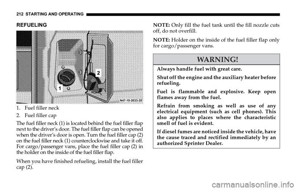
1. Fuel filler neck
2. Fuel filler cap
The fuel filler neck (1) is located behind the fuel filler flap
next to the driver’s door. The fuel filler flap can be opened
when the driver’s door is open. Turn the fuel filler cap (2)
on the fuel filler neck (1) counterclockwise and take it off.
For cargo/passenger vans, place the fuel filler cap (2) in
the holder on the inside of the fuel filler flap.
When you have finished refueling, install the fuel filler
cap (2).NOTE: Only fill the fuel tank until the fill nozzle cuts
off, do not overfill.
NOTE: Holder on the inside of the fuel filler flap only
for cargo/passenger vans.
WARNING!
Always handle fuel with great care.
Shut off the engine and the auxiliary heater before
refueling.
Fuel is flammable and explosive. Keep open
flames away from the fuel.
Refrain from smoking as well as use of any
electrical equipment (such as cell phones). This
also applies to places where the characteristic
smell of fuel is evident.
If diesel fumes are noticed inside the vehicle, have
the cause traced and rectified immediately by an
authorized Sprinter Dealer.
Page 213 of 330

STARTING AND OPERATING 213
5
Capacity
Fuel tank including reserve fuel about 26.4 US gal
(100 l).
PROGRAMMED TOP SPEED (OPTIONAL)
NOTE: The top speed of this vehicle can be
electronically limited to a speed between 19 mph
(30 km / h) and 82 mph (132 km / h). The vehicle’s
electronic speed controller should be programmed
only by a qualified technician by an authorized
Sprinter Dealer.
When programming the electronic speed controller,
the circumference of the specific tires actually mounted
on the vehicle must be determined and that
circumference must be correctly programmed into the
vehicle’s electronic speed controller. It is critical that
the correct tire circumference be programmed
accurately into the vehicle’s electronic speed
controller. Accurate tire circumference information
should be confirmed each time the electronic speed
controller is programmed and each time new wheels or
tires are mounted on the vehicle.
WARNING!
Possible tire damage resulting in serious personal
injury or death may occur if the vehicle’s electron-
ic speed controller is programmed at a speed
above the maximum speed allowed by the manu-
facturer of the specific tires mounted on the vehi-
cle. The maximum speed of the tires prescribed by
the tire manufacturer must be determined and ac-
curately programmed into the electronic speed
controller. The electronic speed controller must
never be programmed at a speed greater than the
maximum allowable tire speed as prescribed by
the manufacturer of the specific tires mounted on
the vehicle.
Page 214 of 330

214 STARTING AND OPERATING
BLEEDING DIESEL FUEL SYSTEM
If the fuel tank was run empty, the diesel fuel system
must be bled after refueling before starting the engine.
Turn the key in the ignition lock to position 2 for at
least 30 seconds.
Return the key to position 0.
Start the engine three to four times.
The malfunction indicator light (MIL) ± must go
out.
NOTE: Too many attempts to start the engine could
drain the battery. If the engine does not start after
several attempts, consult an authorized Sprinter
Dealer.DRAINING FUEL FILTER WITH WATER
SEPARATOR
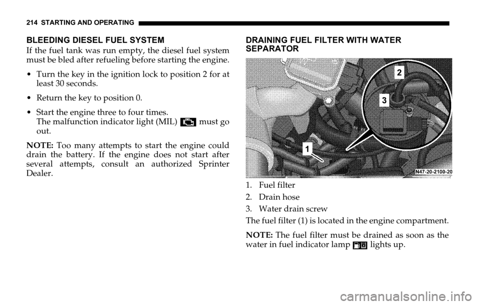
1. Fuel filter
2. Drain hose
3. Water drain screw
The fuel filter (1) is located in the engine compartment.
NOTE: The fuel filter must be drained as soon as the
water in fuel indicator lamp lights up.
Page 215 of 330

STARTING AND OPERATING 215
5
NOTE: Prior to opening water drain screw (3), place a
suitable receptacle underneath the drain hose (2). Turn
water drain screw (3) on and off only by hand.
Diesel fuels and diesel fuel mixtures must be disposed
of properly; we recommend water be drained from fuel
filters by an authorized Sprinter Dealer.
Draining Fuel Filter
Stop the engine.
Shift gear selector lever to ‘‘P’’ position.
Open the hood.
Place a suitable receptacle underneath the drain
hose (2).
Turn the key in the ignition lock to position 2. Open immediately the water drain screw (3) about 1
turn (counterclockwise) until fluid emerges. Ensure
that the fluid is collected in the receptacle.
Close the water drain screw (3) as soon as about 0.25
US qt (0.2 liters) are emerged.
After draining, return the key in the ignition lock to
position 0.
Dispose of the collected fluid in an environmentally
responsible manner.
If the filter is still saturated, drain the filter once
more.
After draining, the engine may run briefly but stall for
lack of fuel. If this occurs, bleed the system.
NOTE: Should the water in the fuel indicator lamp
still not go out after the fuel filter has been drained
twice, the cause should be examined by an authorized
Sprinter Dealer.
CAUTION!
Delaying draining of the fuel filter for a
considerable time after the indicator lamp lights
up may lead to engine damage.
Page 216 of 330

216 STARTING AND OPERATING
Bleeding the Diesel Fuel System
The diesel fuel system must be bled before starting the
engine.
Turn the key in the ignition lock position 2 for at
least 30 seconds.
Return the key to position 0.
Start the engine three to four times. The engine
control unit indicator lamp± must go out.
NOTE: Too many attempts to start the engine could
drain the battery. If the engine does not start after
several attempts, consult an authorized Sprinter
Dealer.PERMISSIBLE ROOF LOAD
The maximum permissible roof load is:
Vehicles with low roof 660 lbs (300 kg)
Vehicles with high roof 330 lbs (150 kg)
The weight of any load carried on the roof,
including the roof rack, must not exceed the
maximum permissible roof load.
LOADING THE VEHICLE
Two labels on the vehicle show how much weight it
may properly carry.
The Tire and Loading Information placard can be
found on the driver’s door B-pillar. This placard
tells you important information about the number
of people that can be in the vehicle and the total
weight that can be carried in the vehicle. It also
contains information on the proper size and
recommended tire inflation pressures for the
original equipment tires on the vehicle.
The Certification Label can be found below the
driver’s seat on an outward facing position of the
mounting pillar. It tells you about the gross weight
Page 217 of 330

STARTING AND OPERATING 217
5
capacity of your vehicle, called the Gross Vehicle
Weight Rating (GVWR). The GVWR includes the
weight of the vehicle, all occupants, fuel and cargo.
The Certification Label also tells you about the front
and rear axle weight capacity, called the Gross Axle
Weight Rating (GAWR). The GAWR is the total
allowable weight that can be carried by a single axle
(front or rear). Never exceed the GVWR or GAWR
for either the front axle or rear axle.
Following is a discussion on how to work with the
information contained on the two placards with
regards to loading your Sprinter vehicle.Tire and Loading Information
WARNING!
Do not overload the tires by exceeding the speci-
fied load limit as indicated on the Tire and Load-
ing Information placard on the driver’s door B-
pillar. Overloading the tires can overheat them,
possibly causing a blowout. Overloading the tires
can also result in handling or steering problems,
or brake failure.
Overloading of tires is dangerous. Overloading
can cause tire failure, affect vehicle handling, and
increase the stopping distance. Use tires of the
recommended load capacity for the vehicle. Never
overload them.
The vehicle maximum load on the tire must not
exceed the load carrying capacity of the tire on
your vehicle. You will not exceed the tire’s load
carrying capacity if you adhere to the loading
conditions, tire size and cold tire inflation
pressures specified on the Tire and Loading
Information placard and this section.
Page 218 of 330

218 STARTING AND OPERATING
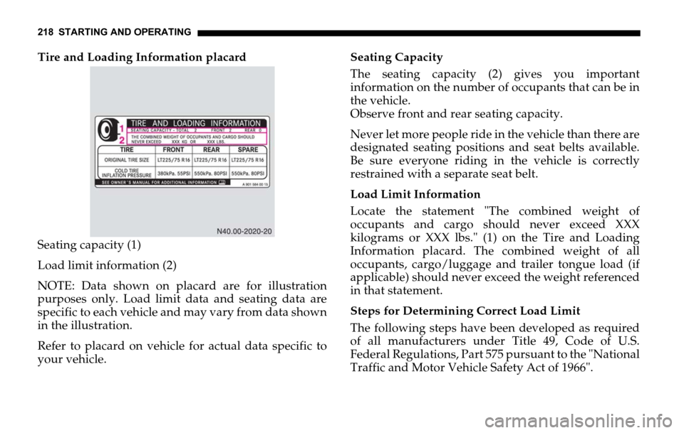
Tire and Loading Information placard
Seating capacity (1)
Load limit information (2)
NOTE: Data shown on placard are for illustration
purposes only. Load limit data and seating data are
specific to each vehicle and may vary from data shown
in the illustration.
Refer to placard on vehicle for actual data specific to
your vehicle.Seating Capacity
The seating capacity (2) gives you important
information on the number of occupants that can be in
the vehicle.
Observe front and rear seating capacity.
Never let more people ride in the vehicle than there are
designated seating positions and seat belts available.
Be sure everyone riding in the vehicle is correctly
restrained with a separate seat belt.
Load Limit Information
Locate the statement "The combined weight of
occupants and cargo should never exceed XXX
kilograms or XXX lbs." (1) on the Tire and Loading
Information placard. The combined weight of all
occupants, cargo/luggage and trailer tongue load (if
applicable) should never exceed the weight referenced
in that statement.
Steps for Determining Correct Load Limit
The following steps have been developed as required
of all manufacturers under Title 49, Code of U.S.
Federal Regulations, Part 575 pursuant to the "National
Traffic and Motor Vehicle Safety Act of 1966".
Page 219 of 330

STARTING AND OPERATING 219
5
Step 1
Locate the statement "The combined weight of
occupants and cargo should never exceed XXX kg or
XXX lbs." on your vehicle’s placard.
Step 2
Determine the combined weight of the driver
andpassengers that will be riding in your vehicle.
Step 3
Subtract the combined weight of the driver and
passengers from XXX kilograms or XXX lbs.
Step 4
The resulting figure equals the available amount of
cargo and luggage load capacity. For example, if the
"XXX" amount equals 1400 lbs. and there will be five
150 lbs. passengers in your vehicle, the amount of
available cargo and luggage load capacity is 650 lbs.
(1400 – 750 (5 x 150) = 650 lbs.)
Step 5
Determine the combined weight of luggage and
cargo being loaded on the vehicle. That weight may
not safely exceed the available cargo and luggage
load capacity calculated in step 4.Step 6 (if applicable)
If your vehicle will be towing a trailer, load from
your trailer will be transferred to your vehicle.
Refer to "Trailer Tongue Load" to determine how
this reduces the available cargo and luggage load
capacity of your vehicle.
The following table shows examples on how to
calculate total load, cargo load and towing capacities
with varying seating configurations and number and
size of occupants.
The following examples use a load limit of 1500 lbs.
NOTE: This is for illustration purposes only. Make
sure you are using the actual load limit for your vehicle
stated on the vehicle’s Tire and Loading Information
placard.
Page 220 of 330

220 STARTING AND OPERATING
The higher the weight of all occupants, the less cargo
and luggage load capacity is available.
For more information, refer to "Trailer Tongue Load".
ExampleCombined
weight limit of
occupants and
cargo from
placardNumber of
occupants
(driver and
passengers)Seating
configurationOccupants weightCombined
weight of all
occupantsAvailable cargo/luggage
and trailer tongue weight
(total load limit from
placard minus combined
weight of all occupants)
1 1500 lbs 5 front: 2
rear: 3Occupant 1: 150 lbs
Occupant 2: 180 lbs
Occupant 3: 160 lbs
Occupant 4: 140 lbs
Occupant 5: 120 lbs.750 lbs 1500 lbs – 750 lbs = 750 lbs
2 1500 lbs 3 front: 1
rear: 2Occupant 1: 200 lbs
Occupant 2: 190 lbs
Occupant 3: 150 lbs 540 lbs 1500 lbs – 540 lbs = 960 lbs
3 1500 lbs 1 front: 1 Occupant 1: 150 lbs 150 lbs 1500 lbs – 150 lbs = 1350 lbs