DODGE TOWN AND COUNTRY 2001 Service Manual
Manufacturer: DODGE, Model Year: 2001, Model line: TOWN AND COUNTRY, Model: DODGE TOWN AND COUNTRY 2001Pages: 2321, PDF Size: 68.09 MB
Page 1211 of 2321
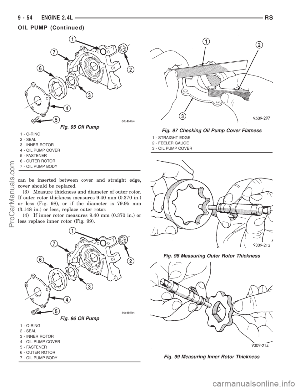
can be inserted between cover and straight edge,
cover should be replaced.
(3) Measure thickness and diameter of outer rotor.
If outer rotor thickness measures 9.40 mm (0.370 in.)
or less (Fig. 98), or if the diameter is 79.95 mm
(3.148 in.) or less, replace outer rotor.
(4) If inner rotor measures 9.40 mm (0.370 in.) or
less replace inner rotor (Fig. 99).
Fig. 95 Oil Pump
1 - O-RING
2 - SEAL
3 - INNER ROTOR
4 - OIL PUMP COVER
5 - FASTENER
6 - OUTER ROTOR
7 - OIL PUMP BODY
Fig. 96 Oil Pump
1 - O-RING
2 - SEAL
3 - INNER ROTOR
4 - OIL PUMP COVER
5 - FASTENER
6 - OUTER ROTOR
7 - OIL PUMP BODY
Fig. 97 Checking Oil Pump Cover Flatness
1 - STRAIGHT EDGE
2 - FEELER GAUGE
3 - OIL PUMP COVER
Fig. 98 Measuring Outer Rotor Thickness
Fig. 99 Measuring Inner Rotor Thickness
9 - 54 ENGINE 2.4LRS
OIL PUMP (Continued)
ProCarManuals.com
Page 1212 of 2321
ASSEMBLY
(1) Assemble pump, using new parts as required.
Install the inner rotor with chamfer facing the
cast iron oil pump cover.
(2) Prime oil pump before installation by filling
rotor cavity with engine oil.
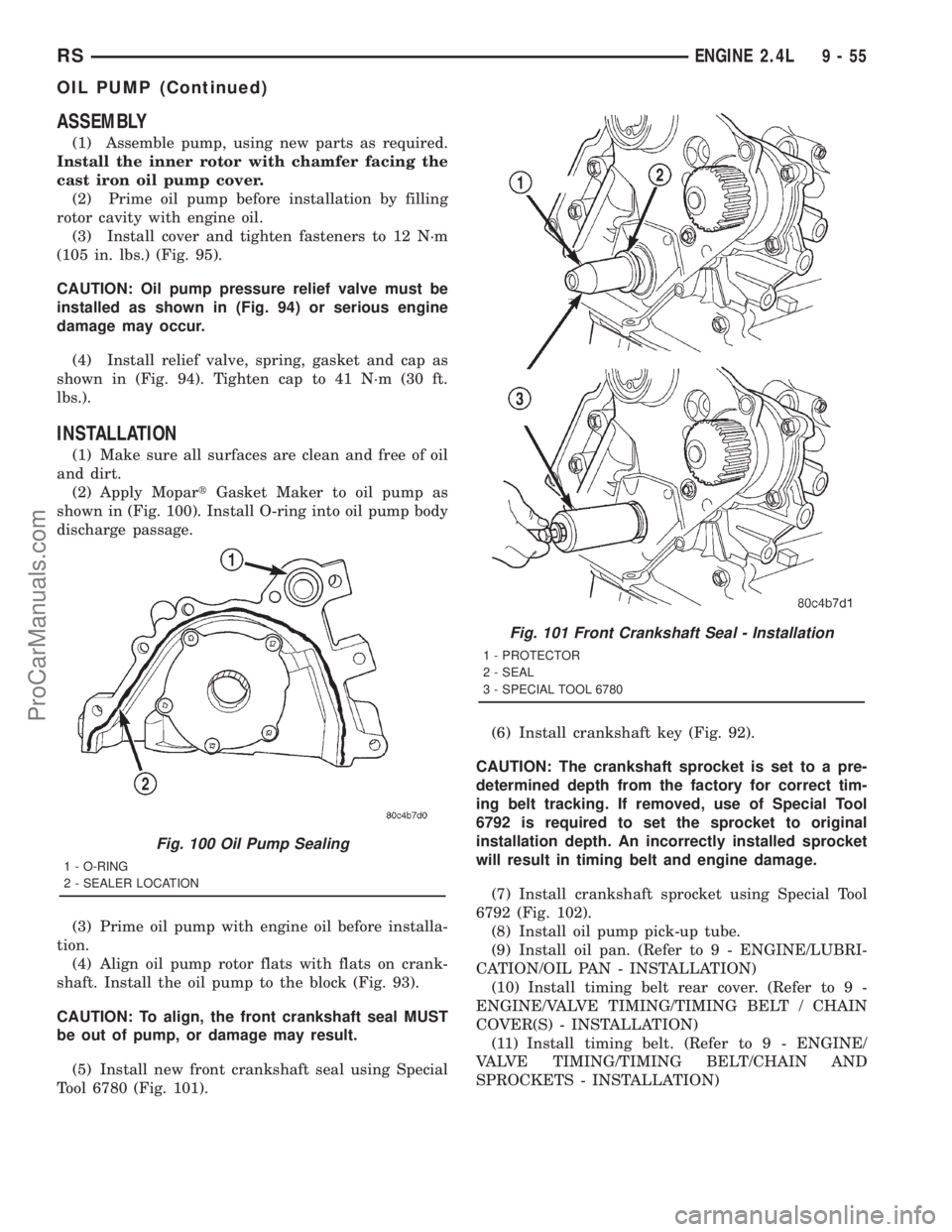
(3) Install cover and tighten fasteners to 12 N´m
(105 in. lbs.) (Fig. 95).
CAUTION: Oil pump pressure relief valve must be
installed as shown in (Fig. 94) or serious engine
damage may occur.
(4) Install relief valve, spring, gasket and cap as
shown in (Fig. 94). Tighten cap to 41 N´m (30 ft.
lbs.).
INSTALLATION
(1) Make sure all surfaces are clean and free of oil
and dirt.
(2) Apply MopartGasket Maker to oil pump as
shown in (Fig. 100). Install O-ring into oil pump body
discharge passage.
(3) Prime oil pump with engine oil before installa-
tion.
(4) Align oil pump rotor flats with flats on crank-
shaft. Install the oil pump to the block (Fig. 93).
CAUTION: To align, the front crankshaft seal MUST
be out of pump, or damage may result.
(5) Install new front crankshaft seal using Special
Tool 6780 (Fig. 101).(6) Install crankshaft key (Fig. 92).
CAUTION: The crankshaft sprocket is set to a pre-
determined depth from the factory for correct tim-
ing belt tracking. If removed, use of Special Tool
6792 is required to set the sprocket to original
installation depth. An incorrectly installed sprocket
will result in timing belt and engine damage.
(7) Install crankshaft sprocket using Special Tool
6792 (Fig. 102).
(8) Install oil pump pick-up tube.
(9) Install oil pan. (Refer to 9 - ENGINE/LUBRI-
CATION/OIL PAN - INSTALLATION)
(10) Install timing belt rear cover. (Refer to 9 -
ENGINE/VALVE TIMING/TIMING BELT / CHAIN
COVER(S) - INSTALLATION)
(11) Install timing belt. (Refer to 9 - ENGINE/
VALVE TIMING/TIMING BELT/CHAIN AND
SPROCKETS - INSTALLATION)
Fig. 100 Oil Pump Sealing
1 - O-RING
2 - SEALER LOCATION
Fig. 101 Front Crankshaft Seal - Installation
1 - PROTECTOR
2 - SEAL
3 - SPECIAL TOOL 6780
RSENGINE 2.4L9-55
OIL PUMP (Continued)
ProCarManuals.com
Page 1213 of 2321
INTAKE MANIFOLD
DESCRIPTION
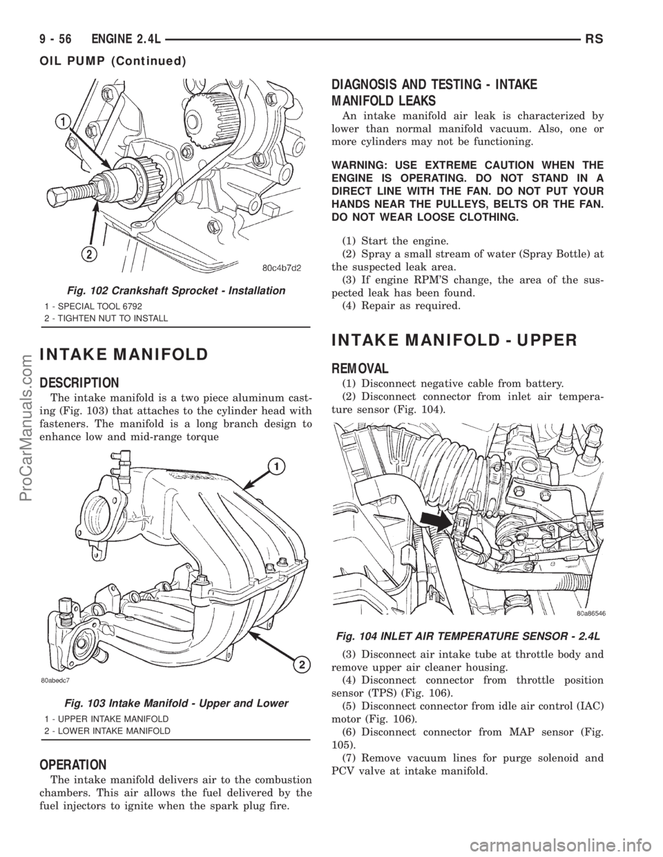
The intake manifold is a two piece aluminum cast-
ing (Fig. 103) that attaches to the cylinder head with
fasteners. The manifold is a long branch design to
enhance low and mid-range torque
OPERATION
The intake manifold delivers air to the combustion
chambers. This air allows the fuel delivered by the
fuel injectors to ignite when the spark plug fire.
DIAGNOSIS AND TESTING - INTAKE
MANIFOLD LEAKS
An intake manifold air leak is characterized by
lower than normal manifold vacuum. Also, one or
more cylinders may not be functioning.
WARNING: USE EXTREME CAUTION WHEN THE
ENGINE IS OPERATING. DO NOT STAND IN A
DIRECT LINE WITH THE FAN. DO NOT PUT YOUR
HANDS NEAR THE PULLEYS, BELTS OR THE FAN.
DO NOT WEAR LOOSE CLOTHING.
(1) Start the engine.
(2) Spray a small stream of water (Spray Bottle) at
the suspected leak area.
(3) If engine RPM'S change, the area of the sus-
pected leak has been found.
(4) Repair as required.
INTAKE MANIFOLD - UPPER
REMOVAL
(1) Disconnect negative cable from battery.
(2) Disconnect connector from inlet air tempera-
ture sensor (Fig. 104).
(3) Disconnect air intake tube at throttle body and
remove upper air cleaner housing.
(4) Disconnect connector from throttle position
sensor (TPS) (Fig. 106).
(5) Disconnect connector from idle air control (IAC)
motor (Fig. 106).
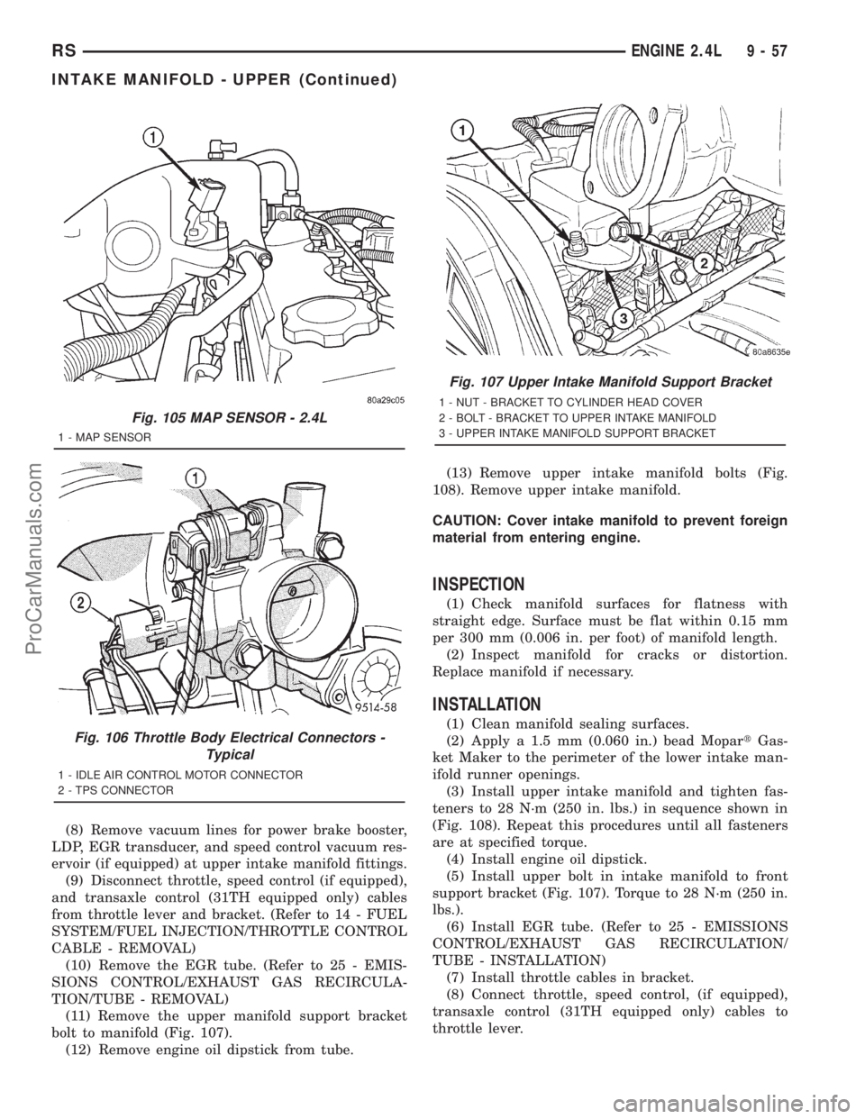
(6) Disconnect connector from MAP sensor (Fig.
105).
(7) Remove vacuum lines for purge solenoid and
PCV valve at intake manifold.
Fig. 102 Crankshaft Sprocket - Installation
1 - SPECIAL TOOL 6792
2 - TIGHTEN NUT TO INSTALL
Fig. 103 Intake Manifold - Upper and Lower
1 - UPPER INTAKE MANIFOLD
2 - LOWER INTAKE MANIFOLD
Fig. 104 INLET AIR TEMPERATURE SENSOR - 2.4L
9 - 56 ENGINE 2.4LRS
OIL PUMP (Continued)
ProCarManuals.com
Page 1214 of 2321
(8) Remove vacuum lines for power brake booster,
LDP, EGR transducer, and speed control vacuum res-
ervoir (if equipped) at upper intake manifold fittings.
(9) Disconnect throttle, speed control (if equipped),
and transaxle control (31TH equipped only) cables
from throttle lever and bracket. (Refer to 14 - FUEL
SYSTEM/FUEL INJECTION/THROTTLE CONTROL
CABLE - REMOVAL)
(10) Remove the EGR tube. (Refer to 25 - EMIS-
SIONS CONTROL/EXHAUST GAS RECIRCULA-
TION/TUBE - REMOVAL)
(11) Remove the upper manifold support bracket
bolt to manifold (Fig. 107).
(12) Remove engine oil dipstick from tube.(13) Remove upper intake manifold bolts (Fig.
108). Remove upper intake manifold.
CAUTION: Cover intake manifold to prevent foreign
material from entering engine.
INSPECTION
(1) Check manifold surfaces for flatness with
straight edge. Surface must be flat within 0.15 mm
per 300 mm (0.006 in. per foot) of manifold length.
(2) Inspect manifold for cracks or distortion.
Replace manifold if necessary.
INSTALLATION
(1) Clean manifold sealing surfaces.
(2) Apply a 1.5 mm (0.060 in.) bead MopartGas-
ket Maker to the perimeter of the lower intake man-
ifold runner openings.
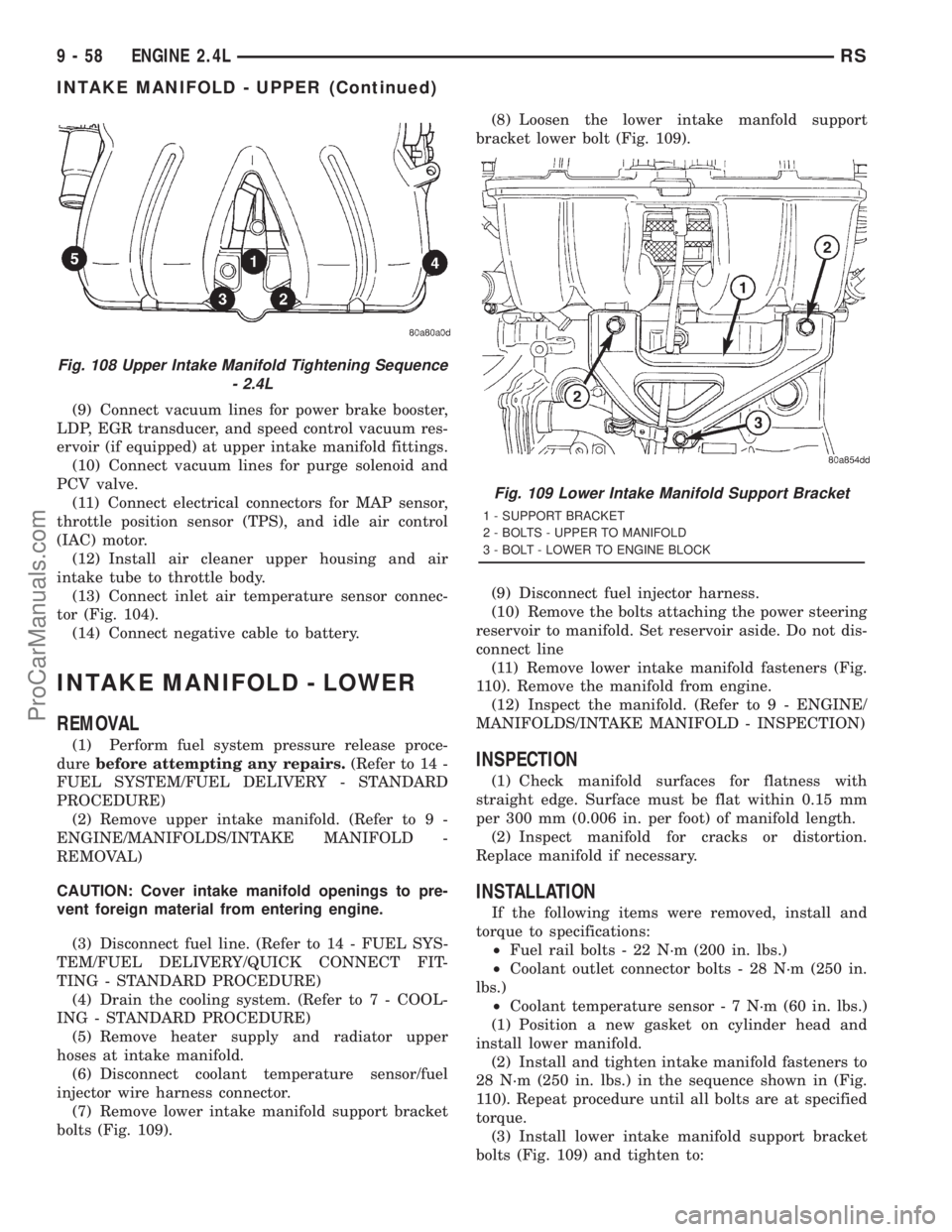
(3) Install upper intake manifold and tighten fas-
teners to 28 N´m (250 in. lbs.) in sequence shown in
(Fig. 108). Repeat this procedures until all fasteners
are at specified torque.
(4) Install engine oil dipstick.
(5) Install upper bolt in intake manifold to front
support bracket (Fig. 107). Torque to 28 N´m (250 in.
lbs.).
(6) Install EGR tube. (Refer to 25 - EMISSIONS
CONTROL/EXHAUST GAS RECIRCULATION/
TUBE - INSTALLATION)
(7) Install throttle cables in bracket.
(8) Connect throttle, speed control, (if equipped),
transaxle control (31TH equipped only) cables to
throttle lever.
Fig. 105 MAP SENSOR - 2.4L
1 - MAP SENSOR
Fig. 106 Throttle Body Electrical Connectors -
Typical
1 - IDLE AIR CONTROL MOTOR CONNECTOR
2 - TPS CONNECTOR
Fig. 107 Upper Intake Manifold Support Bracket
1 - NUT - BRACKET TO CYLINDER HEAD COVER
2 - BOLT - BRACKET TO UPPER INTAKE MANIFOLD
3 - UPPER INTAKE MANIFOLD SUPPORT BRACKET
RSENGINE 2.4L9-57
INTAKE MANIFOLD - UPPER (Continued)
ProCarManuals.com
Page 1215 of 2321
(9) Connect vacuum lines for power brake booster,
LDP, EGR transducer, and speed control vacuum res-
ervoir (if equipped) at upper intake manifold fittings.
(10) Connect vacuum lines for purge solenoid and
PCV valve.
(11) Connect electrical connectors for MAP sensor,
throttle position sensor (TPS), and idle air control
(IAC) motor.
(12) Install air cleaner upper housing and air
intake tube to throttle body.
(13) Connect inlet air temperature sensor connec-
tor (Fig. 104).
(14) Connect negative cable to battery.
INTAKE MANIFOLD - LOWER
REMOVAL
(1) Perform fuel system pressure release proce-
durebefore attempting any repairs.(Refer to 14 -
FUEL SYSTEM/FUEL DELIVERY - STANDARD
PROCEDURE)
(2) Remove upper intake manifold. (Refer to 9 -
ENGINE/MANIFOLDS/INTAKE MANIFOLD -
REMOVAL)
CAUTION: Cover intake manifold openings to pre-
vent foreign material from entering engine.
(3) Disconnect fuel line. (Refer to 14 - FUEL SYS-
TEM/FUEL DELIVERY/QUICK CONNECT FIT-
TING - STANDARD PROCEDURE)
(4) Drain the cooling system. (Refer to 7 - COOL-
ING - STANDARD PROCEDURE)
(5) Remove heater supply and radiator upper
hoses at intake manifold.
(6) Disconnect coolant temperature sensor/fuel
injector wire harness connector.
(7) Remove lower intake manifold support bracket
bolts (Fig. 109).(8) Loosen the lower intake manfold support
bracket lower bolt (Fig. 109).
(9) Disconnect fuel injector harness.
(10) Remove the bolts attaching the power steering
reservoir to manifold. Set reservoir aside. Do not dis-
connect line
(11) Remove lower intake manifold fasteners (Fig.
110). Remove the manifold from engine.
(12) Inspect the manifold. (Refer to 9 - ENGINE/
MANIFOLDS/INTAKE MANIFOLD - INSPECTION)
INSPECTION
(1) Check manifold surfaces for flatness with
straight edge. Surface must be flat within 0.15 mm
per 300 mm (0.006 in. per foot) of manifold length.
(2) Inspect manifold for cracks or distortion.
Replace manifold if necessary.
INSTALLATION
If the following items were removed, install and
torque to specifications:
²Fuel rail bolts - 22 N´m (200 in. lbs.)
²Coolant outlet connector bolts - 28 N´m (250 in.
lbs.)
²Coolant temperature sensor - 7 N´m (60 in. lbs.)
(1) Position a new gasket on cylinder head and
install lower manifold.
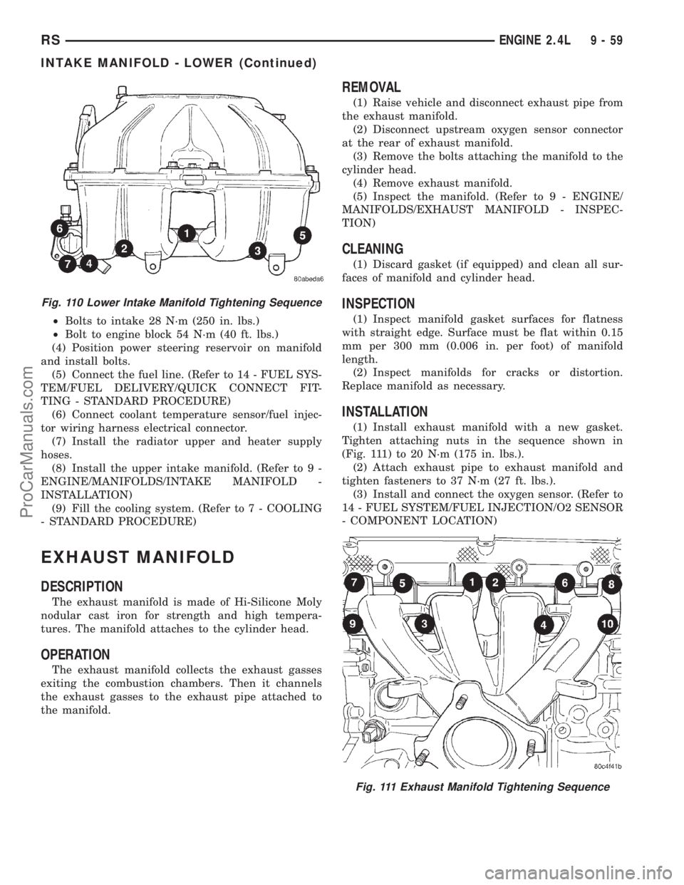
(2) Install and tighten intake manifold fasteners to
28 N´m (250 in. lbs.) in the sequence shown in (Fig.
110). Repeat procedure until all bolts are at specified
torque.
(3) Install lower intake manifold support bracket
bolts (Fig. 109) and tighten to:
Fig. 108 Upper Intake Manifold Tightening Sequence
- 2.4L
Fig. 109 Lower Intake Manifold Support Bracket
1 - SUPPORT BRACKET
2 - BOLTS - UPPER TO MANIFOLD
3 - BOLT - LOWER TO ENGINE BLOCK
9 - 58 ENGINE 2.4LRS
INTAKE MANIFOLD - UPPER (Continued)
ProCarManuals.com
Page 1216 of 2321
²Bolts to intake 28 N´m (250 in. lbs.)
²Bolt to engine block 54 N´m (40 ft. lbs.)
(4) Position power steering reservoir on manifold
and install bolts.
(5) Connect the fuel line. (Refer to 14 - FUEL SYS-
TEM/FUEL DELIVERY/QUICK CONNECT FIT-
TING - STANDARD PROCEDURE)
(6) Connect coolant temperature sensor/fuel injec-
tor wiring harness electrical connector.
(7) Install the radiator upper and heater supply
hoses.
(8) Install the upper intake manifold. (Refer to 9 -
ENGINE/MANIFOLDS/INTAKE MANIFOLD -
INSTALLATION)
(9) Fill the cooling system. (Refer to 7 - COOLING
- STANDARD PROCEDURE)
EXHAUST MANIFOLD
DESCRIPTION
The exhaust manifold is made of Hi-Silicone Moly
nodular cast iron for strength and high tempera-
tures. The manifold attaches to the cylinder head.
OPERATION
The exhaust manifold collects the exhaust gasses
exiting the combustion chambers. Then it channels
the exhaust gasses to the exhaust pipe attached to
the manifold.
REMOVAL
(1) Raise vehicle and disconnect exhaust pipe from
the exhaust manifold.
(2) Disconnect upstream oxygen sensor connector
at the rear of exhaust manifold.
(3) Remove the bolts attaching the manifold to the
cylinder head.
(4) Remove exhaust manifold.
(5) Inspect the manifold. (Refer to 9 - ENGINE/
MANIFOLDS/EXHAUST MANIFOLD - INSPEC-
TION)
CLEANING
(1) Discard gasket (if equipped) and clean all sur-
faces of manifold and cylinder head.
INSPECTION
(1) Inspect manifold gasket surfaces for flatness
with straight edge. Surface must be flat within 0.15
mm per 300 mm (0.006 in. per foot) of manifold
length.
(2) Inspect manifolds for cracks or distortion.
Replace manifold as necessary.
INSTALLATION
(1) Install exhaust manifold with a new gasket.
Tighten attaching nuts in the sequence shown in
(Fig. 111) to 20 N´m (175 in. lbs.).
(2) Attach exhaust pipe to exhaust manifold and
tighten fasteners to 37 N´m (27 ft. lbs.).
(3) Install and connect the oxygen sensor. (Refer to
14 - FUEL SYSTEM/FUEL INJECTION/O2 SENSOR
- COMPONENT LOCATION)
Fig. 110 Lower Intake Manifold Tightening Sequence
Fig. 111 Exhaust Manifold Tightening Sequence
RSENGINE 2.4L9-59
INTAKE MANIFOLD - LOWER (Continued)
ProCarManuals.com
Page 1217 of 2321
TIMING BELT COVER(S)
REMOVAL
FRONT COVER
(1) Remove crankshaft vibration damper. (Refer to
9 - ENGINE/ENGINE BLOCK/VIBRATION
DAMPER - REMOVAL)
(2) Remove generator drive belt tensioner assem-
bly. (Refer to 7 - COOLING/ACCESSORY DRIVE/
BELT TENSIONERS - REMOVAL)
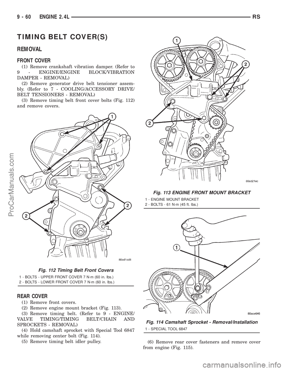
(3) Remove timing belt front cover bolts (Fig. 112)
and remove covers.
REAR COVER
(1) Remove front covers.
(2) Remove engine mount bracket (Fig. 113).
(3) Remove timing belt. (Refer to 9 - ENGINE/
VALVE TIMING/TIMING BELT/CHAIN AND
SPROCKETS - REMOVAL)
(4) Hold camshaft sprocket with Special Tool 6847
while removing center bolt (Fig. 114).
(5) Remove timing belt idler pulley.
(6) Remove rear cover fasteners and remove cover
from engine (Fig. 115).
Fig. 112 Timing Belt Front Covers
1 - BOLTS - UPPER FRONT COVER 7 N´m (60 in. lbs.)
2 - BOLTS - LOWER FRONT COVER 7 N´m (60 in. lbs.)
Fig. 113 ENGINE FRONT MOUNT BRACKET
1 - ENGINE MOUNT BRACKET
2 - BOLTS - 61 N´m (45 ft. lbs.)
Fig. 114 Camshaft Sprocket - Removal/Installation
1 - SPECIAL TOOL 6847
9 - 60 ENGINE 2.4LRS
ProCarManuals.com
Page 1218 of 2321
INSTALLATION
REAR COVER
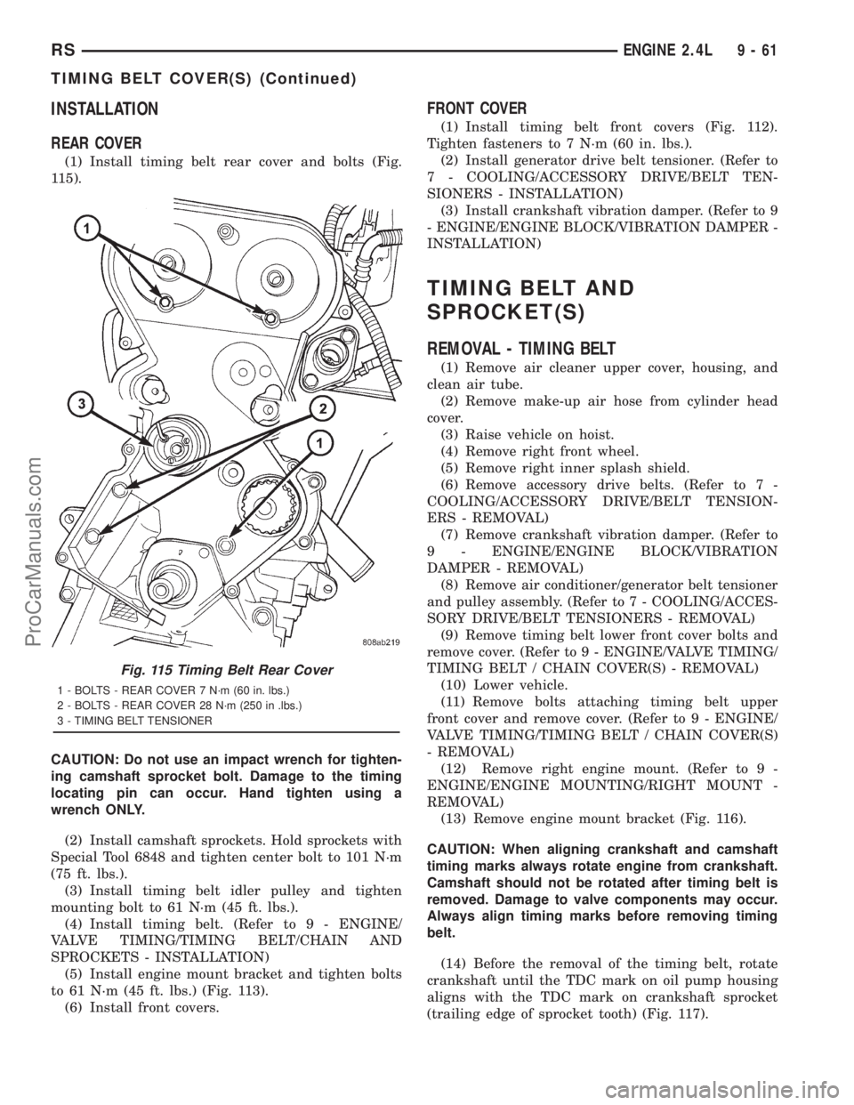
(1) Install timing belt rear cover and bolts (Fig.
115).
CAUTION: Do not use an impact wrench for tighten-
ing camshaft sprocket bolt. Damage to the timing
locating pin can occur. Hand tighten using a
wrench ONLY.
(2) Install camshaft sprockets. Hold sprockets with
Special Tool 6848 and tighten center bolt to 101 N´m
(75 ft. lbs.).
(3) Install timing belt idler pulley and tighten
mounting bolt to 61 N´m (45 ft. lbs.).
(4) Install timing belt. (Refer to 9 - ENGINE/
VALVE TIMING/TIMING BELT/CHAIN AND
SPROCKETS - INSTALLATION)
(5) Install engine mount bracket and tighten bolts
to 61 N´m (45 ft. lbs.) (Fig. 113).
(6) Install front covers.
FRONT COVER
(1) Install timing belt front covers (Fig. 112).
Tighten fasteners to 7 N´m (60 in. lbs.).
(2) Install generator drive belt tensioner. (Refer to
7 - COOLING/ACCESSORY DRIVE/BELT TEN-
SIONERS - INSTALLATION)
(3) Install crankshaft vibration damper. (Refer to 9
- ENGINE/ENGINE BLOCK/VIBRATION DAMPER -
INSTALLATION)
TIMING BELT AND
SPROCKET(S)
REMOVAL - TIMING BELT
(1) Remove air cleaner upper cover, housing, and
clean air tube.
(2) Remove make-up air hose from cylinder head
cover.
(3) Raise vehicle on hoist.
(4) Remove right front wheel.
(5) Remove right inner splash shield.
(6) Remove accessory drive belts. (Refer to 7 -
COOLING/ACCESSORY DRIVE/BELT TENSION-
ERS - REMOVAL)
(7) Remove crankshaft vibration damper. (Refer to
9 - ENGINE/ENGINE BLOCK/VIBRATION
DAMPER - REMOVAL)
(8) Remove air conditioner/generator belt tensioner
and pulley assembly. (Refer to 7 - COOLING/ACCES-
SORY DRIVE/BELT TENSIONERS - REMOVAL)
(9) Remove timing belt lower front cover bolts and
remove cover. (Refer to 9 - ENGINE/VALVE TIMING/
TIMING BELT / CHAIN COVER(S) - REMOVAL)
(10) Lower vehicle.
(11) Remove bolts attaching timing belt upper
front cover and remove cover. (Refer to 9 - ENGINE/
VALVE TIMING/TIMING BELT / CHAIN COVER(S)
- REMOVAL)
(12) Remove right engine mount. (Refer to 9 -
ENGINE/ENGINE MOUNTING/RIGHT MOUNT -
REMOVAL)
(13) Remove engine mount bracket (Fig. 116).
CAUTION: When aligning crankshaft and camshaft
timing marks always rotate engine from crankshaft.
Camshaft should not be rotated after timing belt is
removed. Damage to valve components may occur.
Always align timing marks before removing timing
belt.
(14) Before the removal of the timing belt, rotate
crankshaft until the TDC mark on oil pump housing
aligns with the TDC mark on crankshaft sprocket
(trailing edge of sprocket tooth) (Fig. 117).
Fig. 115 Timing Belt Rear Cover
1 - BOLTS - REAR COVER 7 N´m (60 in. lbs.)
2 - BOLTS - REAR COVER 28 N´m (250 in .lbs.)
3 - TIMING BELT TENSIONER
RSENGINE 2.4L9-61
TIMING BELT COVER(S) (Continued)
ProCarManuals.com
Page 1219 of 2321
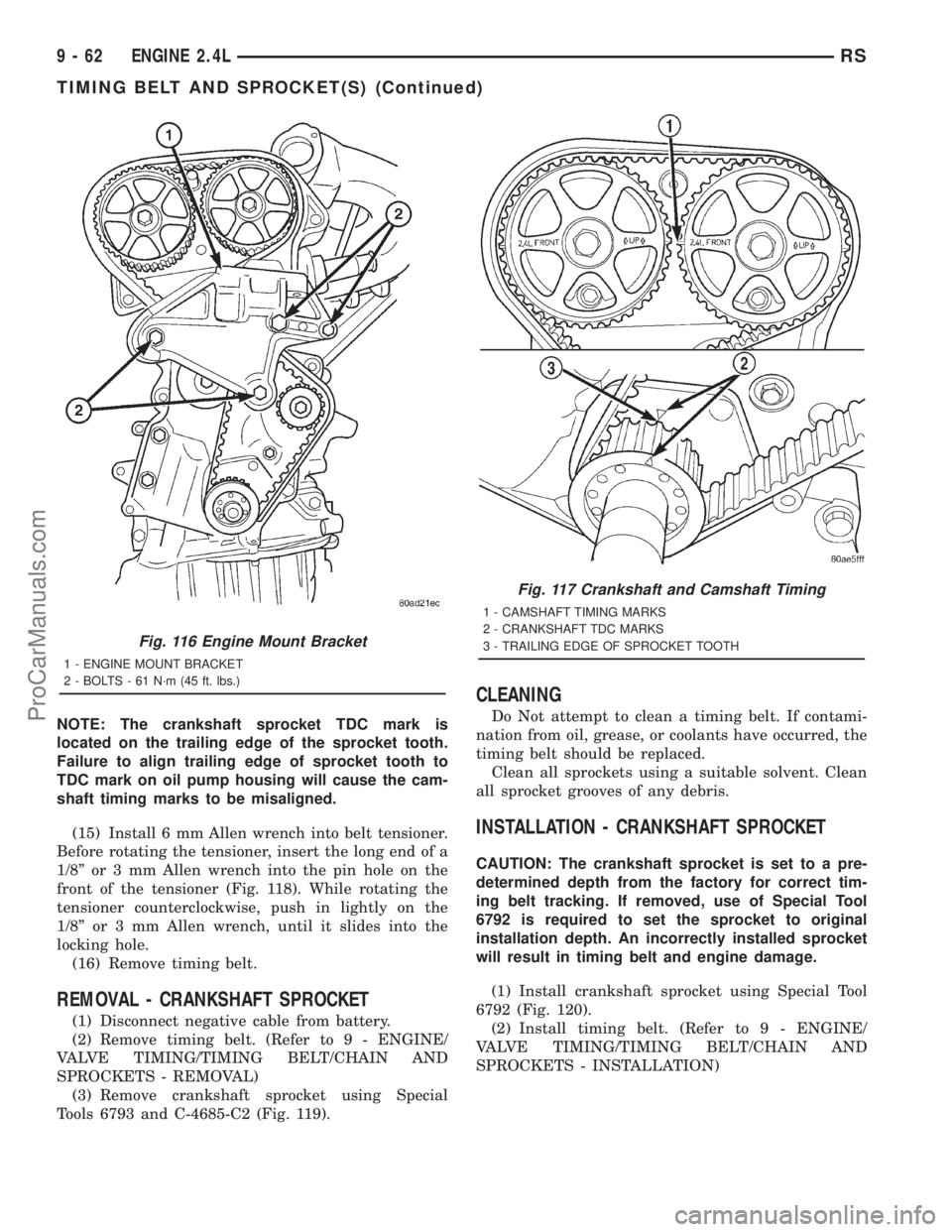
NOTE: The crankshaft sprocket TDC mark is
located on the trailing edge of the sprocket tooth.
Failure to align trailing edge of sprocket tooth to
TDC mark on oil pump housing will cause the cam-
shaft timing marks to be misaligned.
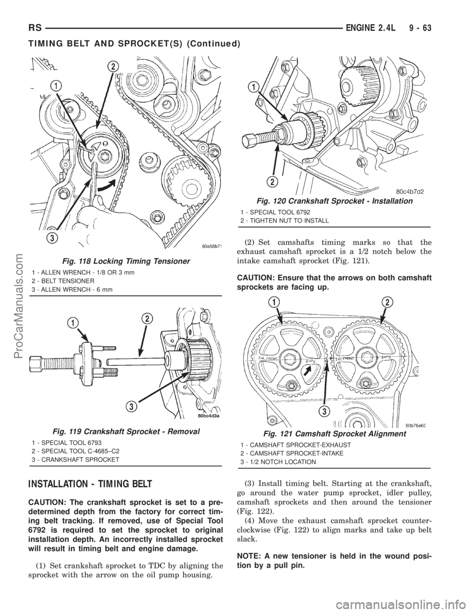
(15) Install 6 mm Allen wrench into belt tensioner.
Before rotating the tensioner, insert the long end of a
1/8º or 3 mm Allen wrench into the pin hole on the
front of the tensioner (Fig. 118). While rotating the
tensioner counterclockwise, push in lightly on the
1/8º or 3 mm Allen wrench, until it slides into the
locking hole.
(16) Remove timing belt.
REMOVAL - CRANKSHAFT SPROCKET
(1) Disconnect negative cable from battery.
(2) Remove timing belt. (Refer to 9 - ENGINE/
VALVE TIMING/TIMING BELT/CHAIN AND
SPROCKETS - REMOVAL)
(3) Remove crankshaft sprocket using Special
Tools 6793 and C-4685-C2 (Fig. 119).
CLEANING
Do Not attempt to clean a timing belt. If contami-
nation from oil, grease, or coolants have occurred, the
timing belt should be replaced.
Clean all sprockets using a suitable solvent. Clean
all sprocket grooves of any debris.
INSTALLATION - CRANKSHAFT SPROCKET
CAUTION: The crankshaft sprocket is set to a pre-
determined depth from the factory for correct tim-
ing belt tracking. If removed, use of Special Tool
6792 is required to set the sprocket to original
installation depth. An incorrectly installed sprocket
will result in timing belt and engine damage.
(1) Install crankshaft sprocket using Special Tool
6792 (Fig. 120).
(2) Install timing belt. (Refer to 9 - ENGINE/
VALVE TIMING/TIMING BELT/CHAIN AND
SPROCKETS - INSTALLATION)
Fig. 116 Engine Mount Bracket
1 - ENGINE MOUNT BRACKET
2 - BOLTS - 61 N´m (45 ft. lbs.)
Fig. 117 Crankshaft and Camshaft Timing
1 - CAMSHAFT TIMING MARKS
2 - CRANKSHAFT TDC MARKS
3 - TRAILING EDGE OF SPROCKET TOOTH
9 - 62 ENGINE 2.4LRS
TIMING BELT AND SPROCKET(S) (Continued)
ProCarManuals.com
Page 1220 of 2321
INSTALLATION - TIMING BELT
CAUTION: The crankshaft sprocket is set to a pre-
determined depth from the factory for correct tim-
ing belt tracking. If removed, use of Special Tool
6792 is required to set the sprocket to original
installation depth. An incorrectly installed sprocket
will result in timing belt and engine damage.
(1) Set crankshaft sprocket to TDC by aligning the
sprocket with the arrow on the oil pump housing.(2) Set camshafts timing marks so that the
exhaust camshaft sprocket is a 1/2 notch below the
intake camshaft sprocket (Fig. 121).
CAUTION: Ensure that the arrows on both camshaft
sprockets are facing up.
(3) Install timing belt. Starting at the crankshaft,
go around the water pump sprocket, idler pulley,
camshaft sprockets and then around the tensioner
(Fig. 122).
(4) Move the exhaust camshaft sprocket counter-
clockwise (Fig. 122) to align marks and take up belt
slack.
NOTE: A new tensioner is held in the wound posi-
tion by a pull pin.
Fig. 118 Locking Timing Tensioner
1 - ALLEN WRENCH - 1/8 OR 3 mm
2 - BELT TENSIONER
3 - ALLEN WRENCH-6mm
Fig. 119 Crankshaft Sprocket - Removal
1 - SPECIAL TOOL 6793
2 - SPECIAL TOOL C-4685±C2
3 - CRANKSHAFT SPROCKET
Fig. 120 Crankshaft Sprocket - Installation
1 - SPECIAL TOOL 6792
2 - TIGHTEN NUT TO INSTALL
Fig. 121 Camshaft Sprocket Alignment
1 - CAMSHAFT SPROCKET-EXHAUST
2 - CAMSHAFT SPROCKET-INTAKE
3 - 1/2 NOTCH LOCATION
RSENGINE 2.4L9-63
TIMING BELT AND SPROCKET(S) (Continued)
ProCarManuals.com