belt DODGE TOWN AND COUNTRY 2001 Service Manual
[x] Cancel search | Manufacturer: DODGE, Model Year: 2001, Model line: TOWN AND COUNTRY, Model: DODGE TOWN AND COUNTRY 2001Pages: 2321, PDF Size: 68.09 MB
Page 1372 of 2321
INSTALLATION
(1) Before installation of the balance shaft assem-
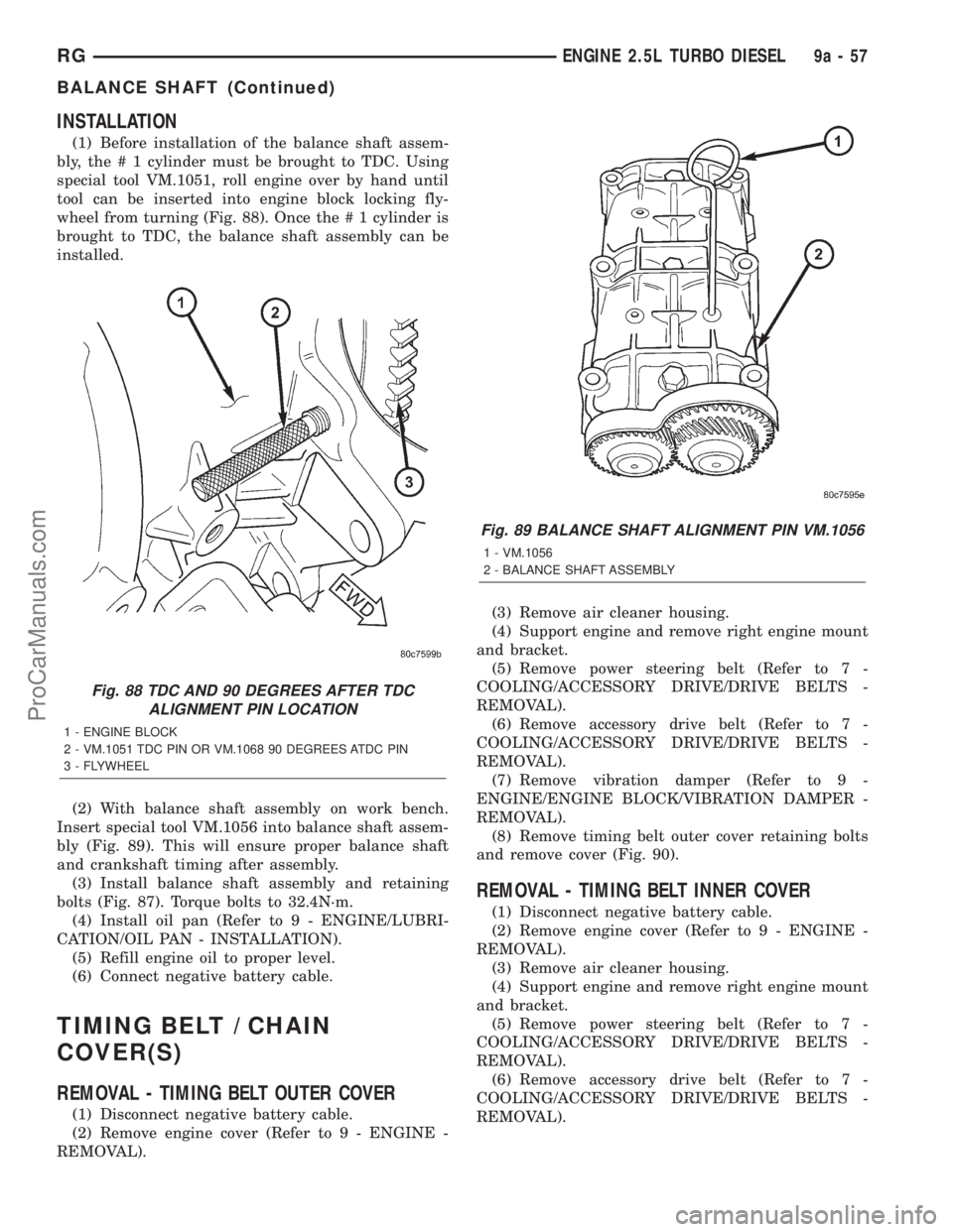
bly, the # 1 cylinder must be brought to TDC. Using
special tool VM.1051, roll engine over by hand until
tool can be inserted into engine block locking fly-
wheel from turning (Fig. 88). Once the # 1 cylinder is
brought to TDC, the balance shaft assembly can be
installed.
(2) With balance shaft assembly on work bench.
Insert special tool VM.1056 into balance shaft assem-
bly (Fig. 89). This will ensure proper balance shaft
and crankshaft timing after assembly.
(3) Install balance shaft assembly and retaining
bolts (Fig. 87). Torque bolts to 32.4N´m.
(4) Install oil pan (Refer to 9 - ENGINE/LUBRI-
CATION/OIL PAN - INSTALLATION).
(5) Refill engine oil to proper level.
(6) Connect negative battery cable.
TIMING BELT / CHAIN
COVER(S)
REMOVAL - TIMING BELT OUTER COVER
(1) Disconnect negative battery cable.
(2) Remove engine cover (Refer to 9 - ENGINE -
REMOVAL).(3) Remove air cleaner housing.
(4) Support engine and remove right engine mount
and bracket.
(5) Remove power steering belt (Refer to 7 -
COOLING/ACCESSORY DRIVE/DRIVE BELTS -
REMOVAL).
(6) Remove accessory drive belt (Refer to 7 -
COOLING/ACCESSORY DRIVE/DRIVE BELTS -
REMOVAL).
(7) Remove vibration damper (Refer to 9 -
ENGINE/ENGINE BLOCK/VIBRATION DAMPER -
REMOVAL).
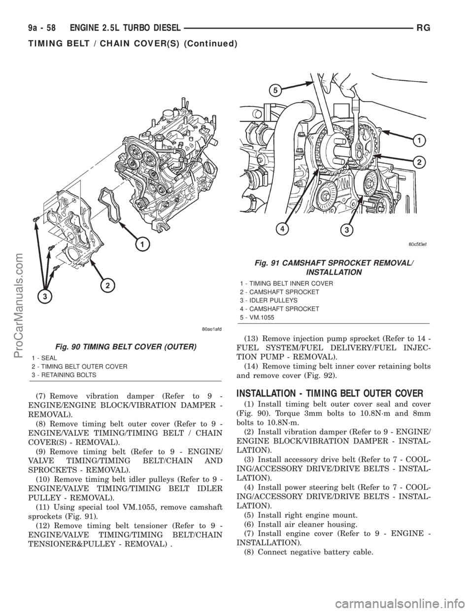
(8) Remove timing belt outer cover retaining bolts
and remove cover (Fig. 90).
REMOVAL - TIMING BELT INNER COVER
(1) Disconnect negative battery cable.
(2) Remove engine cover (Refer to 9 - ENGINE -
REMOVAL).
(3) Remove air cleaner housing.
(4) Support engine and remove right engine mount
and bracket.
(5) Remove power steering belt (Refer to 7 -
COOLING/ACCESSORY DRIVE/DRIVE BELTS -
REMOVAL).
(6) Remove accessory drive belt (Refer to 7 -
COOLING/ACCESSORY DRIVE/DRIVE BELTS -
REMOVAL).
Fig. 88 TDC AND 90 DEGREES AFTER TDC
ALIGNMENT PIN LOCATION
1 - ENGINE BLOCK
2 - VM.1051 TDC PIN OR VM.1068 90 DEGREES ATDC PIN
3 - FLYWHEEL
Fig. 89 BALANCE SHAFT ALIGNMENT PIN VM.1056
1 - VM.1056
2 - BALANCE SHAFT ASSEMBLY
RGENGINE 2.5L TURBO DIESEL9a-57
BALANCE SHAFT (Continued)
ProCarManuals.com
Page 1373 of 2321
(7) Remove vibration damper (Refer to 9 -
ENGINE/ENGINE BLOCK/VIBRATION DAMPER -
REMOVAL).
(8) Remove timing belt outer cover (Refer to 9 -
ENGINE/VALVE TIMING/TIMING BELT / CHAIN
COVER(S) - REMOVAL).
(9) Remove timing belt (Refer to 9 - ENGINE/
VALVE TIMING/TIMING BELT/CHAIN AND
SPROCKETS - REMOVAL).
(10) Remove timing belt idler pulleys (Refer to 9 -
ENGINE/VALVE TIMING/TIMING BELT IDLER
PULLEY - REMOVAL).
(11) Using special tool VM.1055, remove camshaft
sprockets (Fig. 91).
(12) Remove timing belt tensioner (Refer to 9 -
ENGINE/VALVE TIMING/TIMING BELT/CHAIN
TENSIONER&PULLEY - REMOVAL) .(13) Remove injection pump sprocket (Refer to 14 -
FUEL SYSTEM/FUEL DELIVERY/FUEL INJEC-
TION PUMP - REMOVAL).
(14) Remove timing belt inner cover retaining bolts
and remove cover (Fig. 92).INSTALLATION - TIMING BELT OUTER COVER
(1) Install timing belt outer cover seal and cover
(Fig. 90). Torque 3mm bolts to 10.8N´m and 8mm
bolts to 10.8N´m.
(2) Install vibration damper (Refer to 9 - ENGINE/
ENGINE BLOCK/VIBRATION DAMPER - INSTAL-
LATION).
(3) Install accessory drive belt (Refer to 7 - COOL-
ING/ACCESSORY DRIVE/DRIVE BELTS - INSTAL-
LATION).
(4) Install power steering belt (Refer to 7 - COOL-
ING/ACCESSORY DRIVE/DRIVE BELTS - INSTAL-
LATION).
(5) Install right engine mount.
(6) Install air cleaner housing.
(7) Install engine cover (Refer to 9 - ENGINE -
INSTALLATION).
(8) Connect negative battery cable.
Fig. 90 TIMING BELT COVER (OUTER)
1 - SEAL
2 - TIMING BELT OUTER COVER
3 - RETAINING BOLTS
Fig. 91 CAMSHAFT SPROCKET REMOVAL/
INSTALLATION
1 - TIMING BELT INNER COVER
2 - CAMSHAFT SPROCKET
3 - IDLER PULLEYS
4 - CAMSHAFT SPROCKET
5 - VM.1055
9a - 58 ENGINE 2.5L TURBO DIESELRG
TIMING BELT / CHAIN COVER(S) (Continued)
ProCarManuals.com
Page 1374 of 2321
INSTALLATION - TIMING BELT INNER COVER
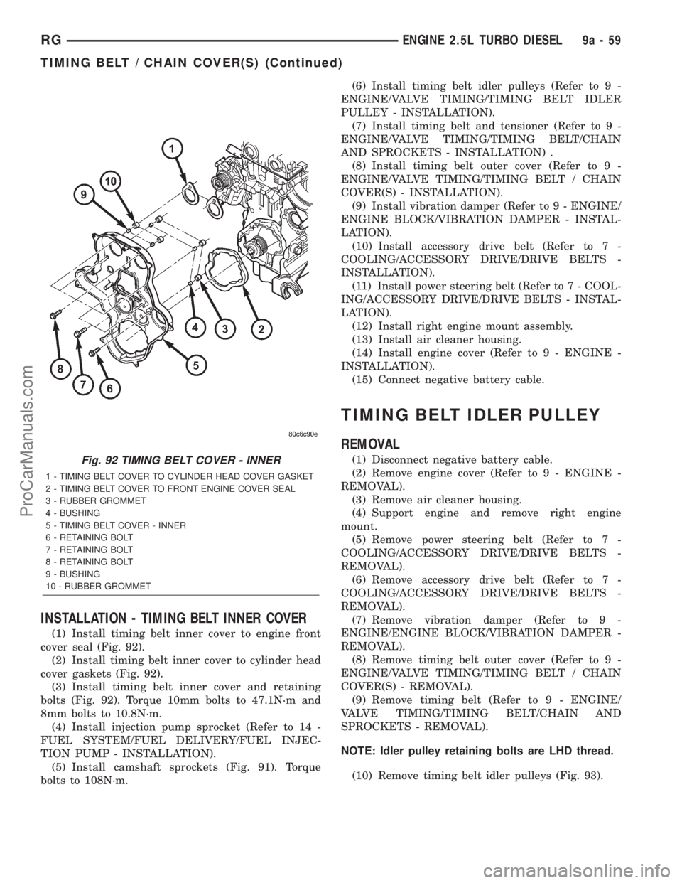
(1) Install timing belt inner cover to engine front
cover seal (Fig. 92).
(2) Install timing belt inner cover to cylinder head
cover gaskets (Fig. 92).
(3) Install timing belt inner cover and retaining
bolts (Fig. 92). Torque 10mm bolts to 47.1N´m and
8mm bolts to 10.8N´m.
(4) Install injection pump sprocket (Refer to 14 -
FUEL SYSTEM/FUEL DELIVERY/FUEL INJEC-
TION PUMP - INSTALLATION).
(5) Install camshaft sprockets (Fig. 91). Torque
bolts to 108N´m.(6) Install timing belt idler pulleys (Refer to 9 -
ENGINE/VALVE TIMING/TIMING BELT IDLER
PULLEY - INSTALLATION).
(7) Install timing belt and tensioner (Refer to 9 -
ENGINE/VALVE TIMING/TIMING BELT/CHAIN
AND SPROCKETS - INSTALLATION) .
(8) Install timing belt outer cover (Refer to 9 -
ENGINE/VALVE TIMING/TIMING BELT / CHAIN
COVER(S) - INSTALLATION).
(9) Install vibration damper (Refer to 9 - ENGINE/
ENGINE BLOCK/VIBRATION DAMPER - INSTAL-
LATION).
(10) Install accessory drive belt (Refer to 7 -
COOLING/ACCESSORY DRIVE/DRIVE BELTS -
INSTALLATION).
(11) Install power steering belt (Refer to 7 - COOL-
ING/ACCESSORY DRIVE/DRIVE BELTS - INSTAL-
LATION).
(12) Install right engine mount assembly.
(13) Install air cleaner housing.
(14) Install engine cover (Refer to 9 - ENGINE -
INSTALLATION).
(15) Connect negative battery cable.
TIMING BELT IDLER PULLEY
REMOVAL
(1) Disconnect negative battery cable.
(2) Remove engine cover (Refer to 9 - ENGINE -
REMOVAL).
(3) Remove air cleaner housing.
(4) Support engine and remove right engine
mount.
(5) Remove power steering belt (Refer to 7 -
COOLING/ACCESSORY DRIVE/DRIVE BELTS -
REMOVAL).
(6) Remove accessory drive belt (Refer to 7 -
COOLING/ACCESSORY DRIVE/DRIVE BELTS -
REMOVAL).
(7) Remove vibration damper (Refer to 9 -
ENGINE/ENGINE BLOCK/VIBRATION DAMPER -
REMOVAL).
(8) Remove timing belt outer cover (Refer to 9 -
ENGINE/VALVE TIMING/TIMING BELT / CHAIN
COVER(S) - REMOVAL).
(9) Remove timing belt (Refer to 9 - ENGINE/
VALVE TIMING/TIMING BELT/CHAIN AND
SPROCKETS - REMOVAL).
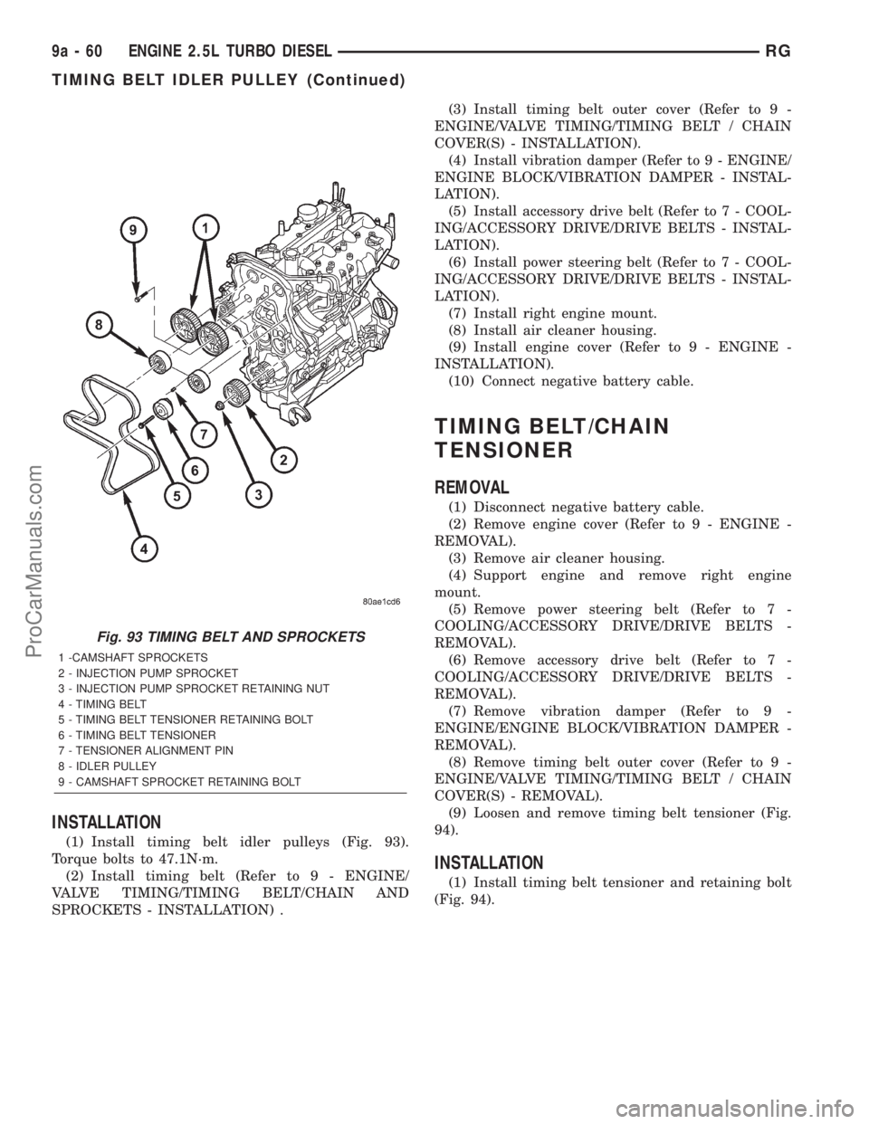
NOTE: Idler pulley retaining bolts are LHD thread.
(10) Remove timing belt idler pulleys (Fig. 93).Fig. 92 TIMING BELT COVER - INNER
1 - TIMING BELT COVER TO CYLINDER HEAD COVER GASKET
2 - TIMING BELT COVER TO FRONT ENGINE COVER SEAL
3 - RUBBER GROMMET
4 - BUSHING
5 - TIMING BELT COVER - INNER
6 - RETAINING BOLT
7 - RETAINING BOLT
8 - RETAINING BOLT
9 - BUSHING
10 - RUBBER GROMMET
RGENGINE 2.5L TURBO DIESEL9a-59
TIMING BELT / CHAIN COVER(S) (Continued)
ProCarManuals.com
Page 1375 of 2321
INSTALLATION
(1) Install timing belt idler pulleys (Fig. 93).
Torque bolts to 47.1N´m.
(2) Install timing belt (Refer to 9 - ENGINE/
VALVE TIMING/TIMING BELT/CHAIN AND
SPROCKETS - INSTALLATION) .(3) Install timing belt outer cover (Refer to 9 -
ENGINE/VALVE TIMING/TIMING BELT / CHAIN
COVER(S) - INSTALLATION).
(4) Install vibration damper (Refer to 9 - ENGINE/
ENGINE BLOCK/VIBRATION DAMPER - INSTAL-
LATION).
(5) Install accessory drive belt (Refer to 7 - COOL-
ING/ACCESSORY DRIVE/DRIVE BELTS - INSTAL-
LATION).
(6) Install power steering belt (Refer to 7 - COOL-
ING/ACCESSORY DRIVE/DRIVE BELTS - INSTAL-
LATION).
(7) Install right engine mount.
(8) Install air cleaner housing.
(9) Install engine cover (Refer to 9 - ENGINE -
INSTALLATION).
(10) Connect negative battery cable.
TIMING BELT/CHAIN
TENSIONER
REMOVAL
(1) Disconnect negative battery cable.
(2) Remove engine cover (Refer to 9 - ENGINE -
REMOVAL).
(3) Remove air cleaner housing.
(4) Support engine and remove right engine
mount.
(5) Remove power steering belt (Refer to 7 -
COOLING/ACCESSORY DRIVE/DRIVE BELTS -
REMOVAL).
(6) Remove accessory drive belt (Refer to 7 -
COOLING/ACCESSORY DRIVE/DRIVE BELTS -
REMOVAL).
(7) Remove vibration damper (Refer to 9 -
ENGINE/ENGINE BLOCK/VIBRATION DAMPER -
REMOVAL).
(8) Remove timing belt outer cover (Refer to 9 -
ENGINE/VALVE TIMING/TIMING BELT / CHAIN
COVER(S) - REMOVAL).
(9) Loosen and remove timing belt tensioner (Fig.
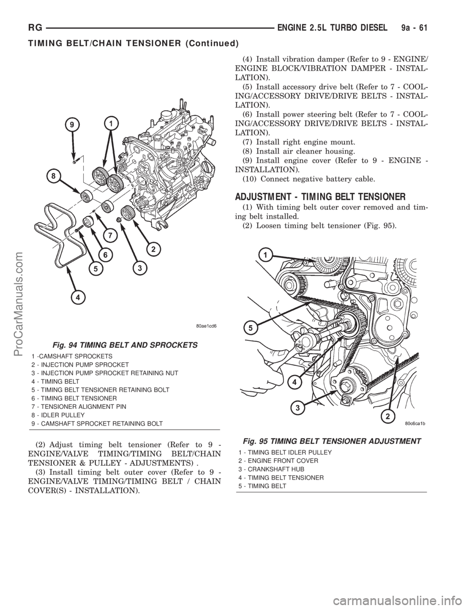
94).
INSTALLATION
(1) Install timing belt tensioner and retaining bolt
(Fig. 94).
Fig. 93 TIMING BELT AND SPROCKETS
1 -CAMSHAFT SPROCKETS
2 - INJECTION PUMP SPROCKET
3 - INJECTION PUMP SPROCKET RETAINING NUT
4 - TIMING BELT
5 - TIMING BELT TENSIONER RETAINING BOLT
6 - TIMING BELT TENSIONER
7 - TENSIONER ALIGNMENT PIN
8 - IDLER PULLEY
9 - CAMSHAFT SPROCKET RETAINING BOLT
9a - 60 ENGINE 2.5L TURBO DIESELRG
TIMING BELT IDLER PULLEY (Continued)
ProCarManuals.com
Page 1376 of 2321
(2) Adjust timing belt tensioner (Refer to 9 -
ENGINE/VALVE TIMING/TIMING BELT/CHAIN
TENSIONER & PULLEY - ADJUSTMENTS) .
(3) Install timing belt outer cover (Refer to 9 -
ENGINE/VALVE TIMING/TIMING BELT / CHAIN
COVER(S) - INSTALLATION).(4) Install vibration damper (Refer to 9 - ENGINE/
ENGINE BLOCK/VIBRATION DAMPER - INSTAL-
LATION).
(5) Install accessory drive belt (Refer to 7 - COOL-
ING/ACCESSORY DRIVE/DRIVE BELTS - INSTAL-
LATION).
(6) Install power steering belt (Refer to 7 - COOL-
ING/ACCESSORY DRIVE/DRIVE BELTS - INSTAL-
LATION).
(7) Install right engine mount.
(8) Install air cleaner housing.
(9) Install engine cover (Refer to 9 - ENGINE -
INSTALLATION).
(10) Connect negative battery cable.
ADJUSTMENT - TIMING BELT TENSIONER
(1) With timing belt outer cover removed and tim-
ing belt installed.
(2) Loosen timing belt tensioner (Fig. 95).
Fig. 94 TIMING BELT AND SPROCKETS
1 -CAMSHAFT SPROCKETS
2 - INJECTION PUMP SPROCKET
3 - INJECTION PUMP SPROCKET RETAINING NUT
4 - TIMING BELT
5 - TIMING BELT TENSIONER RETAINING BOLT
6 - TIMING BELT TENSIONER
7 - TENSIONER ALIGNMENT PIN
8 - IDLER PULLEY
9 - CAMSHAFT SPROCKET RETAINING BOLT
Fig. 95 TIMING BELT TENSIONER ADJUSTMENT
1 - TIMING BELT IDLER PULLEY
2 - ENGINE FRONT COVER
3 - CRANKSHAFT HUB
4 - TIMING BELT TENSIONER
5 - TIMING BELT
RGENGINE 2.5L TURBO DIESEL9a-61
TIMING BELT/CHAIN TENSIONER (Continued)
ProCarManuals.com
Page 1377 of 2321
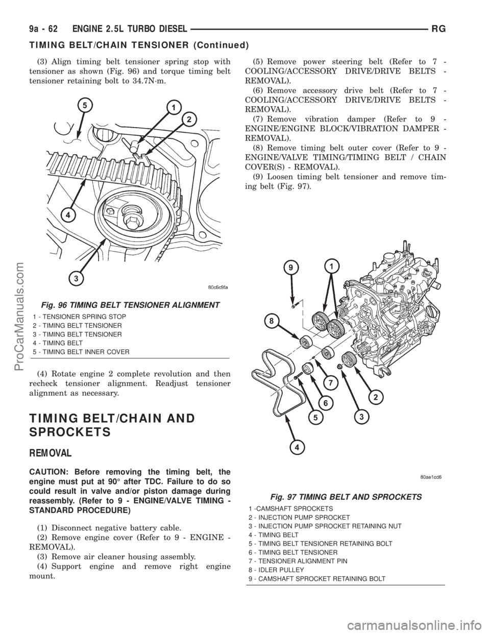
(3) Align timing belt tensioner spring stop with
tensioner as shown (Fig. 96) and torque timing belt
tensioner retaining bolt to 34.7N´m.
(4) Rotate engine 2 complete revolution and then
recheck tensioner alignment. Readjust tensioner
alignment as necessary.
TIMING BELT/CHAIN AND
SPROCKETS
REMOVAL
CAUTION: Before removing the timing belt, the
engine must put at 90É after TDC. Failure to do so
could result in valve and/or piston damage during
reassembly. (Refer to 9 - ENGINE/VALVE TIMING -
STANDARD PROCEDURE)
(1) Disconnect negative battery cable.
(2) Remove engine cover (Refer to 9 - ENGINE -
REMOVAL).
(3) Remove air cleaner housing assembly.
(4) Support engine and remove right engine
mount.(5) Remove power steering belt (Refer to 7 -
COOLING/ACCESSORY DRIVE/DRIVE BELTS -
REMOVAL).
(6) Remove accessory drive belt (Refer to 7 -
COOLING/ACCESSORY DRIVE/DRIVE BELTS -
REMOVAL).
(7) Remove vibration damper (Refer to 9 -
ENGINE/ENGINE BLOCK/VIBRATION DAMPER -
REMOVAL).
(8) Remove timing belt outer cover (Refer to 9 -
ENGINE/VALVE TIMING/TIMING BELT / CHAIN
COVER(S) - REMOVAL).
(9) Loosen timing belt tensioner and remove tim-
ing belt (Fig. 97).
Fig. 96 TIMING BELT TENSIONER ALIGNMENT
1 - TENSIONER SPRING STOP
2 - TIMING BELT TENSIONER
3 - TIMING BELT TENSIONER
4 - TIMING BELT
5 - TIMING BELT INNER COVER
Fig. 97 TIMING BELT AND SPROCKETS
1 -CAMSHAFT SPROCKETS
2 - INJECTION PUMP SPROCKET
3 - INJECTION PUMP SPROCKET RETAINING NUT
4 - TIMING BELT
5 - TIMING BELT TENSIONER RETAINING BOLT
6 - TIMING BELT TENSIONER
7 - TENSIONER ALIGNMENT PIN
8 - IDLER PULLEY
9 - CAMSHAFT SPROCKET RETAINING BOLT
9a - 62 ENGINE 2.5L TURBO DIESELRG
TIMING BELT/CHAIN TENSIONER (Continued)
ProCarManuals.com
Page 1378 of 2321
INSTALLATION
(1) With both camshaft alignment pins still
installed and the engine locked at 90É after TDC.
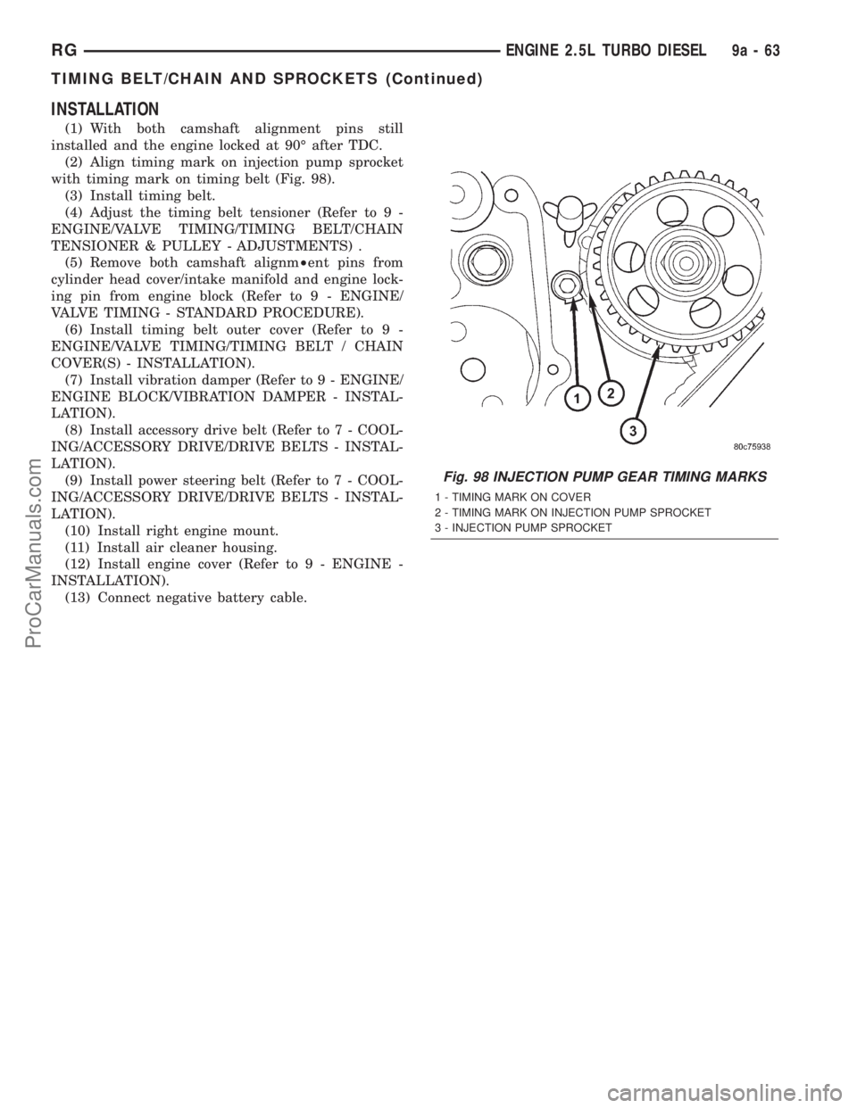
(2) Align timing mark on injection pump sprocket
with timing mark on timing belt (Fig. 98).
(3) Install timing belt.
(4) Adjust the timing belt tensioner (Refer to 9 -
ENGINE/VALVE TIMING/TIMING BELT/CHAIN
TENSIONER & PULLEY - ADJUSTMENTS) .
(5) Remove both camshaft alignm²ent pins from
cylinder head cover/intake manifold and engine lock-
ing pin from engine block (Refer to 9 - ENGINE/
VALVE TIMING - STANDARD PROCEDURE).
(6) Install timing belt outer cover (Refer to 9 -
ENGINE/VALVE TIMING/TIMING BELT / CHAIN
COVER(S) - INSTALLATION).
(7) Install vibration damper (Refer to 9 - ENGINE/
ENGINE BLOCK/VIBRATION DAMPER - INSTAL-
LATION).
(8) Install accessory drive belt (Refer to 7 - COOL-
ING/ACCESSORY DRIVE/DRIVE BELTS - INSTAL-
LATION).
(9) Install power steering belt (Refer to 7 - COOL-
ING/ACCESSORY DRIVE/DRIVE BELTS - INSTAL-
LATION).
(10) Install right engine mount.
(11) Install air cleaner housing.
(12) Install engine cover (Refer to 9 - ENGINE -
INSTALLATION).
(13) Connect negative battery cable.
Fig. 98 INJECTION PUMP GEAR TIMING MARKS
1 - TIMING MARK ON COVER
2 - TIMING MARK ON INJECTION PUMP SPROCKET
3 - INJECTION PUMP SPROCKET
RGENGINE 2.5L TURBO DIESEL9a-63
TIMING BELT/CHAIN AND SPROCKETS (Continued)
ProCarManuals.com
Page 1428 of 2321
ACCELERATOR PEDAL
REMOVAL
(1) Hold the throttle body throttle lever in the
wide open position. Remove the throttle cable from
the throttle body cam.
(2) From inside the vehicle, hold up the pedal and
remove the cable retainer and throttle cable from the
upper end of the pedal shaft.
(3) Remove nuts from accelerator pedal attaching
studs. Remove assembly from vehicle.
INSTALLATION
(1) Position accelerator pedal assembly on dash
panel. Install retaining nuts. Tighten retaining nuts
to 12 N´m (105 in. lbs.) torque.
(2) From inside the vehicle, hold up the pedal and
install the throttle cable and cable retainer in the
upper end of the pedal shaft.
(3) From the engine compartment, hold the throt-
tle body lever in the wide open position and install
the throttle cable.
CRANKSHAFT POSITION
SENSOR
DESCRIPTION
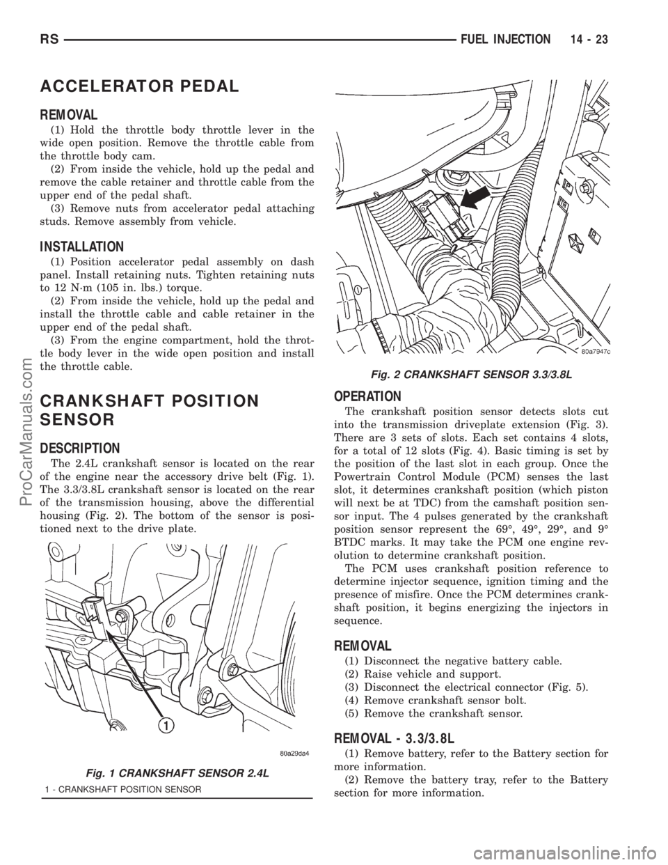
The 2.4L crankshaft sensor is located on the rear
of the engine near the accessory drive belt (Fig. 1).
The 3.3/3.8L crankshaft sensor is located on the rear
of the transmission housing, above the differential
housing (Fig. 2). The bottom of the sensor is posi-
tioned next to the drive plate.
OPERATION
The crankshaft position sensor detects slots cut
into the transmission driveplate extension (Fig. 3).
There are 3 sets of slots. Each set contains 4 slots,
for a total of 12 slots (Fig. 4). Basic timing is set by
the position of the last slot in each group. Once the
Powertrain Control Module (PCM) senses the last
slot, it determines crankshaft position (which piston
will next be at TDC) from the camshaft position sen-
sor input. The 4 pulses generated by the crankshaft
position sensor represent the 69É, 49É, 29É, and 9É
BTDC marks. It may take the PCM one engine rev-
olution to determine crankshaft position.
The PCM uses crankshaft position reference to
determine injector sequence, ignition timing and the
presence of misfire. Once the PCM determines crank-
shaft position, it begins energizing the injectors in
sequence.
REMOVAL
(1) Disconnect the negative battery cable.
(2) Raise vehicle and support.
(3) Disconnect the electrical connector (Fig. 5).
(4) Remove crankshaft sensor bolt.
(5) Remove the crankshaft sensor.
REMOVAL - 3.3/3.8L
(1) Remove battery, refer to the Battery section for
more information.
(2) Remove the battery tray, refer to the Battery
section for more information.
Fig. 1 CRANKSHAFT SENSOR 2.4L
1 - CRANKSHAFT POSITION SENSOR
Fig. 2 CRANKSHAFT SENSOR 3.3/3.8L
RSFUEL INJECTION14-23
ProCarManuals.com
Page 1447 of 2321
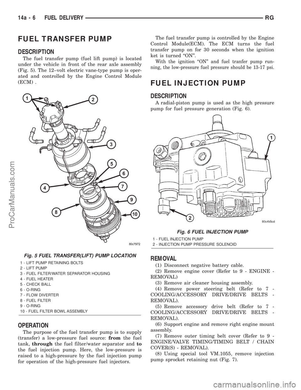
FUEL TRANSFER PUMP
DESCRIPTION
The fuel transfer pump (fuel lift pump) is located
under the vehicle in front of the rear axle assembly
(Fig. 5). The 12±volt electric vane-type pump is oper-
ated and controlled by the Engine Control Module
(ECM) .
OPERATION
The purpose of the fuel transfer pump is to supply
(transfer) a low-pressure fuel source:fromthe fuel
tank,throughthe fuel filter/water separator andto
the fuel injection pump. Here, the low-pressure is
raised to a high-pressure by the fuel injection pump
for operation of the high-pressure fuel injectors.The fuel transfer pump is controlled by the Engine
Control Module(ECM). The ECM turns the fuel
transfer pump on for 30 seconds when the ignition
ket is turned ªONº.
With the ignition ªONº and fuel tranfer pump run-
ning, the low-pressure fuel pressure should be 13-17 psi.
FUEL INJECTION PUMP
DESCRIPTION
A radial-piston pump is used as the high pressure
pump for fuel pressure generation (Fig. 6).
REMOVAL
(1) Disconnect negative battery cable.
(2) Remove engine cover (Refer to 9 - ENGINE -
REMOVAL)
(3) Remove air cleaner housing assembly.
(4) Remove power steering belt (Refer to 7 -
COOLING/ACCESSORY DRIVE/DRIVE BELTS -
REMOVAL).
(5) Remove accessory drive belt (Refer to 7 -
COOLING/ACCESSORY DRIVE/DRIVE BELTS -
REMOVAL).
(6) Support engine and remove right engine mount
assembly.
(7) Remove outer timing belt cover (Refer to 9 -
ENGINE/VALVE TIMING/TIMING BELT / CHAIN
COVER(S) - REMOVAL).
(8) Using special tool VM.1055, remove injection
pump sprocket retaining nut (Fig. 7).
Fig. 5 FUEL TRANSFER(LIFT) PUMP LOCATION
1 - LIFT PUMP RETAINING BOLTS
2 - LIFT PUMP
3 - FUEL FILTER/WATER SEPARATOR HOUSING
4 - FUEL HEATER
5 - CHECK BALL
6 - O-RING
7 - FLOW DIVERTER
8 - FUEL FILTER
9 - O-RING
10 - FUEL FILTER BOWL ASSEMBLY
Fig. 6 FUEL INJECTION PUMP
1 - FUEL INJECTION PUMP
2 - INJECTION PUMP PRESSURE SOLENOID
14a - 6 FUEL DELIVERYRG
ProCarManuals.com
Page 1448 of 2321
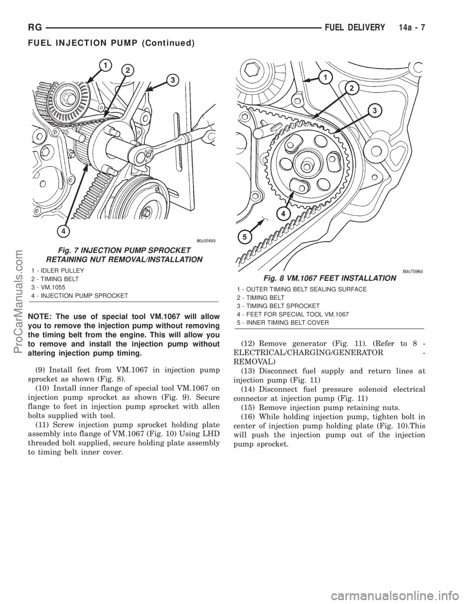
NOTE: The use of special tool VM.1067 will allow
you to remove the injection pump without removing
the timing belt from the engine. This will allow you
to remove and install the injection pump without
altering injection pump timing.
(9) Install feet from VM.1067 in injection pump
sprocket as shown (Fig. 8).
(10) Install inner flange of special tool VM.1067 on
injection pump sprocket as shown (Fig. 9). Secure
flange to feet in injection pump sprocket with allen
bolts supplied with tool.
(11) Screw injection pump sprocket holding plate
assembly into flange of VM.1067 (Fig. 10) Using LHD
threaded bolt supplied, secure holding plate assembly
to timing belt inner cover.(12) Remove generator (Fig. 11). (Refer to 8 -
ELECTRICAL/CHARGING/GENERATOR -
REMOVAL)
(13) Disconnect fuel supply and return lines at
injection pump (Fig. 11)
(14) Disconnect fuel pressure solenoid electrical
connector at injection pump (Fig. 11)
(15) Remove injection pump retaining nuts.
(16) While holding injection pump, tighten bolt in
center of injection pump holding plate (Fig. 10).This
will push the injection pump out of the injection
pump sprocket.
Fig. 7 INJECTION PUMP SPROCKET
RETAINING NUT REMOVAL/INSTALLATION
1 - IDLER PULLEY
2 - TIMING BELT
3 - VM.1055
4 - INJECTION PUMP SPROCKET
Fig. 8 VM.1067 FEET INSTALLATION
1 - OUTER TIMING BELT SEALING SURFACE
2 - TIMING BELT
3 - TIMING BELT SPROCKET
4 - FEET FOR SPECIAL TOOL VM.1067
5 - INNER TIMING BELT COVER
RGFUEL DELIVERY14a-7
FUEL INJECTION PUMP (Continued)
ProCarManuals.com