belt DODGE TOWN AND COUNTRY 2001 Service Manual
[x] Cancel search | Manufacturer: DODGE, Model Year: 2001, Model line: TOWN AND COUNTRY, Model: DODGE TOWN AND COUNTRY 2001Pages: 2321, PDF Size: 68.09 MB
Page 1449 of 2321
INSTALLATION
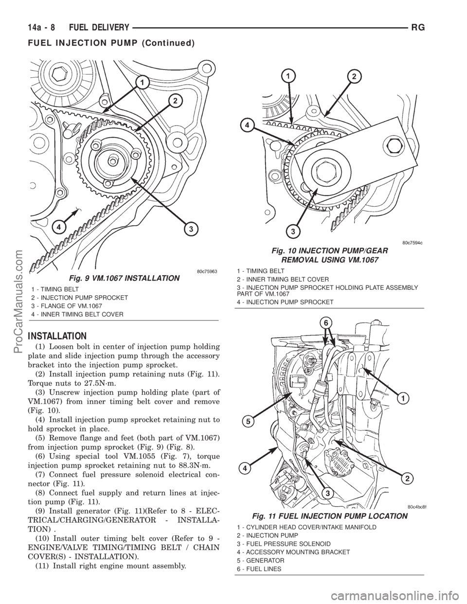
(1) Loosen bolt in center of injection pump holding
plate and slide injection pump through the accessory
bracket into the injection pump sprocket.
(2) Install injection pump retaining nuts (Fig. 11).
Torque nuts to 27.5N´m.
(3) Unscrew injection pump holding plate (part of
VM.1067) from inner timing belt cover and remove
(Fig. 10).
(4) Install injection pump sprocket retaining nut to
hold sprocket in place.
(5) Remove flange and feet (both part of VM.1067)
from injection pump sprocket (Fig. 9) (Fig. 8).
(6) Using special tool VM.1055 (Fig. 7), torque
injection pump sprocket retaining nut to 88.3N´m.
(7) Connect fuel pressure solenoid electrical con-
nector (Fig. 11).
(8) Connect fuel supply and return lines at injec-
tion pump (Fig. 11).
(9) Install generator (Fig. 11)(Refer to 8 - ELEC-
TRICAL/CHARGING/GENERATOR - INSTALLA-
TION) .
(10) Install outer timing belt cover (Refer to 9 -
ENGINE/VALVE TIMING/TIMING BELT / CHAIN
COVER(S) - INSTALLATION).
(11) Install right engine mount assembly.
Fig. 9 VM.1067 INSTALLATION
1 - TIMING BELT
2 - INJECTION PUMP SPROCKET
3 - FLANGE OF VM.1067
4 - INNER TIMING BELT COVER
Fig. 10 INJECTION PUMP/GEAR
REMOVAL USING VM.1067
1 - TIMING BELT
2 - INNER TIMING BELT COVER
3 - INJECTION PUMP SPROCKET HOLDING PLATE ASSEMBLY
PART OF VM.1067
4 - INJECTION PUMP SPROCKET
Fig. 11 FUEL INJECTION PUMP LOCATION
1 - CYLINDER HEAD COVER/INTAKE MANIFOLD
2 - INJECTION PUMP
3 - FUEL PRESSURE SOLENOID
4 - ACCESSORY MOUNTING BRACKET
5 - GENERATOR
6 - FUEL LINES
14a - 8 FUEL DELIVERYRG
FUEL INJECTION PUMP (Continued)
ProCarManuals.com
Page 1450 of 2321
(12) Install accessory drive belt (Refer to 7 -
COOLING/ACCESSORY DRIVE/DRIVE BELTS -
INSTALLATION).
(13) Install power steering belt (Refer to 7 -
COOLING/ACCESSORY DRIVE/DRIVE BELTS -
INSTALLATION).
(14) Install air cleaner housing assembly.
(15) Install engine cover (Refer to 9 - ENGINE -
INSTALLATION).
(16) Connect negative battery cable.
WATER IN FUEL SENSOR
DESCRIPTION
The WIF sensor is located in the bowl assembly of
the fuel filter/water separator.
OPERATION
The sensor sends an input to the Engine Control
Module (ECM) when it senses water in the fuel filter/
water separator. As the water level in the filter/sep-
arator increases, the resistance across the WIF
sensor decreases. This decrease in resistance is sent
as a signal to the ECM and compared to a high
water standard value. Once the value reaches 30 to
40 kilohms, the ECM will activate the water-in-fuel
warning lamp through CCD bus circuits. This all
takes place when the ignition key is initially put in
the ON position. The ECM continues to monitor the
input at the end of the intake manifold air heater
post-heat cycle.
RGFUEL DELIVERY14a-9
FUEL INJECTION PUMP (Continued)
ProCarManuals.com
Page 1453 of 2321
INSTALLATION
NOTE: Be sure the copper washer is installed on
end of injector before installing in cylinder head.
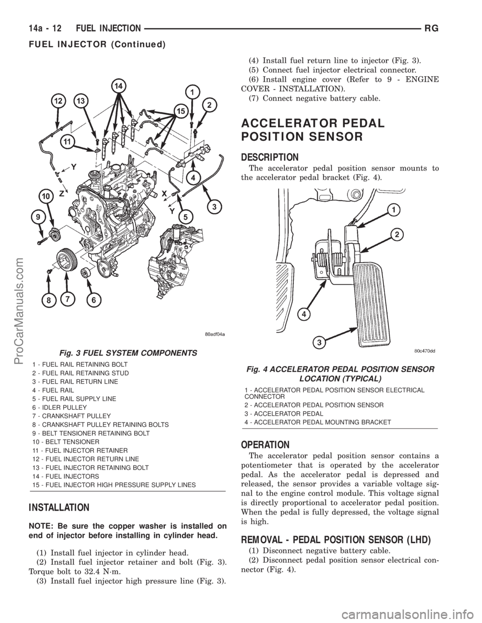
(1) Install fuel injector in cylinder head.
(2) Install fuel injector retainer and bolt (Fig. 3).
Torque bolt to 32.4 N´m.
(3) Install fuel injector high pressure line (Fig. 3).(4) Install fuel return line to injector (Fig. 3).
(5) Connect fuel injector electrical connector.
(6) Install engine cover (Refer to 9 - ENGINE
COVER - INSTALLATION).
(7) Connect negative battery cable.
ACCELERATOR PEDAL
POSITION SENSOR
DESCRIPTION
The accelerator pedal position sensor mounts to
the accelerator pedal bracket (Fig. 4).
OPERATION
The accelerator pedal position sensor contains a
potentiometer that is operated by the accelerator
pedal. As the accelerator pedal is depressed and
released, the sensor provides a variable voltage sig-
nal to the engine control module. This voltage signal
is directly proportional to accelerator pedal position.
When the pedal is fully depressed, the voltage signal
is high.
REMOVAL - PEDAL POSITION SENSOR (LHD)
(1) Disconnect negative battery cable.
(2) Disconnect pedal position sensor electrical con-
nector (Fig. 4).
Fig. 3 FUEL SYSTEM COMPONENTS
1 - FUEL RAIL RETAINING BOLT
2 - FUEL RAIL RETAINING STUD
3 - FUEL RAIL RETURN LINE
4 - FUEL RAIL
5 - FUEL RAIL SUPPLY LINE
6 - IDLER PULLEY
7 - CRANKSHAFT PULLEY
8 - CRANKSHAFT PULLEY RETAINING BOLTS
9 - BELT TENSIONER RETAINING BOLT
10 - BELT TENSIONER
11 - FUEL INJECTOR RETAINER
12 - FUEL INJECTOR RETURN LINE
13 - FUEL INJECTOR RETAINING BOLT
14 - FUEL INJECTORS
15 - FUEL INJECTOR HIGH PRESSURE SUPPLY LINESFig. 4 ACCELERATOR PEDAL POSITION SENSOR
LOCATION (TYPICAL)
1 - ACCELERATOR PEDAL POSITION SENSOR ELECTRICAL
CONNECTOR
2 - ACCELERATOR PEDAL POSITION SENSOR
3 - ACCELERATOR PEDAL
4 - ACCELERATOR PEDAL MOUNTING BRACKET
14a - 12 FUEL INJECTIONRG
FUEL INJECTOR (Continued)
ProCarManuals.com
Page 1458 of 2321
STEERING
TABLE OF CONTENTS
page page
STEERING
DESCRIPTION............................1
OPERATION.............................1
DIAGNOSIS AND TESTING..................1
POWER STEERING SYSTEM FLOW AND
PRESSURE TEST........................1STEERING SYSTEM DIAGNOSIS CHARTS....3
SPECIFICATIONS.........................9
SPECIAL TOOLS..........................9
COLUMN...............................10
GEAR.................................17
PUMP.................................24
STEERING
DESCRIPTION - POWER STEERING SYSTEM
This vehicle comes with power steering as stan-
dard equipment and it is the only steering system
available. The power steering system consists of
these major components:
²POWER STEERING PUMP
²POWER STEERING GEAR
²POWER STEERING FLUID RESERVOIR
²POWER STEERING FLUID SUPPLY HOSE
²POWER STEERING FLUID PRESSURE HOSE
²POWER STEERING FLUID RETURN HOSE
²POWER STEERING FLUID COOLER
For information on the first two components, refer
to their respective sections within this service man-
ual group. Information on all other components can
be found in POWER STEERING PUMP.
OPERATION - POWER STEERING SYSTEM
Turning of the steering wheel is converted into linear
(side-to-side) travel through the meshing of the helical
pinion teeth with the rack teeth within the steering
gear. The lateral travel pushes and pulls the tie rods to
change the direction of the vehicle's front wheels.
Power assist steering is provided by a belt driven
rotary type pump. It directs fluid through power
steering fluid hoses to the power steering gear where
it is used to assist the driver's turning effort.
Manual steering control of the vehicle can be main-
tained if power steering assist is lost. However, under
this condition, steering effort is significantly increased.
DIAGNOSIS AND TESTING - POWER STEERING
SYSTEM FLOW AND PRESSURE TEST
ALL ENGINES
The following procedure is to be used to test the
operation of the power steering system on this vehi-
cle. This test will provide the flow rate of the power
steering pump along with the maximum relief pres-sure. This test is to be performed any time a power
steering system problem is present to determine if
the power steering pump or power steering gear is
not functioning properly. The following flow and pres-
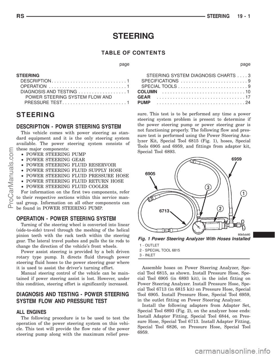
sure test is performed using the Power Steering Ana-
lyzer Kit, Special Tool 6815 (Fig. 1), hoses, Special
Tools 6905 and 6959, and fittings from adapter kit,
Special Tool 6893.
Assemble hoses on Power Steering Analyzer, Spe-
cial Tool 6815, as shown. Install Pressure Hose, Spe-
cial Tool 6905 (in 6893 kit), in the inlet fitting on
Power Steering Analyzer. Install Pressure Hose, Spe-
cial Tool 6713 (in 6815 kit) on Pressure Hose, Special
Tool 6905. Install Pressure Hose, Special Tool 6959,
in the outlet fitting on Power Steering Analyzer.
Install the following adapters from Adapter Set,
Special Tool 6893 (Fig. 2), on the analyzer hose ends:
Install Adapter Fitting, Special Tool 6844, on Pres-
sure Hose, Special Tool 6713. Install Adapter Fitting,
Special Tool 6826, on Pressure Hose, Special Tool
6959.
Fig. 1 Power Steering Analyzer With Hoses Installed
1 - OUTLET
2 - SPECIAL TOOL 6815
3 - INLET
RSSTEERING19-1
ProCarManuals.com
Page 1459 of 2321
CAUTION: To prevent personal injury, safety gog-
gles should be worn at all times when performing
any test procedures on the power steering pump or
power steering gear.
The following procedure is to be used to test the
operation of the power steering system on the vehi-
cle.
(1) Check belt tension and adjust as necessary.
(2) Disconnect the power steering fluid pressure
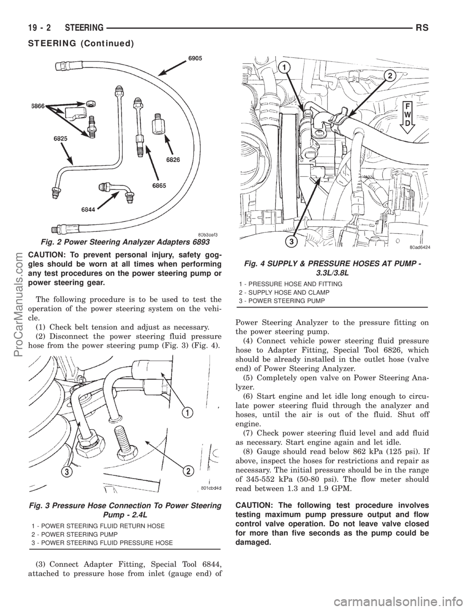
hose from the power steering pump (Fig. 3) (Fig. 4).
(3) Connect Adapter Fitting, Special Tool 6844,
attached to pressure hose from inlet (gauge end) ofPower Steering Analyzer to the pressure fitting on
the power steering pump.
(4) Connect vehicle power steering fluid pressure
hose to Adapter Fitting, Special Tool 6826, which
should be already installed in the outlet hose (valve
end) of Power Steering Analyzer.
(5) Completely open valve on Power Steering Ana-
lyzer.
(6) Start engine and let idle long enough to circu-
late power steering fluid through the analyzer and
hoses, until the air is out of the fluid. Shut off
engine.
(7) Check power steering fluid level and add fluid
as necessary. Start engine again and let idle.
(8) Gauge should read below 862 kPa (125 psi). If
above, inspect the hoses for restrictions and repair as
necessary. The initial pressure should be in the range
of 345-552 kPa (50-80 psi). The flow meter should
read between 1.3 and 1.9 GPM.
CAUTION: The following test procedure involves
testing maximum pump pressure output and flow
control valve operation. Do not leave valve closed
for more than five seconds as the pump could be
damaged.
Fig. 2 Power Steering Analyzer Adapters 6893
Fig. 3 Pressure Hose Connection To Power Steering
Pump - 2.4L
1 - POWER STEERING FLUID RETURN HOSE
2 - POWER STEERING PUMP
3 - POWER STEERING FLUID PRESSURE HOSE
Fig. 4 SUPPLY & PRESSURE HOSES AT PUMP -
3.3L/3.8L
1 - PRESSURE HOSE AND FITTING
2 - SUPPLY HOSE AND CLAMP
3 - POWER STEERING PUMP
19 - 2 STEERINGRS
STEERING (Continued)
ProCarManuals.com
Page 1461 of 2321
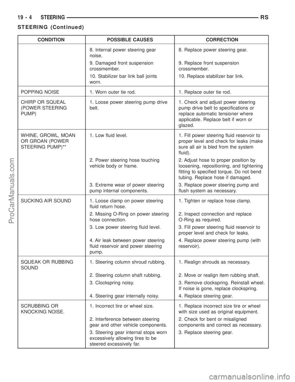
CONDITION POSSIBLE CAUSES CORRECTION
8. Internal power steering gear
noise.8. Replace power steering gear.
9. Damaged front suspension
crossmember.9. Replace front suspension
crossmember.
10. Stabilizer bar link ball joints
worn.10. Replace stabilizer bar link.
POPPING NOISE 1. Worn outer tie rod. 1. Replace outer tie rod.
CHIRP OR SQUEAL
(POWER STEERING
PUMP)1. Loose power steering pump drive
belt.1. Check and adjust power steering
pump drive belt to specifications or
replace automatic tensioner where
applicable. Replace belt if worn or
glazed.
WHINE, GROWL, MOAN
OR GROAN (POWER
STEERING PUMP)**1. Low fluid level. 1. Fill power steering fluid reservoir to
proper level and check for leaks (make
sure all air is bled from the system
fluid).
2. Power steering hose touching
vehicle body or frame.2. Adjust hose to proper position by
loosening, repositioning, and tightening
fitting to specified torque. Do not bend
tubing. Replace hose if damaged.
3. Extreme wear of power steering
pump internal components.3. Replace power steering pump and
flush system as necessary.
SUCKING AIR SOUND 1. Loose clamp on power steering
fluid return hose.1. Tighten or replace hose clamp.
2. Missing O-Ring on power steering
hose connection.2. Inspect connection and replace
O-Ring as required.
3. Low power steering fluid level. 3. Fill power steering fluid reservoir to
proper level and check for leaks.
4. Air leak between power steering
fluid reservoir and power steering
pump.4. Replace power steering pump (with
reservoir).
SQUEAK OR RUBBING
SOUND1. Steering column shroud rubbing. 1. Realign shrouds as necessary.
2. Steering column shaft rubbing. 2. Move or realign item rubbing shaft.
3. Clockspring noisy. 3. Remove clockspring. Reinstall wheel.
If noise is gone, replace clockspring.
4. Steering gear internally noisy. 4. Replace steering gear.
SCRUBBING OR
KNOCKING NOISE.1. Incorrect tire or wheel size. 1. Replace incorrect size tire or wheel
with size used as original equipment.
2. Interference between steering
gear and other vehicle components.2. Check for bent or misaligned
components and correct as necessary.
3. Steering gear internal stops worn
excessively allowing tires to be
steered excessively far.3. Replace steering gear.
19 - 4 STEERINGRS
STEERING (Continued)
ProCarManuals.com
Page 1463 of 2321
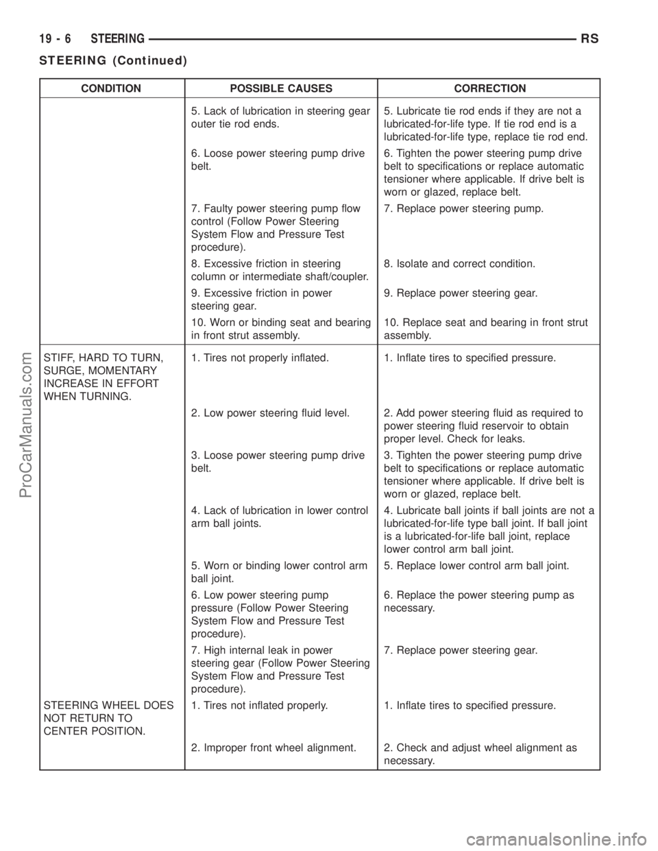
CONDITION POSSIBLE CAUSES CORRECTION
5. Lack of lubrication in steering gear
outer tie rod ends.5. Lubricate tie rod ends if they are not a
lubricated-for-life type. If tie rod end is a
lubricated-for-life type, replace tie rod end.
6. Loose power steering pump drive
belt.6. Tighten the power steering pump drive
belt to specifications or replace automatic
tensioner where applicable. If drive belt is
worn or glazed, replace belt.
7. Faulty power steering pump flow
control (Follow Power Steering
System Flow and Pressure Test
procedure).7. Replace power steering pump.
8. Excessive friction in steering
column or intermediate shaft/coupler.8. Isolate and correct condition.
9. Excessive friction in power
steering gear.9. Replace power steering gear.
10. Worn or binding seat and bearing
in front strut assembly.10. Replace seat and bearing in front strut
assembly.
STIFF, HARD TO TURN,
SURGE, MOMENTARY
INCREASE IN EFFORT
WHEN TURNING.1. Tires not properly inflated. 1. Inflate tires to specified pressure.
2. Low power steering fluid level. 2. Add power steering fluid as required to
power steering fluid reservoir to obtain
proper level. Check for leaks.
3. Loose power steering pump drive
belt.3. Tighten the power steering pump drive
belt to specifications or replace automatic
tensioner where applicable. If drive belt is
worn or glazed, replace belt.
4. Lack of lubrication in lower control
arm ball joints.4. Lubricate ball joints if ball joints are not a
lubricated-for-life type ball joint. If ball joint
is a lubricated-for-life ball joint, replace
lower control arm ball joint.
5. Worn or binding lower control arm
ball joint.5. Replace lower control arm ball joint.
6. Low power steering pump
pressure (Follow Power Steering
System Flow and Pressure Test
procedure).6. Replace the power steering pump as
necessary.
7. High internal leak in power
steering gear (Follow Power Steering
System Flow and Pressure Test
procedure).7. Replace power steering gear.
STEERING WHEEL DOES
NOT RETURN TO
CENTER POSITION.1. Tires not inflated properly. 1. Inflate tires to specified pressure.
2. Improper front wheel alignment. 2. Check and adjust wheel alignment as
necessary.
19 - 6 STEERINGRS
STEERING (Continued)
ProCarManuals.com
Page 1481 of 2321
PUMP
TABLE OF CONTENTS
page page
PUMP
DESCRIPTION...........................24
OPERATION.............................24
CAUTION...............................25
STANDARD PROCEDURE..................25
POWER STEERING PUMP INITIAL
OPERATION...........................25
REMOVAL..............................25
DISASSEMBLY...........................28
ASSEMBLY.............................28
INSTALLATION...........................29SPECIAL TOOLS.........................30
FLUID
STANDARD PROCEDURE..................30
POWER STEERING FLUID LEVEL
CHECKING............................30
FLUID COOLER
DESCRIPTION...........................30
OPERATION.............................30
REMOVAL..............................31
INSTALLATION...........................31
PUMP
DESCRIPTION
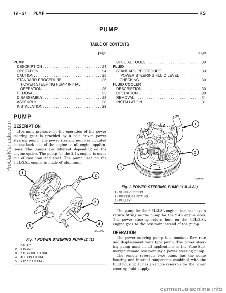
Hydraulic pressure for the operation of the power
steering gear is provided by a belt driven power
steering pump. The power steering pump is mounted
on the back side of the engine on all engine applica-
tions. The pumps are different depending on the
engine option. The pump for the 2.4L engine is made
out of cast iron and steel. The pump used on the
3.3L/3.8L engine is made of aluminum.
The pump for the 3.3L/3.8L engine does not have a
return fitting as the pump for the 2.4L engine does.
The power steering return hose on the 3.3L/3.8L
engine goes to the reservoir instead of the pump.
OPERATION
The power steering pump is a constant flow rate
and displacement vane type pump. The power steer-
ing pump used on all applications is the Vane-Sub-
merged remote reservoir style power steering pump.
The remote reservoir type pump has the pump
housing and internal components combined with the
fluid housing. It has a remote reservoir for the power
steering fluid supply.Fig. 1 POWER STEERING PUMP (2.4L)
1 - PULLEY
2 - BRACKET
3 - PRESSURE FITTING
4 - RETURN FITTING
5 - SUPPLY FITTING
Fig. 2 POWER STEERING PUMP (3.3L/3.8L)
1 - SUPPLY FITTING
2 - PRESSURE FITTING
3 - PULLEY
19 - 24 PUMPRS
ProCarManuals.com
Page 1483 of 2321
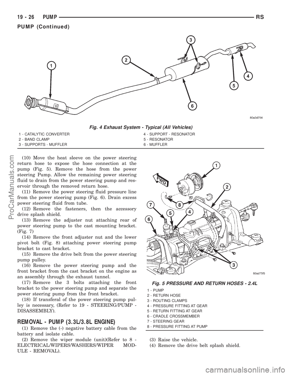
(10) Move the heat sleeve on the power steering
return hose to expose the hose connection at the
pump (Fig. 5). Remove the hose from the power
steering Pump. Allow the remaining power steering
fluid to drain from the power steering pump and res-
ervoir through the removed return hose.
(11) Remove the power steering fluid pressure line
from the power steering pump (Fig. 6). Drain excess
power steering fluid from tube.
(12) Remove the fasteners, then the accessory
drive splash shield.
(13) Remove the adjuster nut attaching rear of
power steering pump to the cast mounting bracket.
(Fig. 7)
(14) Remove the front adjuster nut and the lower
pivot bolt (Fig. 8) attaching power steering pump
bracket to cast bracket.
(15) Remove the drive belt from the power steering
pump pulley.
(16) Remove the power steering pump and the
front bracket from the cast bracket on the engine as
an assembly through the exhaust tunnel.
(17) Remove the 3 bolts attaching the front
bracket to the power steering pump and separate the
power steering pump from the front bracket.
(18) If transferal of the power steering pump pul-
ley is necessary, (Refer to 19 - STEERING/PUMP -
DISASSEMBLY).
REMOVAL - PUMP (3.3L/3.8L ENGINE)
(1) Remove the (-) negative battery cable from the
battery and isolate cable.
(2) Remove the wiper module (unit)(Refer to 8 -
ELECTRICAL/WIPERS/WASHERS/WIPER MOD-
ULE - REMOVAL).(3) Raise the vehicle.
(4) Remove the drive belt splash shield.
Fig. 4 Exhaust System - Typical (All Vehicles)
1 - CATALYTIC CONVERTER 4 - SUPPORT - RESONATOR
2 - BAND CLAMP 5 - RESONATOR
3 - SUPPORTS - MUFFLER 6 - MUFFLER
Fig. 5 PRESSURE AND RETURN HOSES - 2.4L
1 - PUMP
2 - RETURN HOSE
3 - ROUTING CLAMPS
4 - PRESSURE FITTING AT GEAR
5 - RETURN FITTING AT GEAR
6 - CRADLE CROSSMEMBER
7 - STEERING GEAR
8 - PRESSURE FITTING AT PUMP
19 - 26 PUMPRS
PUMP (Continued)
ProCarManuals.com
Page 1484 of 2321
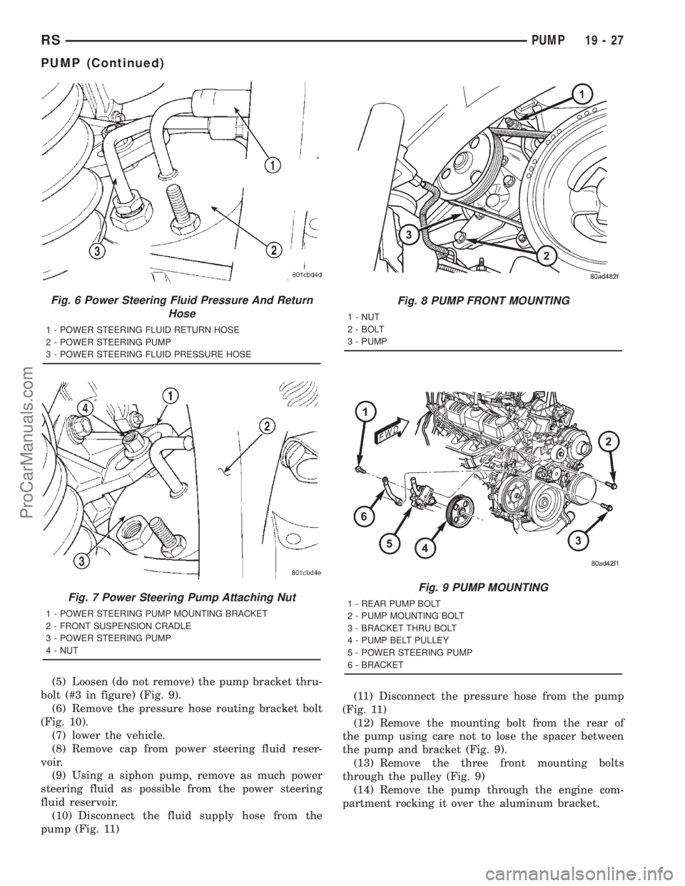
(5) Loosen (do not remove) the pump bracket thru-
bolt (#3 in figure) (Fig. 9).
(6) Remove the pressure hose routing bracket bolt
(Fig. 10).
(7) lower the vehicle.
(8) Remove cap from power steering fluid reser-
voir.
(9) Using a siphon pump, remove as much power
steering fluid as possible from the power steering
fluid reservoir.
(10) Disconnect the fluid supply hose from the
pump (Fig. 11)(11) Disconnect the pressure hose from the pump
(Fig. 11)
(12) Remove the mounting bolt from the rear of
the pump using care not to lose the spacer between
the pump and bracket (Fig. 9).
(13) Remove the three front mounting bolts
through the pulley (Fig. 9)
(14) Remove the pump through the engine com-
partment rocking it over the aluminum bracket.
Fig. 6 Power Steering Fluid Pressure And Return
Hose
1 - POWER STEERING FLUID RETURN HOSE
2 - POWER STEERING PUMP
3 - POWER STEERING FLUID PRESSURE HOSE
Fig. 7 Power Steering Pump Attaching Nut
1 - POWER STEERING PUMP MOUNTING BRACKET
2 - FRONT SUSPENSION CRADLE
3 - POWER STEERING PUMP
4 - NUT
Fig. 8 PUMP FRONT MOUNTING
1 - NUT
2 - BOLT
3 - PUMP
Fig. 9 PUMP MOUNTING
1 - REAR PUMP BOLT
2 - PUMP MOUNTING BOLT
3 - BRACKET THRU BOLT
4 - PUMP BELT PULLEY
5 - POWER STEERING PUMP
6 - BRACKET
RSPUMP19-27
PUMP (Continued)
ProCarManuals.com