automatic transmission DODGE TOWN AND COUNTRY 2001 User Guide
[x] Cancel search | Manufacturer: DODGE, Model Year: 2001, Model line: TOWN AND COUNTRY, Model: DODGE TOWN AND COUNTRY 2001Pages: 2321, PDF Size: 68.09 MB
Page 135 of 2321
REAR DRIVELINE MODULE
TABLE OF CONTENTS
page page
REAR DRIVELINE MODULE
DESCRIPTION...........................26
OPERATION.............................26
DIAGNOSIS AND TESTING.................27
REAR DRIVELINE MODULE NOISE.........27
REAR DRIVELINE MODULE OPERATION....29
REMOVAL..............................29
DISASSEMBLY...........................30
ASSEMBLY.............................32
INSTALLATION...........................36
SPECIFICATIONS........................37
SPECIAL TOOLS.........................37
BI-DIRECTIONAL OVERRUNNING CLUTCH
DESCRIPTION...........................37
OPERATION.............................38
DIFFERENTIAL ASSEMBLY
DESCRIPTION...........................43
OPERATION.............................43FLUID - DIFFERENTIAL ASSEMBLY
STANDARD PROCEDURE..................44
DIFFERENTIAL ASSEMBLY FLUID CHANGE . . 44
FLUID
STANDARD PROCEDURE..................44
OVERRUNNING CLUTCH HOUSING FLUID
CHANGE..............................44
VISCOUS COUPLER
DESCRIPTION...........................45
OPERATION.............................45
TORQUE ARM
REMOVAL..............................47
INSTALLATION...........................47
INPUT FLANGE SEAL
REMOVAL..............................47
INSTALLATION...........................47
OUTPUT FLANGE SEAL
REMOVAL..............................49
INSTALLATION...........................50
REAR DRIVELINE MODULE
DESCRIPTION
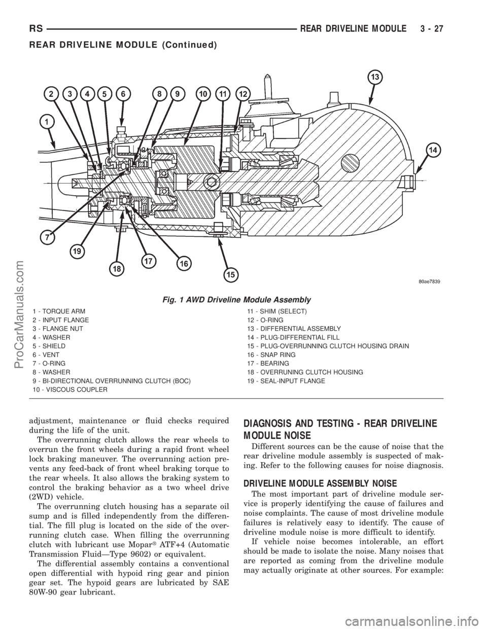
The rear driveline module assembly (Fig. 1) con-
sists of four main components:
²Bi-Directional Overrunning Clutch (BOC)
²Viscous Coupling
²Differential Assembly
²Torque Arm
The viscous coupling and bi-directional overrun-
ning clutch are contained within an overrunning
clutch housing, which fastens to the differential
assembly. The overrunning clutch housing and differ-
ential assembly have unique fluid sumps, each
requiring their own type and capacity of fluid. The
overrunning clutch housing requires MopartATF+4
(Automatic Transmission FluidÐType 9602) or equiv-
alent. The differential assembly requires
Driveline module service is limited to the following
components:
²Differential Assembly (serviced only as assem-
bly)
²Viscous Coupling
²Bi-Directional Overrunning Clutch (BOC)
²Overrunning Clutch Housing
²Seals (Input Flange, Output Flange, Overrun-
ning Clutch Housing O-rings)
²Input Flange/Shield²Torque Arm
²Vents
²FastenersOPERATION
The primary benefits of All Wheel Drive are:
²Superior straight line acceleration, and corner-
ing on all surfaces
²Better traction and handling under adverse con-
ditions, resulting in improved hill climbing ability
and safer driving.
The heart of the system is an inter-axle viscous
coupling. The vehicle retains predominantly front-
wheel drive characteristics, but the All Wheel Drive
capability takes effect when the front wheels start to
slip. Under normal level road, straight line driving,
100% of the torque is allocated to the front wheels.
The viscous coupling controls and distributes torque/
power to the rear wheels. The viscous coupling trans-
mits torque to the rear wheels in proportion of the
amount of the slippage at the front wheels. Thais
variable torque distribution is automatic with no
driver inputs required. The coupling is similar to a
multi-plate clutch. It consists of a series of closely
spaced discs, which are alternately connected to the
front and rear drive units. The unit is totally sealed
and partially filled with silicone fluid. There is no
3 - 26 REAR DRIVELINE MODULERS
ProCarManuals.com
Page 136 of 2321
adjustment, maintenance or fluid checks required
during the life of the unit.
The overrunning clutch allows the rear wheels to
overrun the front wheels during a rapid front wheel
lock braking maneuver. The overrunning action pre-
vents any feed-back of front wheel braking torque to
the rear wheels. It also allows the braking system to
control the braking behavior as a two wheel drive
(2WD) vehicle.
The overrunning clutch housing has a separate oil
sump and is filled independently from the differen-
tial. The fill plug is located on the side of the over-
running clutch case. When filling the overrunning
clutch with lubricant use MopartATF+4 (Automatic
Transmission FluidÐType 9602) or equivalent.
The differential assembly contains a conventional
open differential with hypoid ring gear and pinion
gear set. The hypoid gears are lubricated by SAE
80W-90 gear lubricant.DIAGNOSIS AND TESTING - REAR DRIVELINE
MODULE NOISE
Different sources can be the cause of noise that the
rear driveline module assembly is suspected of mak-
ing. Refer to the following causes for noise diagnosis.
DRIVELINE MODULE ASSEMBLY NOISE
The most important part of driveline module ser-
vice is properly identifying the cause of failures and
noise complaints. The cause of most driveline module
failures is relatively easy to identify. The cause of
driveline module noise is more difficult to identify.
If vehicle noise becomes intolerable, an effort
should be made to isolate the noise. Many noises that
are reported as coming from the driveline module
may actually originate at other sources. For example:
Fig. 1 AWD Driveline Module Assembly
1 - TORQUE ARM
2 - INPUT FLANGE
3 - FLANGE NUT
4 - WASHER
5 - SHIELD
6 - VENT
7 - O-RING
8 - WASHER
9 - BI-DIRECTIONAL OVERRUNNING CLUTCH (BOC)
10 - VISCOUS COUPLER11 - SHIM (SELECT)
12 - O-RING
13 - DIFFERENTIAL ASSEMBLY
14 - PLUG-DIFFERENTIAL FILL
15 - PLUG-OVERRUNNING CLUTCH HOUSING DRAIN
16 - SNAP RING
17 - BEARING
18 - OVERRUNING CLUTCH HOUSING
19 - SEAL-INPUT FLANGE
RSREAR DRIVELINE MODULE3-27
REAR DRIVELINE MODULE (Continued)
ProCarManuals.com
Page 154 of 2321

(3) Remove overrunning clutch housing drain plug
and drain fluid (Fig. 43).
(4) Install the drain plug and torque to 30 N´m (22
ft. lbs.).
(5) Re-position the drain pan under the overrun-
ning clutch housing fill plug.
(6) Remove fill plug (Fig. 44).
(7) Using a suction gun (Fig. 45), add 0.58 L (1.22
pts.) of MopartATF+4 (Automatic Transmission Flu-
idÐType 9602).
(8)
Install fill plug and torque to 30 N´m (22 ft. lbs.).
VISCOUS COUPLER
DESCRIPTION
The heart of the all-wheel drive system is the inter-
axle viscous coupling and bi-directional overrunning
clutch. Under normal driving the vehicle retains pre-
dominantly front wheel drive characteristics. The all-
wheel drive takes effect when the front wheels start to
slip. Under normal level road, straight line driving,
100% of the torque is allocated to the front wheels.
The viscous coupler allows more torque to the rear
wheels in accordance with the amount of slippage at
the front wheels. The variable torque distribution is
automatic with no driver inputs required.
OPERATION
The viscous coupler (Fig. 46) is a housing nearly
filled with a high viscosity silicone liquid and thin
metal plates alternately splined to an inner and
outer drum. The viscous coupler provides torque in
the following modes:
²Shear mode (normal operation)
²Hump mode (locked mode)
The inner plates are slotted around the radius and
the outer plates have holes in them. In the shear
mode (normal operation), the plates are evenly
spaced and the torque is created by the shearing of
the plates through the fluid and 90-100% of the
torque is applied to the rear axle. During the shear
mode, a fluid flow pattern is created from this design
(holes and slots). This fluid flow causes high pressure
on each side of each pair of plates and low pressure
between each pair of plates.
Fig. 43 Overrunning Clutch Case Drain Plug
1 - OVERRUNNING CLUTCH HOUSING DRAIN PLUG
Fig. 44 Overrunning Clutch Housing Fill Plug
1 - OVERRUNNING CLUTCH HOUSING FILL PLUG
2 - FUEL TANK
Fig. 45 Filling Overrunning Clutch Case
1 - OVERRUNNING CLUTCH HOUSING FILL HOLE
2 - SUCTION GUN
RSREAR DRIVELINE MODULE3-45
FLUID (Continued)
ProCarManuals.com
Page 268 of 2321
COOLING
TABLE OF CONTENTS
page page
COOLING
DESCRIPTION............................1
OPERATION.............................1
DIAGNOSIS AND TESTING..................3
COOLING SYSTEM LEAK TEST.............3
COOLING SYSTEM FLOW CHECK..........3
COOLING SYSTEM AERATION.............3
COOLING SYSTEM DEAERATION...........3
STANDARD PROCEDURE...................4COOLING SYSTEM - DRAINING............4
COOLING SYSTEM - REFILLING............4
COOLANT - ADDING ADDITIONAL...........4
COOLANT LEVEL CHECK - ROUTINE........5
SPECIFICATIONS.........................6
SPECIAL TOOLS..........................6
ACCESSORY DRIVE.......................7
ENGINE................................13
TRANSMISSION.........................36
COOLING
DESCRIPTION - COOLING SYSTEM
The cooling system components consist of a radia-
tor, electric fan motors, shroud, pressure cap, thermo-
stat, transmission oil cooler, water pump, hoses,
clamps, coolant, and a coolant reserve system to com-
plete the circuit.
DESCRIPTION - HOSE CLAMPS
The cooling system uses spring type hose clamps.
If a spring type clamp replacement is necessary,
replace with the original Mopartequipment spring
type clamp.
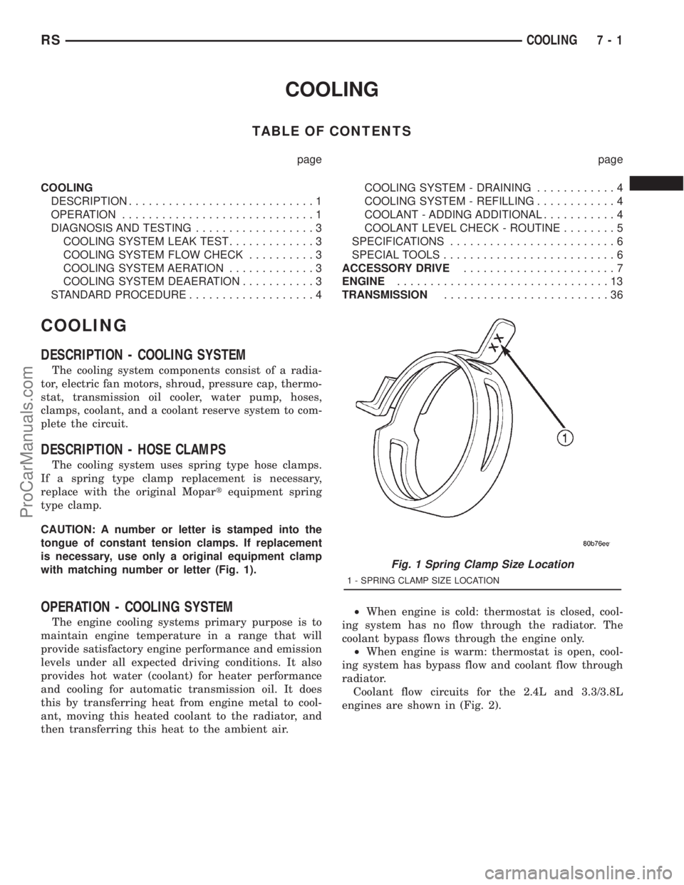
CAUTION: A number or letter is stamped into the
tongue of constant tension clamps. If replacement
is necessary, use only a original equipment clamp
with matching number or letter (Fig. 1).
OPERATION - COOLING SYSTEM
The engine cooling systems primary purpose is to
maintain engine temperature in a range that will
provide satisfactory engine performance and emission
levels under all expected driving conditions. It also
provides hot water (coolant) for heater performance
and cooling for automatic transmission oil. It does
this by transferring heat from engine metal to cool-
ant, moving this heated coolant to the radiator, and
then transferring this heat to the ambient air.²When engine is cold: thermostat is closed, cool-
ing system has no flow through the radiator. The
coolant bypass flows through the engine only.
²When engine is warm: thermostat is open, cool-
ing system has bypass flow and coolant flow through
radiator.
Coolant flow circuits for the 2.4L and 3.3/3.8L
engines are shown in (Fig. 2).
Fig. 1 Spring Clamp Size Location
1 - SPRING CLAMP SIZE LOCATION
RSCOOLING7-1
ProCarManuals.com
Page 303 of 2321
TRANSMISSION
TABLE OF CONTENTS
page page
TRANSMISSION
DIAGNOSIS AND TESTING.................36
TRANS OIL COOLER FLOW TESTING.......36
STANDARD PROCEDURE..................37
FLUSHING COOLERS AND TUBES.........37
TRANS COOLER
DESCRIPTION...........................38REMOVAL..............................38
CLEANING..............................38
INSPECTION............................38
INSTALLATION...........................38
TRANS COOLER LINES
REMOVAL..............................38
INSTALLATION...........................39
TRANSMISSION
DIAGNOSIS AND TESTING - TRANSMISSION
OIL COOLER FLOW
To determine proper transmission oil flow through
the oil cooler perform the following procedure:
(1) Disconnect the hose from the ªcooler returnº
fitting on the transmission. (Refer to 7 - COOLING/
TRANSMISSION/TRANS COOLER LINES -
REMOVAL)
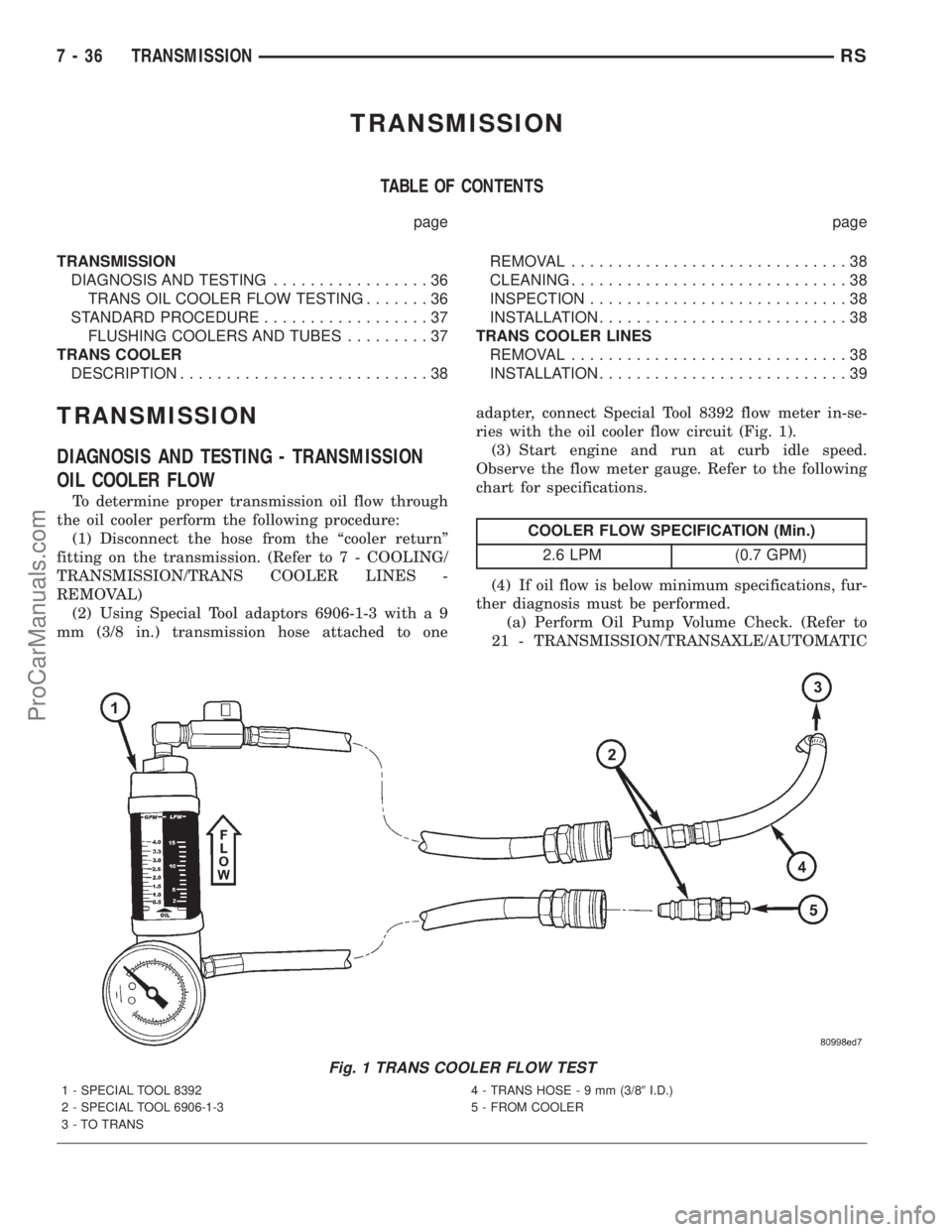
(2) Using Special Tool adaptors 6906-1-3 with a 9
mm (3/8 in.) transmission hose attached to oneadapter, connect Special Tool 8392 flow meter in-se-
ries with the oil cooler flow circuit (Fig. 1).
(3) Start engine and run at curb idle speed.
Observe the flow meter gauge. Refer to the following
chart for specifications.
COOLER FLOW SPECIFICATION (Min.)
2.6 LPM (0.7 GPM)
(4) If oil flow is below minimum specifications, fur-
ther diagnosis must be performed.
(a) Perform Oil Pump Volume Check. (Refer to
21 - TRANSMISSION/TRANSAXLE/AUTOMATIC
Fig. 1 TRANS COOLER FLOW TEST
1 - SPECIAL TOOL 8392 4 - TRANS HOSE-9mm(3/89I.D.)
2 - SPECIAL TOOL 6906-1-3 5 - FROM COOLER
3 - TO TRANS
7 - 36 TRANSMISSIONRS
ProCarManuals.com
Page 304 of 2321
- 31TH/OIL PUMP - STANDARD PROCEDURE)
(Refer to 21 - TRANSMISSION/TRANSAXLE/AU-
TOMATIC - 41TE/OIL PUMP - STANDARD PRO-
CEDURE)
(b) If oil pump volume is within specification, a
possible restriction in the cooler lines or cooler has
occurred.
(c) If oil pump volume is not within specification,
possible internal transmission restrictions, compo-
nent wear or damage has occurred. (Refer to 21 -
TRANSMISSION/TRANSAXLE/AUTOMATIC -
31TH - DIAGNOSIS AND TESTING) (Refer to 21 -
TRANSMISSION/TRANSAXLE/AUTOMATIC -
41TE - DIAGNOSIS AND TESTING)
(d) If an oil cooler restriction is suspected, per-
form further inspections and flow meter testing by
isolating components (i.e. lines, coolers).
(e) After a restriction is isolated, perform cooler
flush procedure. (Refer to 7 - COOLING/TRANS-
MISSION - STANDARD PROCEDURE)
(f) Re-test cooler flow. If cooler flow does not
exceed minimum specification, replace compo-
nent(s) as necessary.
STANDARD PROCEDURE - FLUSHING
COOLERS AND TUBES
The recommended procedure for cooler flushing is
to use Tool 6906 Cooler Flusher.
WARNING:
WEAR PROTECTIVE EYEWEAR THAT MEETS THE
REQUIREMENTS OF OSHA AND ANSI Z87.1±1968.
WEAR STANDARD INDUSTRIAL RUBBER GLOVES.
KEEP LIGHTED CIGARETTES, SPARKS, FLAMES,
AND OTHER IGNITION SOURCES AWAY FROM THE
AREA TO PREVENT THE IGNITION OF COMBUSTI-
BLE LIQUIDS AND GASES. KEEP A CLASS (B) FIRE
EXTINGUISHER IN THE AREA WHERE THE
FLUSHER WILL BE USED.
KEEP THE AREA WELL VENTILATED.
DO NOT LET FLUSHING SOLVENT COME IN CON-
TACT WITH YOUR EYES OR SKIN: IF EYE CONTAM-
INATION OCCURS, FLUSH EYES WITH WATER FOR15 TO 20 SECONDS. REMOVE CONTAMINATED
CLOTHING AND WASH AFFECTED SKIN WITH
SOAP AND WATER. SEEK MEDICAL ATTENTION.
(1) Remove cover plate filler plug on Tool 6906.
Fill reservoir 1/2 to 3/4 full of fresh flushing solution.
Use MopartTransmission Cooler Flush (MS-552) or
equivalent solution conforming to MS-552. Flushing
solvents are petroleum based solutions generally
used to clean automatic transmission components.
DO NOTuse solvents containing acids, water, gaso-
line, or any other corrosive liquids.
(2) Reinstall filler plug on Tool 6906.
(3) Verify pump power switch is turned OFF. Con-
nect red alligator clip to positive (+) battery post.
Connect black (-) alligator clip to a good ground.
NOTE: When flushing transmission cooler and
lines, ALWAYS reverse flush.
(4) Connect the BLUE pressure line to the OUT-
LET (From) cooler line.
(5) Connect the CLEAR return line to the INLET
(To) cooler line
(6) Turn pump ON for two to three minutes to
flush cooler and lines.
(7) Turn pump OFF.
(8) Disconnect CLEAR suction line from reservoir
at cover plate. Disconnect CLEAR return line at
cover plate, and place it in a drain pan.
(9) Turn pump ON for 30 seconds to purge flush-
ing solution from cooler and lines. Turn pump OFF.
(10) Place CLEAR suction line into a one quart
container of MopartATF+4 (Automatic Transmission
FluidÐType 9602).
(11) Turn pump ON until all transmission fluid is
removed from the one quart container and lines. This
purges any residual cleaning solvent from the trans-
mission cooler and lines. Turn pump OFF.
(12) Disconnect alligator clips from battery. Recon-
nect flusher lines to cover plate, and remove flushing
adapters from cooler lines.
RSTRANSMISSION7-37
TRANSMISSION (Continued)
ProCarManuals.com
Page 366 of 2321
²Throttle Position Sensor
²Torque Management Input (From TCM)
²Transaxle Control Module (TCM)
²Transaxle Gear Engagement (From TCM)
²Vehicle Speed (from transmission control mod-
ule)
NOTE: PCM Outputs:
²Air Conditioning Clutch Relay
²Automatic Shut Down (ASD) and Fuel Pump
Relays
²Data Link Connector (PCI and SCI Transmit)
²Double Start Override
²EGR Solenoid
²Fuel Injectors
²Generator Field
²High Speed Fan Relay
²Idle Air Control Motor
²Ignition Coils
²Leak Detection Pump
²Low Speed Fan Relay
²MTV Actuator
²Proportional Purge Solenoid
²SRV Valve
²Speed Control Relay
²Speed Control Vent Relay
²Speed Control Vacuum Relay
²8 Volt Output
²5 Volt Output
Based on inputs it receives, the powertrain control
module (PCM) adjusts fuel injector pulse width, idle
speed, ignition timing, and canister purge operation.
The PCM regulates the cooling fans, air conditioning
and speed control systems. The PCM changes gener-
ator charge rate by adjusting the generator field.
The PCM adjusts injector pulse width (air-fuel
ratio) based on the following inputs.
²Battery Voltage
²Intake Air Temperature Sensor
²Engine Coolant Temperature
²Engine Speed (crankshaft position sensor)
²Exhaust Gas Oxygen Content (heated oxygen
sensors)
²Manifold Absolute Pressure
²Throttle Position
The PCM adjusts engine idle speed through the
idle air control motor based on the following inputs.
²Brake Switch
²Engine Coolant Temperature
²Engine Speed (crankshaft position sensor)
²Park/Neutral (transmission gear selection)
²Transaxle Gear Engagement
²Throttle Position
²Vehicle Speed (from Transmission Control Mod-
ule)The PCM adjusts ignition timing based on the fol-
lowing inputs.
²Intake Air Temperature
²Engine Coolant Temperature
²Engine Speed (crankshaft position sensor)
²Knock Sensor
²Manifold Absolute Pressure
²Park/Neutral (transmission gear selection)
²Transaxle Gear Engagement
²Throttle Position
The automatic shut down (ASD) and fuel pump
relays are mounted externally, but turned on and off
by the powertrain control module through the same
circuit.
The camshaft and crankshaft signals are sent to
the powertrain control module. If the PCM does not
receive both signals within approximately one second
of engine cranking, it deactivates the ASD and fuel
pump relays. When these relays are deactivated,
power is shut off to the fuel injectors, ignition coils,
fuel pump and the heating element in each oxygen
sensor.
The PCM contains a voltage converter that
changes battery voltage to a regulated 8.0 volts. The
8.0 volts power the camshaft position sensor, crank-
shaft position sensor and vehicle speed sensor. The
PCM also provides a 5.0 volts supply for the engine
coolant temperature sensor, intake air temperature
sensor, manifold absolute pressure sensor and throt-
tle position sensor.
The PCM engine control strategy prevents reduced
idle speeds until after the engine operates for 320 km
(200 miles). If the PCM is replaced after 320 km (200
miles) of usage, update the mileage in new PCM. Use
the DRB scan tool to change the mileage in the PCM.
Refer to the appropriate Powertrain Diagnostic Man-
ual and the DRB scan tool.
DIAGNOSTIC TROUBLE CODE
DESCRIPTION
A Diagnostic Trouble Code (DTC) indicates the
PCM has recognized an abnormal condition in the
system.
Remember that DTC's are the results of a sys-
tem or circuit failure, but do not directly iden-
tify the failed component or components.
NOTE: For a list of DTC's, refer to the charts in this
section.
RSELECTRONIC CONTROL MODULES8E-9
POWERTRAIN CONTROL MODULE (Continued)
ProCarManuals.com
Page 385 of 2321
STANDARD PROCEDURE - TCC BREAK-IN
VIEW/RESTART PROCEDURE
The Transmission Control Module (TCM) employs
a strategy which modifies torque converter clutch
(TCC) operation. This strategy conditions the torque
converter clutch disc for optimum converter clutch
engagement and feel throughout the life of the trans-
axle. The cycle inhibits FEMCC until six hours of
PEMCC operation have taken place, or the vehicle
has been driven 6,035 km (3750 miles). The cycle
automatically terminates when either the time or
mileage has been achieved, however, the mileage
may vary slightly from vehicle to vehicle.
The TCC break-in cycle must be restarted using
the DRB Scan Tool, and upon:
²Replacement of TCM on vehicle with less than
6,035 km (3750 miles) or less than 6 hours of
PEMCC operation
²Replacement of torque converter assembly at
any vehicle mileage
NOTE: Failure to restart the TCC Break-In Cycle
upon TCM replacement in vehicles with less than
six hours of PEMCC or less than 6,035 km (3750
miles), or upon torque converter replacement at any
mileage, may result in vehicle shudder during cer-
tain operating conditions.
Procedure
The DRB Scan Tool is required to view and/or
restart the TCC Break-In cycle.
(1) Connect the DRB Scan Tool to the vehicle diag-
nostic connector.
(2) Navigate to ªTCC Break-Inº via Transmission/
Transmission Control Module/Miscellaneous.
(3) View or Start TCC Break-In as prompted by
DRB menu.
REMOVAL
NOTE: If transmission control module is being
replaced with a new or replacement unit, the Pinion
Factor and Quick Learn procedures must be per-
formed. (Refer to 8 - ELECTRICAL/ELECTRONIC
CONTROL MODULES/TRANSMISSION CONTROL
MODULE - STANDARD PROCEDURE) (Refer to 8 -
ELECTRICAL/ELECTRONIC CONTROL MODULES/
TRANSMISSION CONTROL MODULE - STANDARD
PROCEDURE) If vehicle has less than 6,035 km
(3750 miles), the Torque Converter Clutch (TCC)
Break-In Strategy reset procedure must also be per-
formed. (Refer to 8 - ELECTRICAL/ELECTRONIC
CONTROL MODULES/TRANSMISSION CONTROL
MODULE - STANDARD PROCEDURE)(1) Disconnect battery negative cable.
(2) Raise vehicle on hoist.
(3) Remove left front tire/wheel assembly.
(4) Pull back splash shield to gain access to TCM
location.
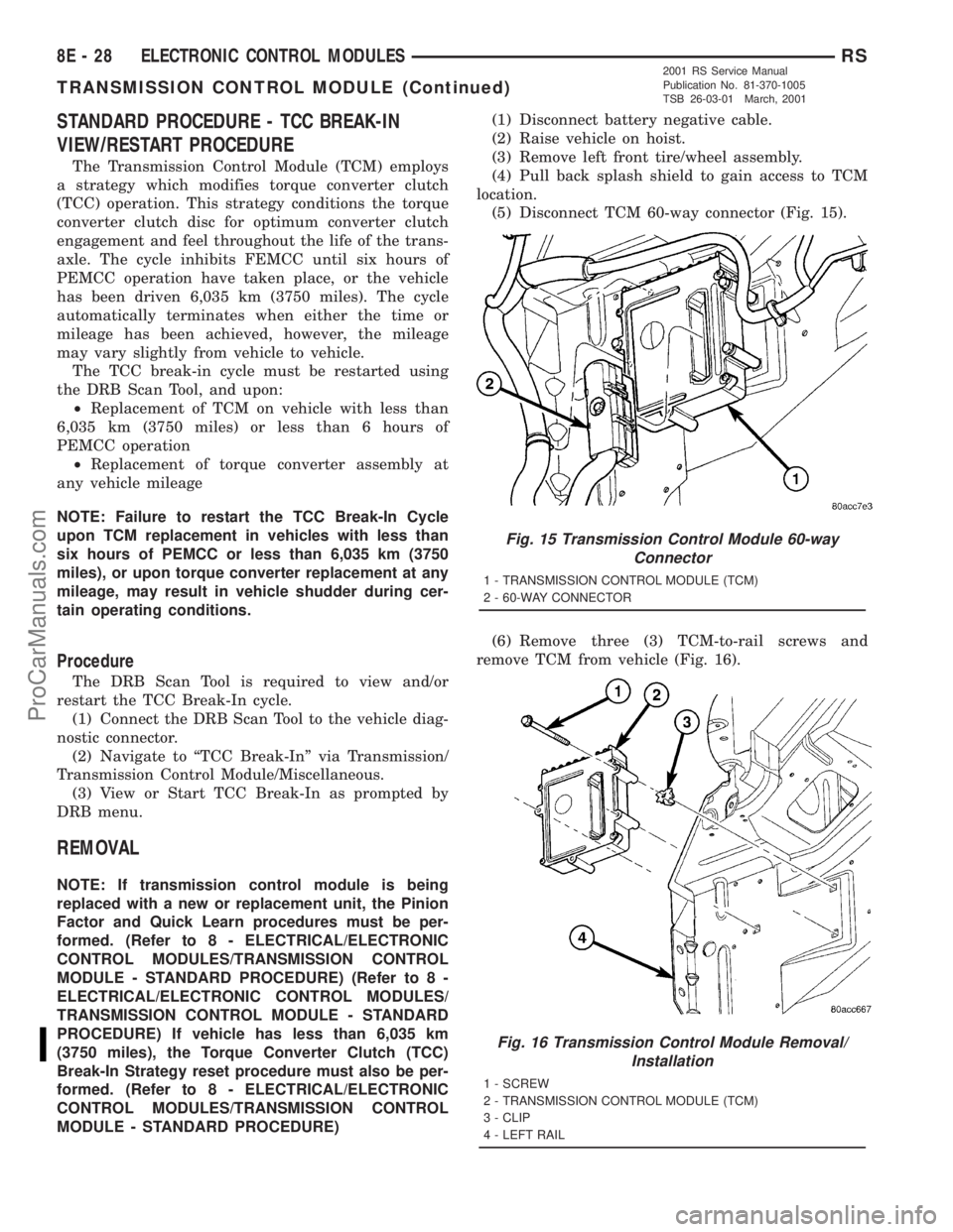
(5) Disconnect TCM 60-way connector (Fig. 15).
(6) Remove three (3) TCM-to-rail screws and
remove TCM from vehicle (Fig. 16).
Fig. 15 Transmission Control Module 60-way
Connector
1 - TRANSMISSION CONTROL MODULE (TCM)
2 - 60-WAY CONNECTOR
Fig. 16 Transmission Control Module Removal/
Installation
1 - SCREW
2 - TRANSMISSION CONTROL MODULE (TCM)
3 - CLIP
4 - LEFT RAIL
8E - 28 ELECTRONIC CONTROL MODULESRS
TRANSMISSION CONTROL MODULE (Continued)
2001 RS Service Manual
Publication No. 81-370-1005
TSB 26-03-01 March, 2001
ProCarManuals.com
Page 405 of 2321

²If the vehicle is equipped with an automatic
transmission, place the gearshift selector lever in the
Park position. If the vehicle is equipped with a man-
ual transmission, place the gearshift selector lever in
the Neutral position and block the clutch pedal in the
fully depressed position.
²Verify that all lamps and accessories are turned
off.
²To prevent the engine from starting, remove the
Automatic Shut Down (ASD) relay. The ASD relay is
located in the Intelligent Power Module (IPM), in the
engine compartment. See the fuse and relay layout
label affixed to the underside of the IPM cover for
ASD relay identification and location.
(1) Connect the positive lead of the voltmeter to
the battery negative terminal post. Connect the neg-
ative lead of the voltmeter to the battery negative
cable terminal clamp (Fig. 16). Rotate and hold the
ignition switch in the Start position. Observe the
voltmeter. If voltage is detected, correct the poor con-
nection between the battery negative cable terminal
clamp and the battery negative terminal post.
(2) Connect the positive lead of the voltmeter to
the battery positive terminal post. Connect the nega-
tive lead of the voltmeter to the battery positive cable
terminal clamp (Fig. 17). Rotate and hold the ignition
switch in the Start position. Observe the voltmeter. If
voltage is detected, correct the poor connection
between the battery positive cable terminal clamp
and the battery positive terminal post.(3) Connect the voltmeter to measure between the
battery positive cable terminal clamp and the starter
solenoid B(+) terminal stud (Fig. 18). Rotate and hold
the ignition switch in the Start position. Observe the
voltmeter. If the reading is above 0.2 volt, clean and
tighten the battery positive cable eyelet terminal con-
nection at the starter solenoid B(+) terminal stud.
Repeat the test. If the reading is still above 0.2 volt,
replace the faulty battery positive cable.
Fig. 16 Test Battery Negative Connection
Resistance - Typical
1 - VOLTMETER
2 - BATTERY
Fig. 17 Test Battery Positive Connection Resistance
- Typical
1 - VOLTMETER
2 - BATTERY
Fig. 18 Test Battery Positive Cable Resistance -
Typical
1 - BATTERY
2 - VOLTMETER
3 - STARTER MOTOR
8F - 18 BATTERY SYSTEMRS
BATTERY CABLES (Continued)
ProCarManuals.com
Page 416 of 2321
CONDITION POSSIBLE CAUSE CORRECTION
3. STARTER ASSEMBLY
FAULTY.3. IF ALL OTHER STARTING SYSTEM COMPONENTS AND
CIRCUITS CHECK OK, REPLACE STARTER ASSEMBLY.
4. ENGINE SEIZED. 4. REFER TO THE ENGINE SECTION, FOR DIAGNOSTIC AND
SERVICE PROCEDURES.
5. LOOSE
CONNECTION AT
BATTERY, PDC,
STARTER, OR ENGINE
GROUND.5. INSPECT FOR LOOSE CONNECTIONS.
6. FAULTY TEETH ON
RING GEAR.6. ROTATE FLYWHEEL 360É, AND INSPECT TEETHAND RING
GEAR REPLACED IF DAMAGED.
STARTER
ENGAGES,
SPINS OUT
BEFORE
ENGINE
STARTS.1. BROKEN TEETH ON
STARTER RING GEAR.1. REMOVE STARTER. INSPECT RING GEAR AND REPLACE
IF NECESSARY.
2. STARTER ASSEMBLY
FAULTY.2. IF ALL OTHER STARTING SYSTEM COMPONENTS AND
CIRCUITS CHECK OK, REPLACE STARTER ASSEMBLY.
STARTER DOES
NOT
DISENGAGE.1. STARTER
IMPROPERLY
INSTALLED.1. INSTALL STARTER. TIGHTEN STARTER MOUNTING
HARDWARE TO CORRECT TORQUE SPECIFICATIONS.
2. STARTER RELAY
FAULTY.2. REFER TO RELAY TEST, IN THIS SECTION. REPLACE
RELAY, IF NECESSARY.
3. IGNITION SWITCH
FAULTY.3. REFER TO IGNITION SWITCH TEST, IN THE STEERING
SECTION.. REPLACE SWITCH, IF NECESSARY.
4. STARTER ASSEMBLY
FAULTY.4. IF ALL OTHER STARTING SYSTEM COMPONENTS AND
CIRCUITS CHECK OK, REPLACE STARTER ASSEMBLY.
5. FAULTY TEETH ON
RING GEAR.5. ROTATE FLYWHEEL 360É, AND INSPECT TEETH AND RING
GEAR REPLACED IF DAMAGED.
CONTROL CIRCUIT TEST
The starter control circuit has:
²Starter motor with integral solenoid
²Starter relay
²Transmission range sensor, or Park/Neutral
Position switch with automatic transmissions
²Ignition switch
²Battery
²All related wiring and connections
²Powertrain Control Module (PCM)
CAUTION: Before performing any starter tests, the
ignition and fuel systems must be disabled.
²To disable ignition and fuel systems, disconnect
the Automatic Shutdown Relay (ASD). The ASD relay
is located in the Power Distribution Center (PDC).
Refer to the PDC cover for the proper relay location.
STARTER SOLENOID
WARNING: CHECK TO ENSURE THAT THE TRANS-
MISSION IS IN THE PARK POSITION WITH THE
PARKING BRAKE APPLIED.
(1) Verify battery condition. Battery must be in
good condition with a full charge before performing
any starter tests. Refer to Battery Tests.
(2) Perform Starter Solenoid test BEFORE per-
forming the starter relay test.
(3) Perform a visual inspection of the starter/
starter solenoid for corrosion, loose connections or
faulty wiring.
(4) Locate and remove the starter relay from the
Power Distribution Center (PDC). Refer to the PDC
label for relay identification and location.
RSSTARTING8F-29
STARTING (Continued)
ProCarManuals.com