transmission oil DODGE TOWN AND COUNTRY 2001 User Guide
[x] Cancel search | Manufacturer: DODGE, Model Year: 2001, Model line: TOWN AND COUNTRY, Model: DODGE TOWN AND COUNTRY 2001Pages: 2321, PDF Size: 68.09 MB
Page 136 of 2321
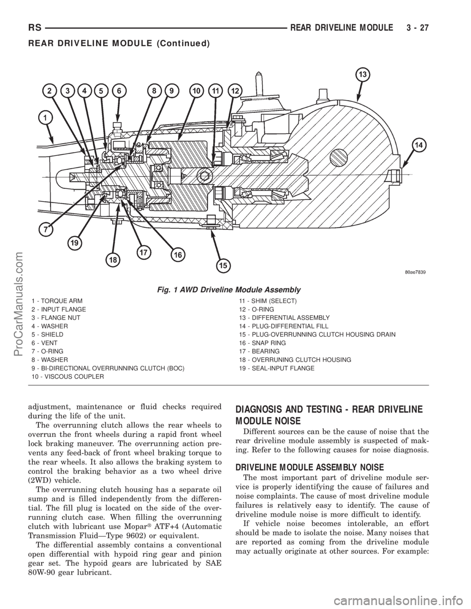
adjustment, maintenance or fluid checks required
during the life of the unit.
The overrunning clutch allows the rear wheels to
overrun the front wheels during a rapid front wheel
lock braking maneuver. The overrunning action pre-
vents any feed-back of front wheel braking torque to
the rear wheels. It also allows the braking system to
control the braking behavior as a two wheel drive
(2WD) vehicle.
The overrunning clutch housing has a separate oil
sump and is filled independently from the differen-
tial. The fill plug is located on the side of the over-
running clutch case. When filling the overrunning
clutch with lubricant use MopartATF+4 (Automatic
Transmission FluidÐType 9602) or equivalent.
The differential assembly contains a conventional
open differential with hypoid ring gear and pinion
gear set. The hypoid gears are lubricated by SAE
80W-90 gear lubricant.DIAGNOSIS AND TESTING - REAR DRIVELINE
MODULE NOISE
Different sources can be the cause of noise that the
rear driveline module assembly is suspected of mak-
ing. Refer to the following causes for noise diagnosis.
DRIVELINE MODULE ASSEMBLY NOISE
The most important part of driveline module ser-
vice is properly identifying the cause of failures and
noise complaints. The cause of most driveline module
failures is relatively easy to identify. The cause of
driveline module noise is more difficult to identify.
If vehicle noise becomes intolerable, an effort
should be made to isolate the noise. Many noises that
are reported as coming from the driveline module
may actually originate at other sources. For example:
Fig. 1 AWD Driveline Module Assembly
1 - TORQUE ARM
2 - INPUT FLANGE
3 - FLANGE NUT
4 - WASHER
5 - SHIELD
6 - VENT
7 - O-RING
8 - WASHER
9 - BI-DIRECTIONAL OVERRUNNING CLUTCH (BOC)
10 - VISCOUS COUPLER11 - SHIM (SELECT)
12 - O-RING
13 - DIFFERENTIAL ASSEMBLY
14 - PLUG-DIFFERENTIAL FILL
15 - PLUG-OVERRUNNING CLUTCH HOUSING DRAIN
16 - SNAP RING
17 - BEARING
18 - OVERRUNING CLUTCH HOUSING
19 - SEAL-INPUT FLANGE
RSREAR DRIVELINE MODULE3-27
REAR DRIVELINE MODULE (Continued)
ProCarManuals.com
Page 183 of 2321
CLEANING - CALIPER
WARNING: DUST AND DIRT ACCUMULATING ON
BRAKE PARTS DURING NORMAL USE MAY CON-
TAIN ASBESTOS FIBERS FROM PRODUCTION OR
AFTERMARKET BRAKE LININGS. BREATHING
EXCESSIVE CONCENTRATIONS OF ASBESTOS
FIBERS CAN CAUSE SERIOUS BODILY HARM.
EXERCISE CARE WHEN SERVICING BRAKE
PARTS. DO NOT SAND OR GRIND BRAKE LINING
UNLESS EQUIPMENT USED IS DESIGNED TO CON-
TAIN THE DUST RESIDUE. DO NOT CLEAN BRAKE
PARTS WITH COMPRESSED AIR OR BY DRY
BRUSHING. CLEANING SHOULD BE DONE BY
DAMPENING THE BRAKE COMPONENTS WITH A
FINE MIST OF WATER, THEN WIPING THE BRAKE
COMPONENTS CLEAN WITH A DAMPENED CLOTH.
DISPOSE OF CLOTH AND ALL RESIDUE CONTAIN-
ING ASBESTOS FIBERS IN AN IMPERMEABLE
CONTAINER WITH THE APPROPRIATE LABEL. FOL-
LOW PRACTICES PRESCRIBED BY THE OCCUPA-
TIONAL SAFETY AND HEALTH ADMINISTRATION
(OSHA) AND THE ENVIRONMENTAL PROTECTION
AGENCY (EPA) FOR THE HANDLING, PROCESSING,
AND DISPOSING OF DUST OR DEBRIS THAT MAY
CONTAIN ASBESTOS FIBERS.
To clean or flush the internal passages of the brake
caliper, use fresh brake fluid or MopartNon-Chlori-
nated Brake Parts Cleaner. Never use gasoline, ker-
osene, alcohol, oil, transmission fluid or any fluid
containing mineral oil to clean the caliper. These flu-
ids will damage rubber cups and seals.
INSPECTION - CALIPER
Inspect the disc brake caliper for the following:
²Brake fluid leaks in and around boot area and
inboard lining
²Ruptures, brittleness or damage to the piston
dust boot
²Damaged, dry or brittle guide pin dust boots
If caliper fails inspection, disassemble and recondi-
tion caliper, replacing the seals and dust boots.
ASSEMBLY - CALIPER GUIDE PIN BUSHINGS
(DISC/DISC BRAKES)
(1) Fold the guide pin bushing in half lengthwise.
NOTE: To avoid damage to the bushing, do not use
a sharp object to install the guide pin bushing.
(2) Insert the folded bushing into the caliper
mounting boss using your fingers from the rear of
the caliper.
(3) Unfold the bushing using your fingers or a
wooden dowel until the bushing is fully seated intothe caliper housing. The bushing flanges should be
seated evenly on both sides of the bushing hole.
(4) Lubricate inside surfaces of bushing using
MopartDielectric Grease or equivalent.
(5) Repeat the procedure for remaining bushing.
ASSEMBLY - CALIPER PISTON AND SEAL
NOTE: Never use an old piston seal.
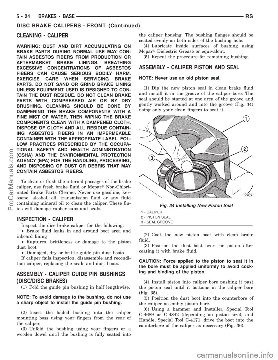
(1) Dip the new piston seal in clean brake fluid
and install it in the groove of the caliper bore. The
seal should be started at one area of the groove and
gently worked around and into the groove (Fig. 34)
using only your clean fingers to seat it.
(2) Coat the new piston boot with clean brake
fluid.
(3) Position the dust boot over the piston after
coating it with brake fluid.
CAUTION: Force applied to the piston to seat it in
the bore must be applied uniformly to avoid cock-
ing and binding of the piston.
(4) Install piston into caliper bore pushing it past
the piston seal until it bottoms in the caliper bore
(Fig. 35).
(5) Position the dust boot into the counterbore of
the caliper assembly piston bore.
(6) Using a hammer and Installer, Special Tool
C-4689 or C-4842 (depending on piston size), and
Handle, Special Tool C-4171, drive the boot into the
counterbore of the caliper as necessary (Fig. 36).
Fig. 34 Installing New Piston Seal
1 - CALIPER
2 - PISTON SEAL
3 - SEAL GROOVE
5 - 24 BRAKES - BASERS
DISC BRAKE CALIPERS - FRONT (Continued)
ProCarManuals.com
Page 187 of 2321
CLEANING - CALIPER
WARNING: DUST AND DIRT ACCUMULATING ON
BRAKE PARTS DURING NORMAL USE MAY CON-
TAIN ASBESTOS FIBERS FROM PRODUCTION OR
AFTERMARKET BRAKE LININGS. BREATHING
EXCESSIVE CONCENTRATIONS OF ASBESTOS
FIBERS CAN CAUSE SERIOUS BODILY HARM.
EXERCISE CARE WHEN SERVICING BRAKE
PARTS. DO NOT SAND OR GRIND BRAKE LINING
UNLESS EQUIPMENT USED IS DESIGNED TO CON-
TAIN THE DUST RESIDUE. DO NOT CLEAN BRAKE
PARTS WITH COMPRESSED AIR OR BY DRY
BRUSHING. CLEANING SHOULD BE DONE BY
DAMPENING THE BRAKE COMPONENTS WITH A
FINE MIST OF WATER, THEN WIPING THE BRAKE
COMPONENTS CLEAN WITH A DAMPENED CLOTH.
DISPOSE OF CLOTH AND ALL RESIDUE CONTAIN-
ING ASBESTOS FIBERS IN AN IMPERMEABLE
CONTAINER WITH THE APPROPRIATE LABEL. FOL-
LOW PRACTICES PRESCRIBED BY THE OCCUPA-
TIONAL SAFETY AND HEALTH ADMINISTRATION
(OSHA) AND THE ENVIRONMENTAL PROTECTION
AGENCY (EPA) FOR THE HANDLING, PROCESSING,
AND DISPOSING OF DUST OR DEBRIS THAT MAY
CONTAIN ASBESTOS FIBERS.
To clean or flush the internal passages of the brake
caliper, use fresh brake fluid or MopartNon-Chlori-
nated Brake Parts Cleaner. Never use gasoline, ker-
osene, alcohol, oil, transmission fluid or any fluid
containing mineral oil to clean the caliper. These flu-
ids will damage rubber cups and seals.
INSPECTION - CALIPER
Inspect the disc brake caliper for the following:
²Brake fluid leaks in and around boot area and
inboard lining
²Ruptures, brittleness or damage to the piston
dust boot
²Damaged, dry or brittle guide pin dust boots
If caliper fails inspection, disassemble and recondi-
tion caliper, replacing the seals and dust boots.
ASSEMBLY - CALIPER PISTON AND SEAL
NOTE: Never use an old piston seal.
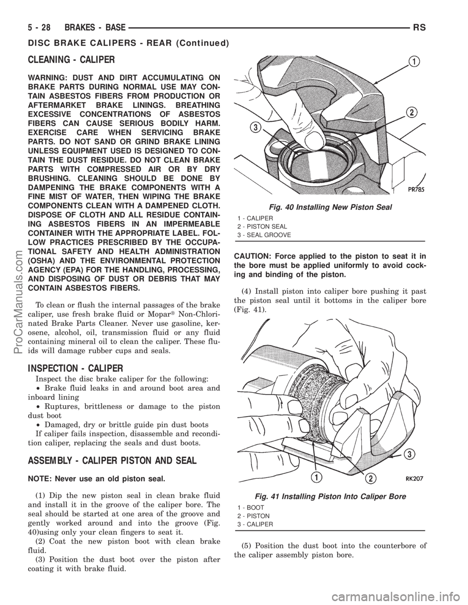
(1) Dip the new piston seal in clean brake fluid
and install it in the groove of the caliper bore. The
seal should be started at one area of the groove and
gently worked around and into the groove (Fig.
40)using only your clean fingers to seat it.
(2) Coat the new piston boot with clean brake
fluid.
(3) Position the dust boot over the piston after
coating it with brake fluid.CAUTION: Force applied to the piston to seat it in
the bore must be applied uniformly to avoid cock-
ing and binding of the piston.
(4) Install piston into caliper bore pushing it past
the piston seal until it bottoms in the caliper bore
(Fig. 41).
(5) Position the dust boot into the counterbore of
the caliper assembly piston bore.
Fig. 40 Installing New Piston Seal
1 - CALIPER
2 - PISTON SEAL
3 - SEAL GROOVE
Fig. 41 Installing Piston Into Caliper Bore
1 - BOOT
2 - PISTON
3 - CALIPER
5 - 28 BRAKES - BASERS
DISC BRAKE CALIPERS - REAR (Continued)
ProCarManuals.com
Page 191 of 2321
STANDARD PROCEDURE - BRAKE FLUID
LEVEL CHECKING
Check master cylinder reservoir fluid level a mini-
mum of twice annually.
Fluid reservoirs are marked with the words FULL
and ADD to indicate proper brake fluid fill level of
the master cylinder.
If necessary, add brake fluid to bring the level to
the bottom of the FULL mark on the side of the mas-
ter cylinder fluid reservoir.
Use only Mopartbrake fluid or equivalent from a
sealed container. Brake fluid must conform to DOT 3
specifications (DOT 4 or DOT 4+ are acceptable).
DO NOTuse brake fluid with a lower boiling
point, as brake failure could result during prolonged
hard braking.
Use only brake fluid that was stored in a tightly-
sealed container.
DO NOTuse petroleum-based fluid because seal
damage will result. Petroleum based fluids would be
items such as engine oil, transmission fluid, power
steering fluid etc.
SPECIFICATIONS
BRAKE FLUID
The brake fluid used in this vehicle must conform
to DOT 3 specifications (DOT 4 and DOT 4+ are
acceptable) and SAE J1703 standards. No other type
of brake fluid is recommended or approved for usage
in the vehicle brake system. Use only MopartBrake
Fluid or equivalent from a tightly sealed container.
CAUTION: Never use reclaimed brake fluid or fluid
from an container which has been left open. An
open container of brake fluid will absorb moisture
from the air and contaminate the fluid.
CAUTION: Never use any type of a petroleum-based
fluid in the brake hydraulic system. Use of such
type fluids will result in seal damage of the vehicle
brake hydraulic system causing a failure of the
vehicle brake system. Petroleum based fluids would
be items such as engine oil, transmission fluid,
power steering fluid, etc.
JUNCTION BLOCK
DESCRIPTION - NON-ABS JUNCTION BLOCK
A junction block is used on vehicles that are not
equipped with antilock brakes (ABS). The junction
block mounts in the same location as the integrated
control unit (ICU) does on vehicles equipped withABS. This allows for use of the same brake tube con-
figuration on all vehicles. The junction block is
located on the driver's side of the front suspension
cradle/crossmember below the master cylinder (Fig.
46).
It has six threaded ports to which the brake tubes
connect. Two are for the primary and secondary
brake tubes coming from the master cylinder. The
remaining four are for the chassis brake tubes going
to each brake assembly.
OPERATION - NON-ABS JUNCTION BLOCK
The junction block distributes the brake fluid com-
ing from the master cylinder primary and secondary
ports to the four chassis brake tubes leading to the
brakes at each wheel. Since the junction block
mounts in the same location as the ABS integrated
control unit (ICU), it allows for the common use of
brake tubes going to the brakes whether the vehicle
is equipped with or without ABS.
NOTE: Although the brake tubes coming from the
master cylinder to the junction block or ABS ICU
may appear to be the same, they are not. They are
unique to each brake system application.
REMOVAL - NON-ABS JUNCTION BLOCK
(1) Using a brake pedal depressor, move and lock
the brake pedal to a position past its first 1 inch of
travel. This will prevent brake fluid from draining
out of the master cylinder when the brake tubes are
removed from the junction block.
(2) Disconnect the battery negative cable.
(3) If the vehicle is equipped with speed control,
perform the following:
(a) Disconnect the battery positive cable.
(b) Remove the battery (Refer to 8 - ELECTRI-
CAL/BATTERY SYSTEM/BATTERY - REMOVAL).
(c) Disconnect the vacuum hose connector at the
tank built into the battery tray.
(d) Remove the screw securing the coolant filler
neck to the battery tray.
(e) Remove the battery tray (Refer to 8 - ELEC-
TRICAL/BATTERY SYSTEM/TRAY - REMOVAL).
(f) Remove the fasteners and move the speed
control servo off to the side, out of the way.
CAUTION: Before removing the brake tubes from
the junction block, the junction block and the brake
tubes must be thoroughly cleaned. This is required
to prevent contamination from entering the brake
hydraulic system.
5 - 32 BRAKES - BASERS
FLUID (Continued)
ProCarManuals.com
Page 239 of 2321
Use only brake fluid that was stored in a tightly-
sealed container.
DO NOTuse petroleum-based fluid because seal
damage will result. Petroleum based fluids would be
items such as engine oil, transmission fluid, power
steering fluid etc.
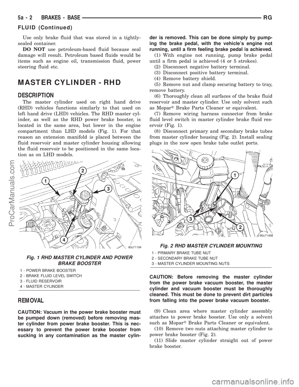
MASTER CYLINDER - RHD
DESCRIPTION
The master cylinder used on right hand drive
(RHD) vehicles functions similarly to that used on
left hand drive (LHD) vehicles. The RHD master cyl-
inder, as well as the RHD power brake booster, is
located in the same area, but lower in the engine
compartment than LHD models (Fig. 1). For that
reason an extension manifold is placed between the
fluid reservoir and master cylinder housing allowing
the fluid reservoir to be positioned in the same loca-
tion as on LHD models.
REMOVAL
CAUTION: Vacuum in the power brake booster must
be pumped down (removed) before removing mas-
ter cylinder from power brake booster. This is nec-
essary to prevent the power brake booster from
sucking in any contamination as the master cylin-der is removed. This can be done simply by pump-
ing the brake pedal, with the vehicle's engine not
running, until a firm feeling brake pedal is achieved.
(1) With engine not running, pump brake pedal
until a firm pedal is achieved (4 or 5 strokes).
(2) Disconnect negative battery terminal.
(3) Disconnect positive battery terminal.
(4) Remove battery shield.
(5) Remove nut and clamp securing battery to tray,
remove battery.
(6) Thoroughly clean all surfaces of the brake fluid
reservoir and master cylinder. Use only solvent such
as MopartBrake Parts Cleaner or equivalent.
(7) Remove wiring harness connector from brake
fluid level switch in master cylinder brake fluid res-
ervoir (Fig. 1).
(8) Disconnect primary and secondary brake tubes
from master cylinder housing (Fig. 2). Install sealing
plugs in the now open brake tube outlet ports.
CAUTION: Before removing the master cylinder
from the power brake vacuum booster, the master
cylinder and vacuum booster must be thoroughly
cleaned. This must be done to prevent dirt particles
from falling into the power brake vacuum booster.
(9) Clean area where master cylinder assembly
attaches to power brake booster. Use only a solvent
such as MopartBrake Parts Cleaner or equivalent.
(10) Remove two nuts attaching master cylinder to
power brake booster (Fig. 2).
(11) Slide master cylinder straight out of power
brake booster.
Fig. 1 RHD MASTER CYLINDER AND POWER
BRAKE BOOSTER
1 - POWER BRAKE BOOSTER
2 - BRAKE FLUID LEVEL SWITCH
3 - FLUID RESERVOIR
4 - MASTER CYLINDER
Fig. 2 RHD MASTER CYLINDER MOUNTING
1 - PRIMARY BRAKE TUBE NUT
2 - SECONDARY BRAKE TUBE NUT
3 - MASTER CYLINDER MOUNTING NUTS
5a - 2 BRAKES - BASERG
FLUID (Continued)
ProCarManuals.com
Page 255 of 2321
DIAGNOSIS AND TESTING - CLUTCH SYSTEM
Clutch problem diagnosis will generally require a
road test to determine the type of fault. Component
inspection will then determine the problem after road
testing.
Drive the vehicle at normal speeds during road
test. Shift the transaxle through all gear ranges and
observe clutch action. If chatter, grab, slip, or
improper release is experienced, remove and inspect
the clutch components. If the problem is noise or
hard shifting, further diagnosis may be needed. The
transaxle or other driveline components may actually
be at fault.
SERVICE DIAGNOSIS - CLUTCH GRAB/CHATTER
CONDITION POSSIBLE CAUSES CORRECTION
CLUTCH DISC FACING
COVERED WITH OIL OR
GREASEOil leak at engine rear main or
transaxle input shaft seal.Correct leak and replace modular clutch
assembly (2.4L Gas) or clutch cover and
disc (2.5L TD).
Too much grease applied to splines
of disc and input shaft.Apply lighter coating of grease to splines.
NO FAULT FOUND WITH
CLUTCH
COMPONENTSProblem actually related to
suspension or driveline component.Further diagnosis required. Check
engine/transmission mounts, suspension
attaching parts and other driveline
components as needed.
Engine related problems. Check EFI and ignition systems.
PARTIAL ENGAGEMENT
OF CLUTCH DISCClutch cover, spring, or release
fingers bent, distorted (rough
handling, improper assembly).Replace modular clutch assembly (2.4L
Gas) or clutch cover and disc (2.5L TD).
Clutch disc damaged or distorted. Replace modular clutch assembly (2.4L
Gas) or clutch cover and disc (2.5L TD).
Clutch misalignment. Verify modular clutch pilot plate alignment
to crankshaft. Replace the modular clutch
assembly (2.4L Gas) or clutch cover and
disc (2.5L TD) if the pilot plate is loose or
bent.
Improper transaxle-to-engine
installation.Verify transaxle is properly installed to
engine.
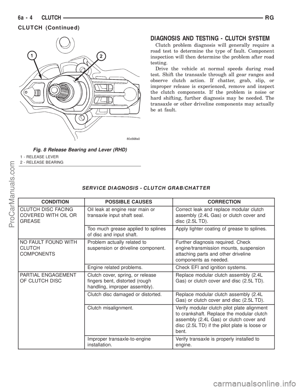
Fig. 8 Release Bearing and Lever (RHD)
1 - RELEASE LEVER
2 - RELEASE BEARING
6a - 4 CLUTCHRG
CLUTCH (Continued)
ProCarManuals.com
Page 256 of 2321
SERVICE DIAGNOSIS - CLUTCH SLIPS
CONDITION POSSIBLE CAUSES CORRECTION
DISC FACING WORN OUT Normal wear. Replace modular clutch assembly (2.4L
Gas) or clutch cover and disc (2.5L TD).
Driver frequently rides (slips) clutch,
results in rapid wear, overheating.Replace modular clutch assembly (2.4L
Gas) or clutch cover and disc (2.5L TD).
Insufficient clutch cover diaphragm
spring tensionReplace modular clutch assembly (2.4L
Gas) or clutch cover and disc (2.5L TD).
CLUTCH DISC FACING
CONTAMINATED WITH
OIL OR GREASELeak at rear main oil seal or
transaxle input shaft sealReplace leaking seals. Replace modular
clutch assembly (2.4L Gas) or clutch cover
and disc (2.5L TD).
Excessive amount of grease applied
to input shaft splinesApply less grease to input shaft. Replace
modular clutch assembly (2.4L Gas) or
clutch cover and disc (2.5L TD).
Road splash, water entering housing Seal housing. Inspect clutch assembly.
CLUTCH IS RUNNING
PARTIALLY DISENGAGEDRelease bearing sticking or binding,
does not return to normal running
position.Verify that bearing is actually binding. Then,
replace bearing and transmission front
bearing retainer if sleeve surface is
damaged.
Clutch pedal not returning to static
position.Inspect pedal assembly for damage and/or
obstructions. Replace componnents as
necessary.
Cable self-adjuster mechanism (LHD
Models) sticking or binding causing
high preload.Verify that self-adjuster is free to move.
Replace clutch release cable if necessary.
Clutch master cylinder (RHD Models)
or pushrod damaged causing high
preload.Replace clutch master cylinder assembly.
Slave cylinder binding or stuck (RHD
Models).Replace slave cylinder.
CLUTCH DISC FACINGS
HAVE FRACTURED INTO
SMALL PIECESLeak at rear main or transaxle input
shaft sealReplace seal. Replace modular clutch
assembly (2.4L Gas) or clutch cover and
disc (2.5L TD)..
Excessive heat from slippage Replace modular clutch assembly (2.4L
Gas) or clutch cover and disc (2.5L TD).
RGCLUTCH6a-5
CLUTCH (Continued)
ProCarManuals.com
Page 258 of 2321
DIAGNOSIS AND TESTING - DRIVE PLATE
MISALIGNMENT
Common causes of misalignment are:
²Heat warping
²Mounting drive plate on a dirty crankshaft
flange
²Incorrect bolt tightening
²Improper seating on the crankshaft shoulder
²Loose crankshaft bolts
Clean the crankshaft flange before mounting the
drive plate. Dirt and grease on the flange surface
may misalign the flywheel, causing excessive runout.
Use new bolts when mounting drive plate to crank-
shaft. Tighten drive plate bolts to specified torque
only. Over-tightening can distort the drive plate hub
causing excessive runout.
DIAGNOSIS AND TESTING - CLUTCH COVER
AND DISC RUNOUT
Check condition of the clutch cover before installa-
tion. A warped cover or diaphragm spring will cause
grab and/or incomplete release or engagement. Use
care when handling the clutch assembly. Impact can
distort the cover, diaphragm spring, and release fin-
gers.
DIAGNOSIS AND TESTING - CLUTCH CHATTER
COMPLAINTS
For all clutch chatter complaints, perform the fol-
lowing:
(1) Check for loose, misaligned, or broken engine
and transmission mounts. If present, they should be
corrected at this time. Test vehicle for chatter. If
chatter is gone, there is no need to go any further.
(2) If chatter persists, check hydraulic clutch
release system is functioning properly.
(3) Check for loose connections in drivetrain. Cor-
rect any problems and determine if clutch chatter
complaints have been satisfied. If not:
(a) Remove transaxle.
(b) Check to see if the release bearing is sticky
or binding. Replace bearing, if needed.
(c) Check linkage for excessive wear on the pivot
stud and fork fingers. Replace all worn parts.
(d) Check clutch assembly for contamination
(dirt, oil). Replace clutch assembly, if required.
(e) Check to see if the clutch disc hub splines
are damaged. Replace with new clutch assembly, if
necessary.
(f) Check input shaft splines for damage.
Replace, if necessary.
(g) Check for uneven wear on clutch fingers.
(h) Check for broken clutch cover diaphragm
spring fingers. Replace with new clutch assembly,
if necessary.
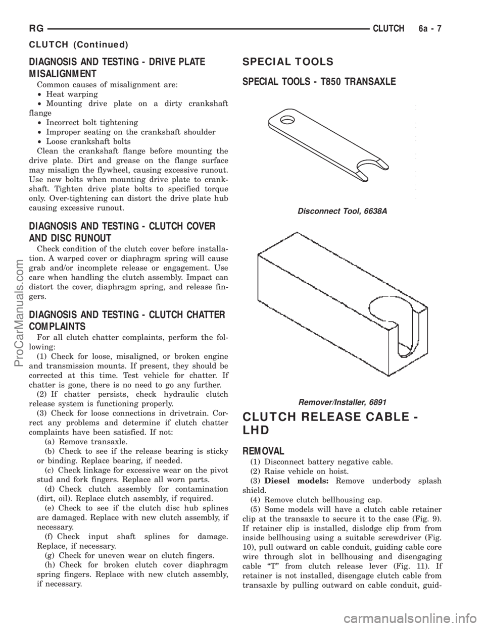
SPECIAL TOOLS
SPECIAL TOOLS - T850 TRANSAXLE
CLUTCH RELEASE CABLE -
LHD
REMOVAL
(1) Disconnect battery negative cable.
(2) Raise vehicle on hoist.
(3)Diesel models:Remove underbody splash
shield.
(4) Remove clutch bellhousing cap.
(5) Some models will have a clutch cable retainer
clip at the transaxle to secure it to the case (Fig. 9).
If retainer clip is installed, dislodge clip from from
inside bellhousing using a suitable screwdriver (Fig.
10), pull outward on cable conduit, guiding cable core
wire through slot in bellhousing and disengaging
cable ªTº from clutch release lever (Fig. 11). If
retainer is not installed, disengage clutch cable from
transaxle by pulling outward on cable conduit, guid-
Disconnect Tool, 6638A
Remover/Installer, 6891
RGCLUTCH6a-7
CLUTCH (Continued)
ProCarManuals.com
Page 268 of 2321
COOLING
TABLE OF CONTENTS
page page
COOLING
DESCRIPTION............................1
OPERATION.............................1
DIAGNOSIS AND TESTING..................3
COOLING SYSTEM LEAK TEST.............3
COOLING SYSTEM FLOW CHECK..........3
COOLING SYSTEM AERATION.............3
COOLING SYSTEM DEAERATION...........3
STANDARD PROCEDURE...................4COOLING SYSTEM - DRAINING............4
COOLING SYSTEM - REFILLING............4
COOLANT - ADDING ADDITIONAL...........4
COOLANT LEVEL CHECK - ROUTINE........5
SPECIFICATIONS.........................6
SPECIAL TOOLS..........................6
ACCESSORY DRIVE.......................7
ENGINE................................13
TRANSMISSION.........................36
COOLING
DESCRIPTION - COOLING SYSTEM
The cooling system components consist of a radia-
tor, electric fan motors, shroud, pressure cap, thermo-
stat, transmission oil cooler, water pump, hoses,
clamps, coolant, and a coolant reserve system to com-
plete the circuit.
DESCRIPTION - HOSE CLAMPS
The cooling system uses spring type hose clamps.
If a spring type clamp replacement is necessary,
replace with the original Mopartequipment spring
type clamp.
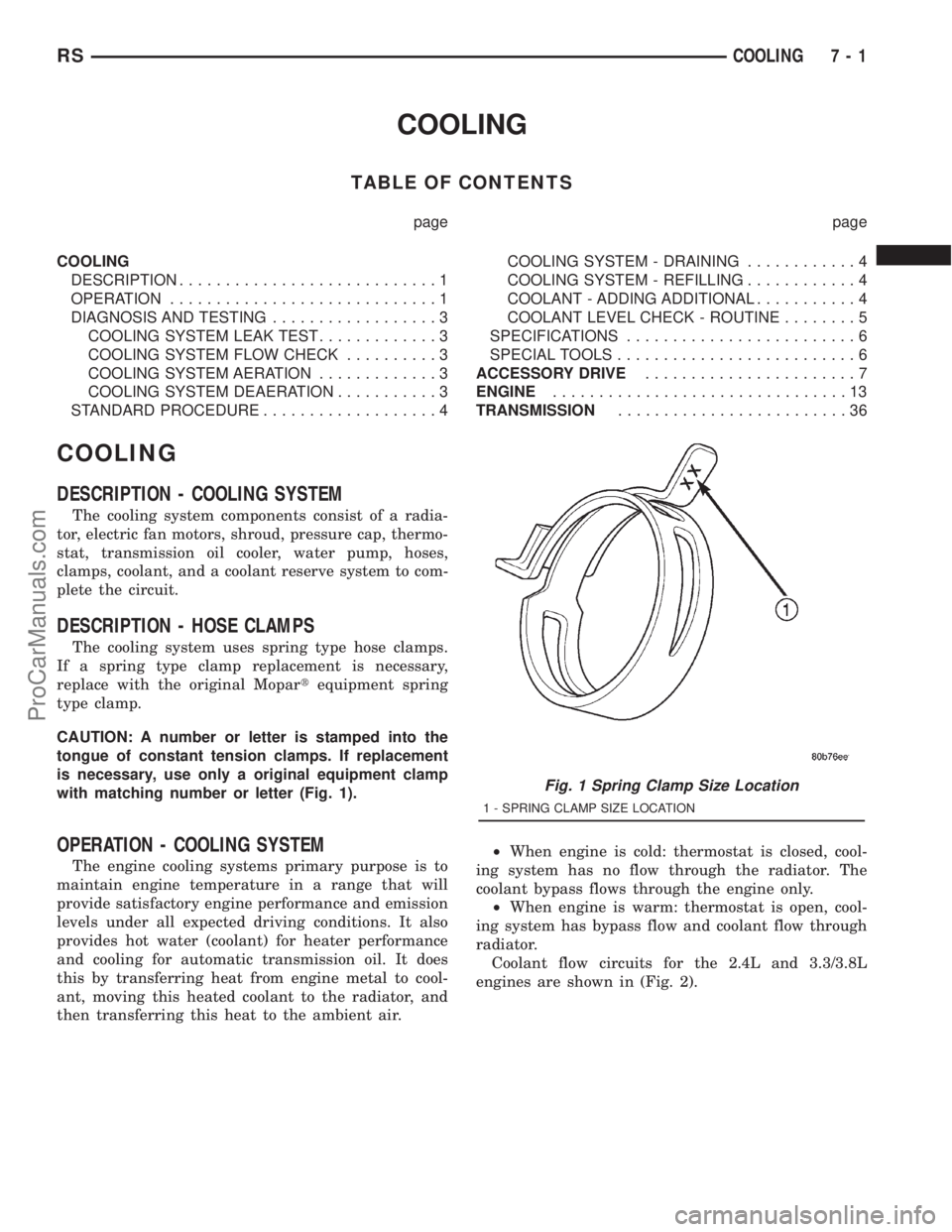
CAUTION: A number or letter is stamped into the
tongue of constant tension clamps. If replacement
is necessary, use only a original equipment clamp
with matching number or letter (Fig. 1).
OPERATION - COOLING SYSTEM
The engine cooling systems primary purpose is to
maintain engine temperature in a range that will
provide satisfactory engine performance and emission
levels under all expected driving conditions. It also
provides hot water (coolant) for heater performance
and cooling for automatic transmission oil. It does
this by transferring heat from engine metal to cool-
ant, moving this heated coolant to the radiator, and
then transferring this heat to the ambient air.²When engine is cold: thermostat is closed, cool-
ing system has no flow through the radiator. The
coolant bypass flows through the engine only.
²When engine is warm: thermostat is open, cool-
ing system has bypass flow and coolant flow through
radiator.
Coolant flow circuits for the 2.4L and 3.3/3.8L
engines are shown in (Fig. 2).
Fig. 1 Spring Clamp Size Location
1 - SPRING CLAMP SIZE LOCATION
RSCOOLING7-1
ProCarManuals.com
Page 296 of 2321
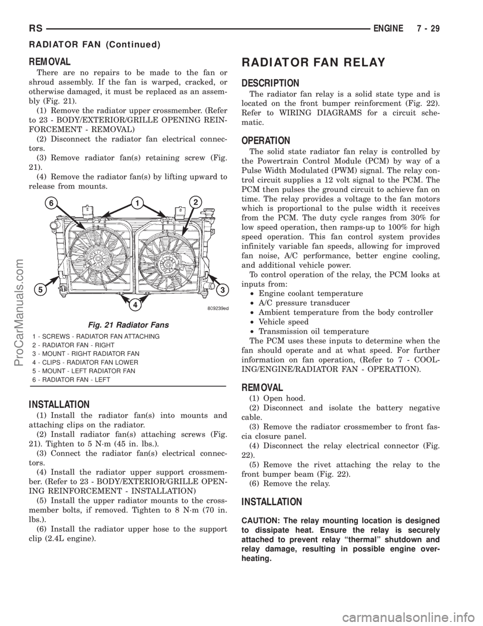
REMOVAL
There are no repairs to be made to the fan or
shroud assembly. If the fan is warped, cracked, or
otherwise damaged, it must be replaced as an assem-
bly (Fig. 21).
(1) Remove the radiator upper crossmember. (Refer
to 23 - BODY/EXTERIOR/GRILLE OPENING REIN-
FORCEMENT - REMOVAL)
(2) Disconnect the radiator fan electrical connec-
tors.
(3) Remove radiator fan(s) retaining screw (Fig.
21).
(4) Remove the radiator fan(s) by lifting upward to
release from mounts.
INSTALLATION
(1) Install the radiator fan(s) into mounts and
attaching clips on the radiator.
(2) Install radiator fan(s) attaching screws (Fig.
21). Tighten to 5 N´m (45 in. lbs.).
(3) Connect the radiator fan(s) electrical connec-
tors.
(4) Install the radiator upper support crossmem-
ber. (Refer to 23 - BODY/EXTERIOR/GRILLE OPEN-
ING REINFORCEMENT - INSTALLATION)
(5) Install the upper radiator mounts to the cross-
member bolts, if removed. Tighten to 8 N´m (70 in.
lbs.).
(6) Install the radiator upper hose to the support
clip (2.4L engine).
RADIATOR FAN RELAY
DESCRIPTION
The radiator fan relay is a solid state type and is
located on the front bumper reinforcment (Fig. 22).
Refer to WIRING DIAGRAMS for a circuit sche-
matic.
OPERATION
The solid state radiator fan relay is controlled by
the Powertrain Control Module (PCM) by way of a
Pulse Width Modulated (PWM) signal. The relay con-
trol circuit supplies a 12 volt signal to the PCM. The
PCM then pulses the ground circuit to achieve fan on
time. The relay provides a voltage to the fan motors
which is proportional to the pulse width it receives
from the PCM. The duty cycle ranges from 30% for
low speed operation, then ramps-up to 100% for high
speed operation. This fan control system provides
infinitely variable fan speeds, allowing for improved
fan noise, A/C performance, better engine cooling,
and additional vehicle power.
To control operation of the relay, the PCM looks at
inputs from:
²Engine coolant temperature
²A/C pressure transducer
²Ambient temperature from the body controller
²Vehicle speed
²Transmission oil temperature
The PCM uses these inputs to determine when the
fan should operate and at what speed. For further
information on fan operation, (Refer to 7 - COOL-
ING/ENGINE/RADIATOR FAN - OPERATION).
REMOVAL
(1) Open hood.
(2) Disconnect and isolate the battery negative
cable.
(3) Remove the radiator crossmember to front fas-
cia closure panel.
(4) Disconnect the relay electrical connector (Fig.
22).
(5) Remove the rivet attaching the relay to the
front bumper beam (Fig. 22).
(6) Remove the relay.
INSTALLATION
CAUTION: The relay mounting location is designed
to dissipate heat. Ensure the relay is securely
attached to prevent relay ªthermalº shutdown and
relay damage, resulting in possible engine over-
heating.
Fig. 21 Radiator Fans
1 - SCREWS - RADIATOR FAN ATTACHING
2 - RADIATOR FAN - RIGHT
3 - MOUNT - RIGHT RADIATOR FAN
4 - CLIPS - RADIATOR FAN LOWER
5 - MOUNT - LEFT RADIATOR FAN
6 - RADIATOR FAN - LEFT
RSENGINE7-29
RADIATOR FAN (Continued)
ProCarManuals.com