DODGE TOWN AND COUNTRY 2001 Service Manual
Manufacturer: DODGE, Model Year: 2001, Model line: TOWN AND COUNTRY, Model: DODGE TOWN AND COUNTRY 2001Pages: 2321, PDF Size: 68.09 MB
Page 2061 of 2321
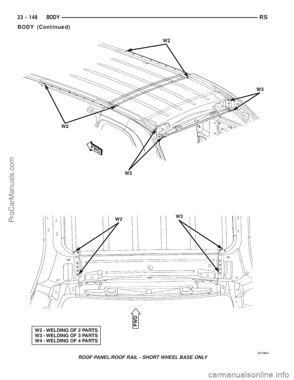
ROOF PANEL/ROOF RAIL - SHORT WHEEL BASE ONLY
23 - 148 BODYRS
BODY (Continued)
ProCarManuals.com
Page 2062 of 2321
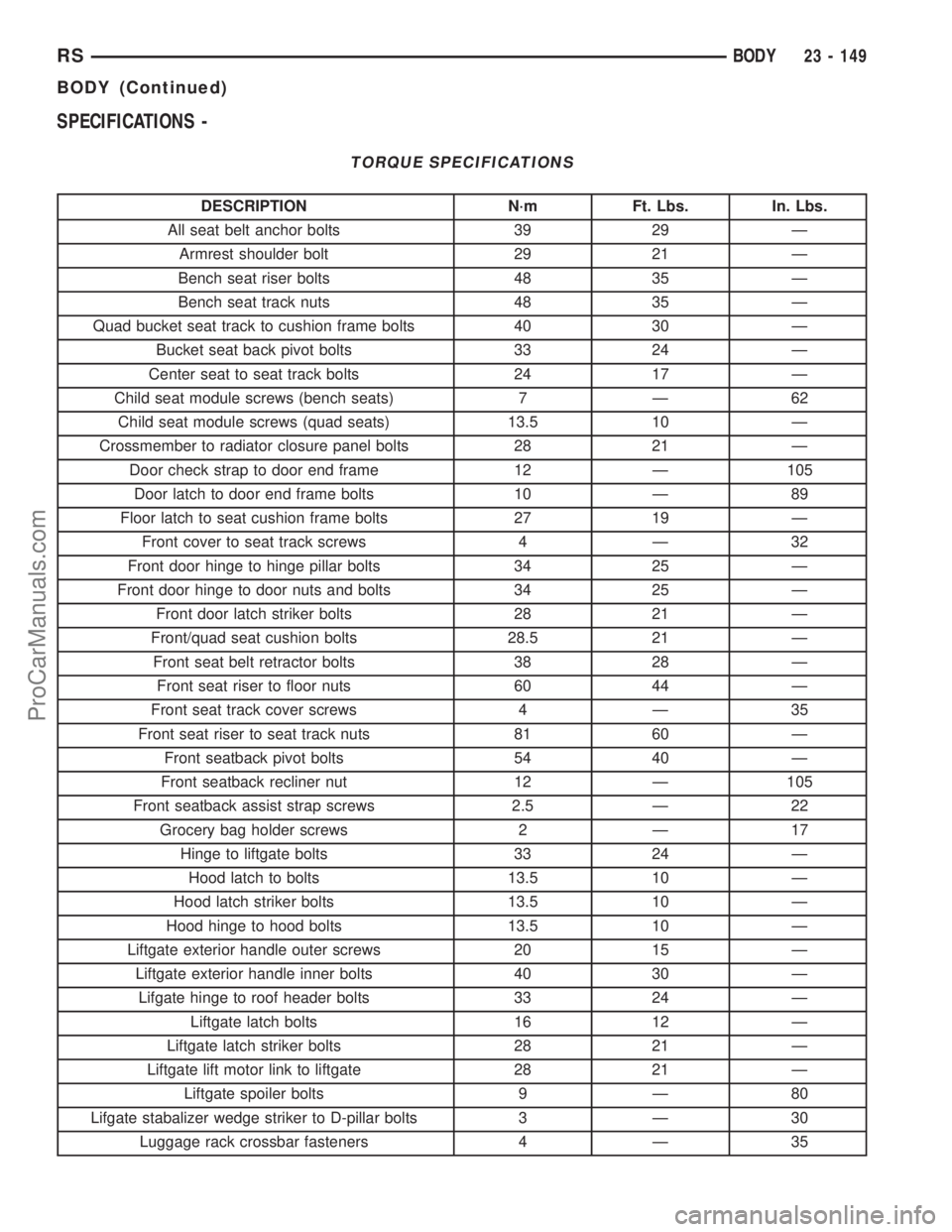
SPECIFICATIONS -
TORQUE SPECIFICATIONS
DESCRIPTION N´m Ft. Lbs. In. Lbs.
All seat belt anchor bolts 39 29 Ð
Armrest shoulder bolt 29 21 Ð
Bench seat riser bolts 48 35 Ð
Bench seat track nuts 48 35 Ð
Quad bucket seat track to cushion frame bolts 40 30 Ð
Bucket seat back pivot bolts 33 24 Ð
Center seat to seat track bolts 24 17 Ð
Child seat module screws (bench seats) 7 Ð 62
Child seat module screws (quad seats) 13.5 10 Ð
Crossmember to radiator closure panel bolts 28 21 Ð
Door check strap to door end frame 12 Ð 105
Door latch to door end frame bolts 10 Ð 89
Floor latch to seat cushion frame bolts 27 19 Ð
Front cover to seat track screws 4 Ð 32
Front door hinge to hinge pillar bolts 34 25 Ð
Front door hinge to door nuts and bolts 34 25 Ð
Front door latch striker bolts 28 21 Ð
Front/quad seat cushion bolts 28.5 21 Ð
Front seat belt retractor bolts 38 28 Ð
Front seat riser to floor nuts 60 44 Ð
Front seat track cover screws 4 Ð 35
Front seat riser to seat track nuts 81 60 Ð
Front seatback pivot bolts 54 40 Ð
Front seatback recliner nut 12 Ð 105
Front seatback assist strap screws 2.5 Ð 22
Grocery bag holder screws 2 Ð 17
Hinge to liftgate bolts 33 24 Ð
Hood latch to bolts 13.5 10 Ð
Hood latch striker bolts 13.5 10 Ð
Hood hinge to hood bolts 13.5 10 Ð
Liftgate exterior handle outer screws 20 15 Ð
Liftgate exterior handle inner bolts 40 30 Ð
Lifgate hinge to roof header bolts 33 24 Ð
Liftgate latch bolts 16 12 Ð
Liftgate latch striker bolts 28 21 Ð
Liftgate lift motor link to liftgate 28 21 Ð
Liftgate spoiler bolts 9 Ð 80
Lifgate stabalizer wedge striker to D-pillar bolts 3 Ð 30
Luggage rack crossbar fasteners 4 Ð 35
RSBODY23 - 149
BODY (Continued)
ProCarManuals.com
Page 2063 of 2321
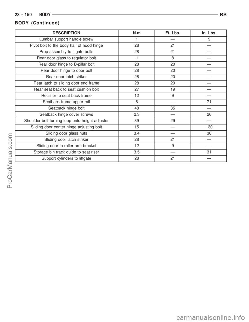
DESCRIPTION N´m Ft. Lbs. In. Lbs.
Lumbar support handle screw 1 Ð 9
Pivot bolt to the body half of hood hinge 28 21 Ð
Prop assembly to lifgate bolts 28 21 Ð
Rear door glass to regulator bolt 11 8 Ð
Rear door hinge to B-pillar bolt 28 20 Ð
Rear door hinge to door bolt 28 20 Ð
Rear door latch striker 28 20 Ð
Rear latch to sliding door end frame 28 20 Ð
Rear seat back to seat cushion bolt 27 19 Ð
Recliner to seat back frame 12 9 Ð
Seatback frame upper rail 8 Ð 71
Seatback hinge bolt 48 35 Ð
Seatback hinge cover screws 2.3 Ð 20
Shoulder belt turning loop onto height adjuster 39 29 Ð
Sliding door center hinge adjusting bolt 15 Ð 130
Sliding door glass nuts 3.4 Ð 30
Sliding door latch striker 28 21 Ð
Sliding door to roller arm bracket 12 9 Ð
Storage bin track quide to seat riser 3.5 Ð 31
Support cylinders to liftgate 28 21 Ð
23 - 150 BODYRS
BODY (Continued)
ProCarManuals.com
Page 2064 of 2321
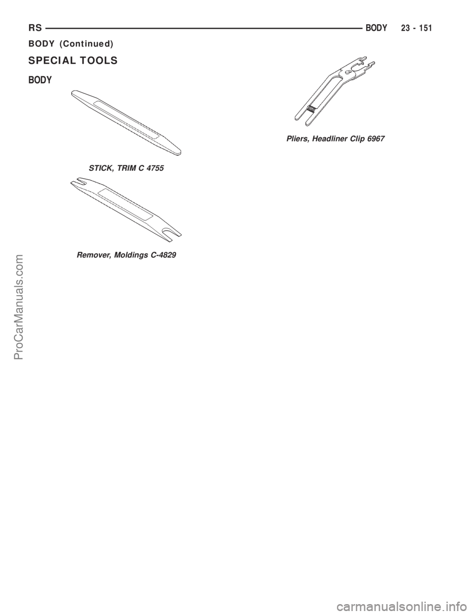
SPECIAL TOOLS
BODY
STICK, TRIM C 4755
Remover, Moldings C-4829
Pliers, Headliner Clip 6967
RSBODY23 - 151
BODY (Continued)
ProCarManuals.com
Page 2065 of 2321
DOOR - FRONT
TABLE OF CONTENTS
page page
APPLIQUE
REMOVAL.............................152
INSTALLATION..........................152
CHECK STRAP
REMOVAL.............................152
INSTALLATION..........................153
DOOR
REMOVAL.............................153
INSTALLATION..........................154
DOOR GLASS
REMOVAL.............................155
INSTALLATION..........................155
FRAME CLOSEOUT MOLDING
REMOVAL.............................155
INSTALLATION..........................156
HINGE
REMOVAL.............................156
INSTALLATION..........................156
LATCH
REMOVAL.............................156
INSTALLATION..........................157
LATCH STRIKER
REMOVAL.............................157INSTALLATION..........................157
LOCK CYLINDER
REMOVAL.............................157
INSTALLATION..........................157
TRIM PANEL
REMOVAL.............................158
INSTALLATION..........................158
TRIM PANEL REFLECTOR
REMOVAL.............................159
INSTALLATION..........................159
WATERSHIELD
REMOVAL.............................159
INSTALLATION..........................159
WINDOW CRANK
REMOVAL.............................159
INSTALLATION..........................159
WINDOW REGULATOR
REMOVAL.............................160
INSTALLATION..........................160
EXTERIOR HANDLE
REMOVAL.............................161
INSTALLATION..........................161
APPLIQUE
REMOVAL
(1) Roll door glass down.
(2) Remove outer door belt molding.
(3) Disengage clips holding front edge of applique
to door frame.
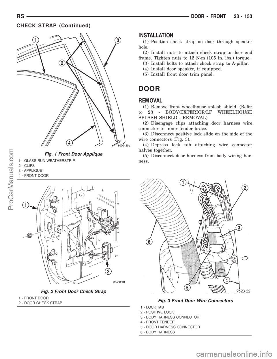
(4) Remove applique from vehicle (Fig. 1) .
INSTALLATION
(1) Position applique on vehicle.
(2)
Hook rear edge of applique over rear edge of door
frame and seat applique bottom edge on sheet metal.
(3) Engage clips to hold front edge of applique to
door frame.
(4) Install outer door belt molding.
CHECK STRAP
REMOVAL
(1) Remove front door watershield. (Refer to 23 -
BODY/DOOR - FRONT/WATERSHIELD -
REMOVAL)
(2) Remove bolts attaching door check strap to
A-pillar (Fig. 4).
(3) Remove nuts attaching check strap to door end
frame (Fig. 2).
(4) Remove check strap from door through speaker
hole.
23 - 152 DOOR - FRONTRS
ProCarManuals.com
Page 2066 of 2321
INSTALLATION
(1) Position check strap on door through speaker
hole.
(2) Install nuts to attach check strap to door end
frame. Tighten nuts to 12 N´m (105 in. lbs.) torque.
(3) Install bolts to attach check strap to A-pillar.
(4) Install door speaker, if equipped.
(5) Install front door trim panel.
DOOR
REMOVAL
(1) Remove front wheelhouse splash shield. (Refer
to 23 - BODY/EXTERIOR/LF WHEELHOUSE
SPLASH SHIELD - REMOVAL)
(2) Disengage clips attaching door harness wire
connector to inner fender brace.
(3) Disconnect positive lock slide on the side of the
wire connectors (Fig. 3).
(4) Depress lock tab attaching wire connector
halves together.
(5) Disconnect door harness from body wiring har-
ness.
Fig. 3 Front Door Wire Connectors
1 - LOCK TAB
2 - POSITIVE LOCK
3 - BODY HARNESS CONNECTOR
4 - FRONT FENDER
5 - DOOR HARNESS CONNECTOR
6 - BODY HARNESS
Fig. 1 Front Door Applique
1 - GLASS RUN WEATHERSTRIP
2 - CLIPS
3 - APPLIQUE
4 - FRONT DOOR
Fig. 2 Front Door Check Strap
1 - FRONT DOOR
2 - DOOR CHECK STRAP
RSDOOR - FRONT23 - 153
CHECK STRAP (Continued)
ProCarManuals.com
Page 2067 of 2321
(6) Remove bolts attaching door check strap to
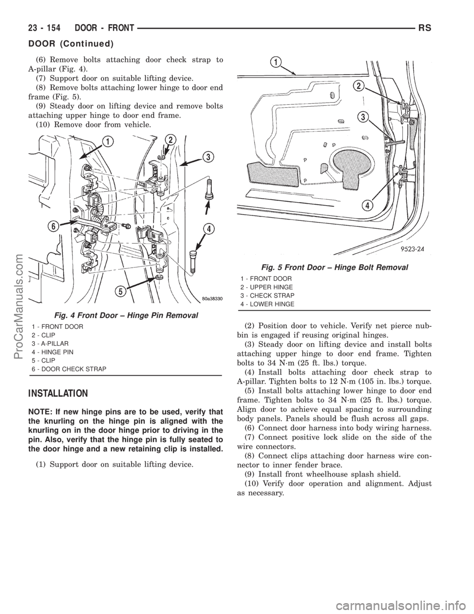
A-pillar (Fig. 4).
(7) Support door on suitable lifting device.
(8) Remove bolts attaching lower hinge to door end
frame (Fig. 5).
(9) Steady door on lifting device and remove bolts
attaching upper hinge to door end frame.
(10) Remove door from vehicle.
INSTALLATION
NOTE: If new hinge pins are to be used, verify that
the knurling on the hinge pin is aligned with the
knurling on in the door hinge prior to driving in the
pin. Also, verify that the hinge pin is fully seated to
the door hinge and a new retaining clip is installed.
(1) Support door on suitable lifting device.(2) Position door to vehicle. Verify net pierce nub-
bin is engaged if reusing original hinges.
(3) Steady door on lifting device and install bolts
attaching upper hinge to door end frame. Tighten
bolts to 34 N´m (25 ft. lbs.) torque.
(4) Install bolts attaching door check strap to
A-pillar. Tighten bolts to 12 N´m (105 in. lbs.) torque.
(5) Install bolts attaching lower hinge to door end
frame. Tighten bolts to 34 N´m (25 ft. lbs.) torque.
Align door to achieve equal spacing to surrounding
body panels. Panels should be flush across all gaps.
(6) Connect door harness into body wiring harness.
(7) Connect positive lock slide on the side of the
wire connectors.
(8) Connect clips attaching door harness wire con-
nector to inner fender brace.
(9) Install front wheelhouse splash shield.
(10) Verify door operation and alignment. Adjust
as necessary.
Fig. 4 Front Door ± Hinge Pin Removal
1 - FRONT DOOR
2 - CLIP
3 - A-PILLAR
4 - HINGE PIN
5 - CLIP
6 - DOOR CHECK STRAP
Fig. 5 Front Door ± Hinge Bolt Removal
1 - FRONT DOOR
2 - UPPER HINGE
3 - CHECK STRAP
4 - LOWER HINGE
23 - 154 DOOR - FRONTRS
DOOR (Continued)
ProCarManuals.com
Page 2068 of 2321
DOOR GLASS
REMOVAL
(1) Remove watershield. (Refer to 23 - BODY/
DOOR - FRONT/WATERSHIELD - REMOVAL)
(2) Remove inner belt molding.(Refer to 23 -
BODY/WEATHERSTRIP/SEALS/FDR INNER BELT
WEATHERSTRIP - REMOVAL)
(3) Remove outer belt molding.(Refer to 23 -
BODY/WEATHERSTRIP/SEALS/FDR OUTER BELT
MOLDING - REMOVAL)
(4) Position glass to gain access to front and rear
regulator lift plates through front and rear access
holes in door panel.
(5) Remove clips attaching door glass to regulator
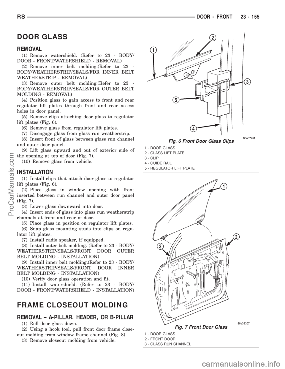
lift plates (Fig. 6).
(6) Remove glass from regulator lift plates.
(7) Disengage glass from glass run weatherstrip.
(8) Insert front of glass between glass run channel
and outer door panel.
(9) Lift glass upward and out of exterior side of
the opening at top of door (Fig. 7).
(10) Remove glass from vehicle.
INSTALLATION
(1) Install clips that attach door glass to regulator
lift plates (Fig. 6).
(2) Place glass in window opening with front
inserted between run channel and outer door panel
(Fig. 7).
(3) Lower glass downward into door.
(4) Insert ends of glass into glass run weatherstrip
channels at front and rear of door.
(5) Place glass in position on regulator lift plates.
(6) Snap glass mounting studs into clips on regu-
lator lift plates.
(7) Install radio speaker, if equipped.
(8) Install outer belt molding. (Refer to 23 - BODY/
WEATHERSTRIP/SEALS/FRONT DOOR OUTER
BELT MOLDING - INSTALLATION)
(9) Install inner belt molding.(Refer to 23 - BODY/
WEATHERSTRIP/SEALS/FRONT DOOR INNER
BELT MOLDING - INSTALLATION)
(10) Verify door glass operation and fit.
(11) Install watershield. (Refer to 23 - BODY/
DOOR - FRONT/WATERSHIELD - INSTALLATION)
FRAME CLOSEOUT MOLDING
REMOVAL ± A-PILLAR, HEADER, OR B-PILLAR
(1) Roll door glass down.
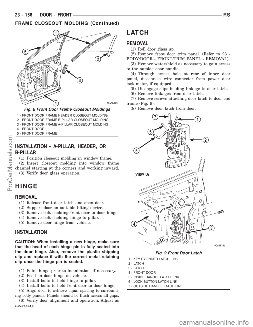
(2) Using a hook tool, pull front door frame close-
out molding from window frame channel (Fig. 8).
(3) Remove closeout molding from vehicle.
Fig. 6 Front Door Glass Clips
1 - DOOR GLASS
2 - GLASS LIFT PLATE
3 - CLIP
4 - GUIDE RAIL
5 - REGULATOR LIFT PLATE
Fig. 7 Front Door Glass
1 - DOOR GLASS
2 - FRONT DOOR
3 - GLASS RUN CHANNEL
RSDOOR - FRONT23 - 155
ProCarManuals.com
Page 2069 of 2321
INSTALLATION ± A-PILLAR, HEADER, OR
B-PILLAR
(1) Position closeout molding in window frame.
(2) Insert closeout molding into window frame
channel starting at the corners and working inward.
(3) Verify door glass operation.
HINGE
REMOVAL
(1) Release front door latch and open door.
(2) Support door on suitable lifting device.
(3) Remove bolts holding front door to door hinge.
(4) Remove bolts holding hinge to pillar.
(5) Remove door hinge from vehicle.
INSTALLATION
CAUTION: When installing a new hinge, make sure
that the head of each hinge pin is fully seated into
the door hinge. Also, remove the plastic shipping
clip and replace it with the correct metal retaining
clip once the hinge pin is seated.
(1) Paint hinge prior to installation, if necessary.
(2) Position door hinge on vehicle.
(3) Install bolts to hold hinge to pillar.
(4) Install bolts to hold front door to door hinge.
(5)
Align door to achieve equal spacing to surround-
ing body panels. Panels should be flush across all gaps.
(6) Verify door alignment and operation. Adjust as
necessary.
LATCH
REMOVAL
(1) Roll door glass up.
(2) Remove front door trim panel. (Refer to 23 -
BODY/DOOR - FRONT/TRIM PANEL - REMOVAL)
(3) Remove watershield as necessary to gain access
to the outside door handle.
(4) Through access hole at rear of inner door
panel, disconnect wire connector from power door
lock motor, if equipped.
(5) Disengage clips holding linkage to door latch.
(6) Remove linkages from door latch.
(7) Remove screws attaching door latch to door end
frame (Fig. 9).
(8) Remove door latch from door.
Fig. 8 Front Door Frame Closeout Moldings
1 - FRONT DOOR FRAME HEADER CLOSEOUT MOLDING
2 - FRONT DOOR FRAME B-PILLAR CLOSEOUT MOLDING
3 - FRONT DOOR FRAME A-PILLAR CLOSEOUT MOLDING
4 - FRONT DOOR
5 - FRONT DOOR FRAME
Fig. 9 Front Door Latch
1 - KEY CYLINDER LATCH LINK
2-LATCH
3-LATCH
4 - FRONT DOOR
5 - INSIDE HANDLE LATCH LINK
6 - LOCK BUTTON LATCH LINK
7 - OUTSIDE HANDLE LATCH LINK
23 - 156 DOOR - FRONTRS
FRAME CLOSEOUT MOLDING (Continued)
ProCarManuals.com
Page 2070 of 2321
INSTALLATION
NOTE: The screws attaching the door latch to the
door end frame have nylon patches on the threads.
All screws must be replaced when the latch has
been removed.
(1) Place door latch in position on door end frame.
(2) Install screws attaching door latch to door end
frame. Tighten screws to 10 N´m (90 in. lbs.) torque.
(3) Insert linkage into door latch.
(4) Engage clips attaching linkage to door latch.
(5) Connect wire connector into power door lock
motor, if equipped.
(6) Insert a hex wrench through the elongated hole
located in the door shut face above the latch.
(7) Loosen allen head screw.
(8) Pull outward on the outside door handle and
release.
(9) Tighten allen head screw.
(10)
Verify door latch and power door lock operation.
(11) Install watershield and front door trim panel.
LATCH STRIKER
REMOVAL
(1) Mark outline of door striker on B-pillar to aid
in installation.
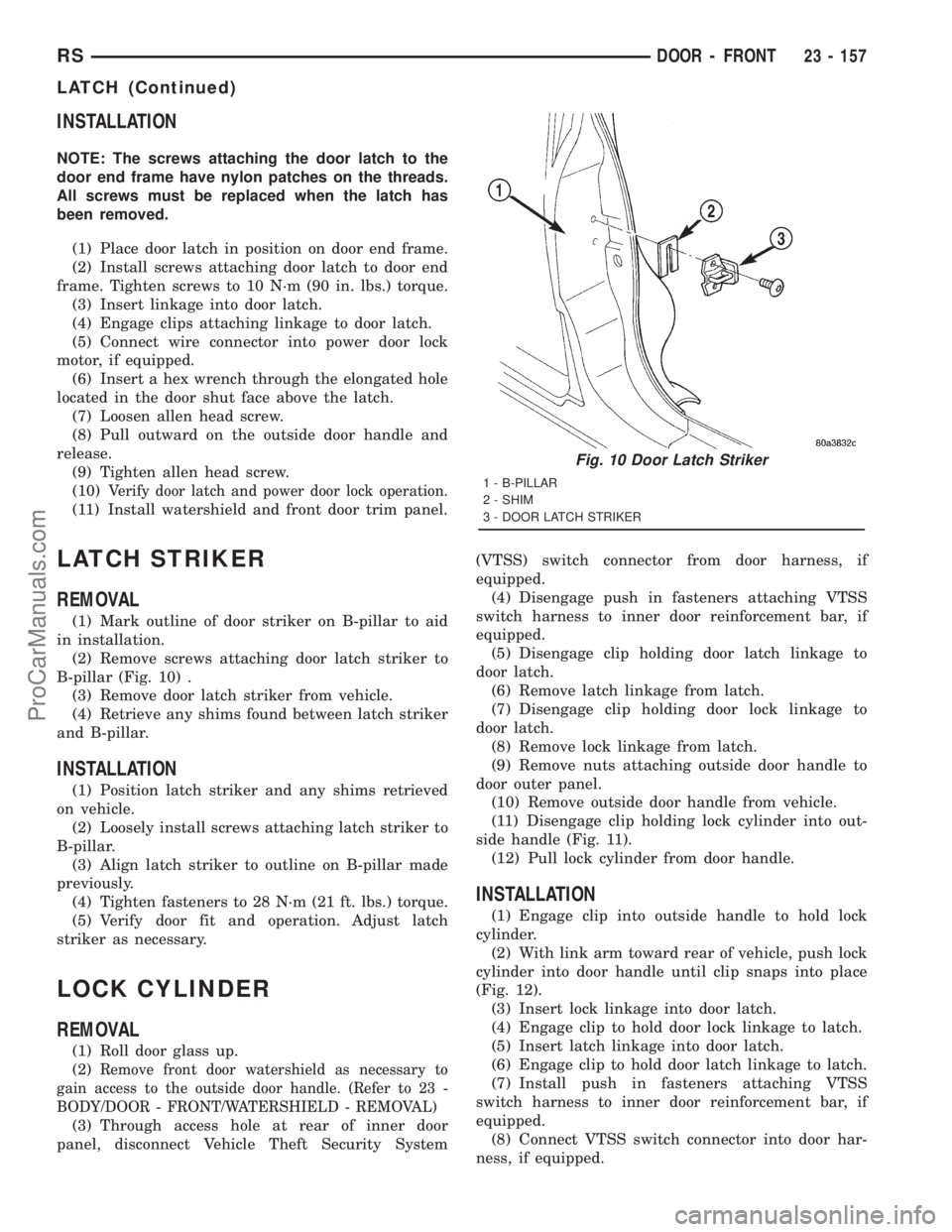
(2) Remove screws attaching door latch striker to
B-pillar (Fig. 10) .
(3) Remove door latch striker from vehicle.
(4) Retrieve any shims found between latch striker
and B-pillar.
INSTALLATION
(1) Position latch striker and any shims retrieved
on vehicle.
(2) Loosely install screws attaching latch striker to
B-pillar.
(3) Align latch striker to outline on B-pillar made
previously.
(4) Tighten fasteners to 28 N´m (21 ft. lbs.) torque.
(5) Verify door fit and operation. Adjust latch
striker as necessary.
LOCK CYLINDER
REMOVAL
(1) Roll door glass up.
(2)
Remove front door watershield as necessary to
gain access to the outside door handle. (Refer to 23 -
BODY/DOOR - FRONT/WATERSHIELD - REMOVAL)
(3) Through access hole at rear of inner door
panel, disconnect Vehicle Theft Security System(VTSS) switch connector from door harness, if
equipped.
(4) Disengage push in fasteners attaching VTSS
switch harness to inner door reinforcement bar, if
equipped.
(5) Disengage clip holding door latch linkage to
door latch.
(6) Remove latch linkage from latch.
(7) Disengage clip holding door lock linkage to
door latch.
(8) Remove lock linkage from latch.
(9) Remove nuts attaching outside door handle to
door outer panel.
(10) Remove outside door handle from vehicle.
(11) Disengage clip holding lock cylinder into out-
side handle (Fig. 11).
(12) Pull lock cylinder from door handle.
INSTALLATION
(1) Engage clip into outside handle to hold lock
cylinder.
(2) With link arm toward rear of vehicle, push lock
cylinder into door handle until clip snaps into place
(Fig. 12).
(3) Insert lock linkage into door latch.
(4) Engage clip to hold door lock linkage to latch.
(5) Insert latch linkage into door latch.
(6) Engage clip to hold door latch linkage to latch.
(7) Install push in fasteners attaching VTSS
switch harness to inner door reinforcement bar, if
equipped.
(8) Connect VTSS switch connector into door har-
ness, if equipped.
Fig. 10 Door Latch Striker
1 - B-PILLAR
2 - SHIM
3 - DOOR LATCH STRIKER
RSDOOR - FRONT23 - 157
LATCH (Continued)
ProCarManuals.com