fog light DODGE TOWN AND COUNTRY 2001 Owner's Manual
[x] Cancel search | Manufacturer: DODGE, Model Year: 2001, Model line: TOWN AND COUNTRY, Model: DODGE TOWN AND COUNTRY 2001Pages: 2321, PDF Size: 68.09 MB
Page 636 of 2321
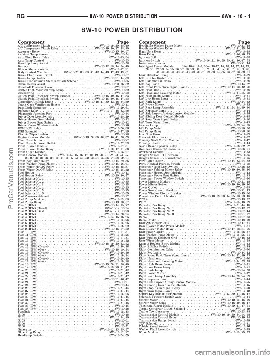
8W-10 POWER DISTRIBUTION
Component PageA/C Compressor Clutch..................8Wa-10-19, 20, 38, 40
A/C Compressor Clutch Relay.............8Wa-10-19, 20, 37, 38, 40
Accessory Relay.......................8Wa-10-15, 26, 57
Ambient Temp Sensor........................8Wa-10-54
Auto Shut Down Relay......................8Wa-10-19, 34
Auto Temp Control.........................8Wa-10-33
Back-Up Lamp Switch........................8Wa-10-58
Battery........................8Wa-10-12, 13, 14, 34, 40
Blower Motor Resistor......................8Wa-10-17, 31
Body Control Module......8Wa-10-21, 33, 38, 41, 42, 44, 46, 47, 48, 49, 61
Brake Fluid Level Switch......................8Wa-10-57
Brake Lamp Switch.....................8Wa-10-21, 44, 59
Brake Transmission Shift Interlock Solenoid.............8Wa-10-55
Cabin Heater Assist.....................8Wa-10-20, 36, 52
Camshaft Position Sensor......................8Wa-10-37
Center High Mounted Stop Lamp..................8Wa-10-59
Clockspring.............................8Wa-10-53
Clutch Pedal Interlock Switch Jumper........8Wa-10-16, 30, 46, 47, 53
Clutch Pedal Interlock Switch............8Wa-10-16, 30, 46, 47, 53
Controller Antilock Brake...........8Wa-10-16, 21, 30, 42, 48, 54, 59
Crank Case Ventilation Heater...................8Wa-10-41
Data Link Connector.......................8Wa-10-29, 61
Defogger Relay......................8Wa-10-17, 18, 32, 56
Diagnostic Junction Port.......................8Wa-10-54
Driver Door Lock Switch.....................8Wa-10-28, 29
Driver Heated Seat Module.....................8Wa-10-42
Driver Power Seat Switch......................8Wa-10-42
Driver Power Window Switch....................8Wa-10-29
ECM/PCM Relay.........................8Wa-10-20, 36
EGR Solenoid..........................8Wa-10-37, 39
Electric Wiper De-Icer........................8Wa-10-28
Engine Control Module........8Wa-10-16, 20, 30, 36, 37, 40, 41, 58, 59
Floor Console Lamp.........................8Wa-10-27
Floor Console Power Outlet...................8Wa-10-27, 29
Front Blower Module......................8Wa-10-17, 31
Front Blower Motor Relay................8Wa-10-16, 17, 31, 56
Front Cigar Lighter.......................8Wa-10-15, 27
Front Control Module . . . 8Wa-10-14, 15, 16, 17, 18, 19, 20, 21, 22, 23, 24, 25,
26, 29, 30, 31, 32, 38, 40, 45, 46, 47, 50, 51, 52, 53, 54. 55, 56, 57, 58, 59, 61
Front Fog Lamp Relay....................8Wa-10-14, 22, 56
Front Washer Pump Motor..................8Wa-10-15, 26, 61
Front Wiper Hi/Low Relay..................8Wa-10-15, 25, 57
Front Wiper On/Off Relay..................8Wa-10-15, 25, 52
Fuel Heater.............................8Wa-10-41
Fuel Heater Relay......................8Wa-10-20, 40, 57
Fuel Injector No. 1..........................8Wa-10-35
Fuel Injector No. 2..........................8Wa-10-35
Fuel Injector No. 3..........................8Wa-10-35
Fuel Injector No. 4..........................8Wa-10-35
Fuel Injector No. 5..........................8Wa-10-35
Fuel Injector No. 6..........................8Wa-10-35
Fuel Pressure Solenoid.......................8Wa-10-37
Fuel Pump Module........................8Wa-10-19, 38
Fuel Pump Relay.......................8Wa-10-19, 38, 57
Fuse 1 (IPM).........................8Wa-10-14, 15, 22
Fuse 2 (IPM) (Diesel).....................8Wa-10-14, 10-24
Fuse 2 (IPM) (Gas)......................8Wa-10-14, 10-23
Fuse 3 (IPM).........................8Wa-10-14, 23, 24
Fuse 4 (IPM).......................8Wa-10-14, 15, 16, 25
Fuse 5 (IPM)...........................8Wa-10-15, 26
Fuse 6 (IPM)...........................8Wa-10-15, 26
Fuse 8 (IPM)...........................8Wa-10-16, 29
Fuse 9 (IPM).........................8Wa-10-16, 17, 30
Fuse 10 (IPM)..........................8Wa-10-17, 31
Fuse 11 (IPM)..........................8Wa-10-15, 26
Fuse 12 (IPM)..........................8Wa-10-17, 31
Fuse 13 (IPM)..........................8Wa-10-18, 32
Fuse 14 (IPM)....................8Wa-10-18, 19, 20, 32, 52
Fuse 15 (IPM) (Diesel)......................8Wa-10-20, 36
Fuse 15 (IPM) (Gas).....................8Wa-10-18, 19, 34
Fuse 16 (IPM) (Diesel)......................8Wa-10-20, 36
Fuse 16 (IPM) (Gas).......................8Wa-10-19, 34
Fuse 17 (IPM) (Diesel)......................8Wa-10-20, 40
Fuse 17 (IPM) (Gas).......................8Wa-10-19, 38
Fuse 18 (IPM)....................8Wa-10-19, 20, 21, 38, 40
Fuse 19 (IPM)......................8Wa-10-19, 20, 21, 42
Fuse 20 (IPM)..........................8Wa-10-21, 42
Fuse 21 (IPM)..........................8Wa-10-21, 42
Fuse 22 (IPM)..........................8Wa-10-21, 42
Fuse 23 (IPM)........................8Wa-10-21, 46, 47
Fuse 24 (IPM)............................8Wa-10-21
Fuse 24 (IPM)............................8Wa-10-44
Fuse 26 (IPM)..........................8Wa-10-21, 44
Fuse 27 (IPM)..........................8Wa-10-21, 44
Fuse 28 (IPM)..........................8Wa-10-15, 26
Fuse 30 (IPM)..........................8Wa-10-21, 45
Fuse 31 (IPM)..........................8Wa-10-21, 45
Fuse 32 (IPM)..........................8Wa-10-21, 45
Fuse 33 (IPM)............................8Wa-10-15
Fuse 33 (IPM)............................8Wa-10-26
Fuselink.............................8Wa-10-12, 13
G100................................8Wa-10-48
G101...............................8Wa-10-34, 40
G103................................8Wa-10-61
G300................................8Wa-10-50
G300................................8Wa-10-51
Generator........................8Wa-10-12, 13, 35, 37
Glow Plug Relay.........................8Wa-10-12, 37
Headlamp Switch........................8Wa-10-24, 55Component PageHeadlamp Washer Pump Motor.................8Wa-10-21, 45
Headlamp Washer Relay...................8Wa-10-21, 45, 56
High Note Horn...........................8Wa-10-29
Horn Relay..........................8Wa-10-16, 29, 52
Ignition Coil.............................8Wa-10-35
Ignition Switch............8Wa-10-16, 21, 30, 38, 39, 41, 46, 47, 53
Instrument Cluster.......................8Wa-10-21, 44
Intelligent Power Module . . 8Wa-10-2, 10-3, 10-4, 10-12, 14, 15, 16, 17, 18, 19,
20, 21, 22, 23, 24, 25, 26, 27, 28, 29, 30, 31, 32, 33, 34, 35, 36, 37, 38, 39, 40,
41, 42, 44, 45, 46, 47, 48, 49, 50, 51, 52, 53, 54, 55, 56, 57, 58, 59, 61
Leak Detection Pump........................8Wa-10-39
Left B-Pillar Switch.........................8Wa-10-28
Left Combination Relay.......................8Wa-10-60
Left Fog Lamp..........................8Wa-10-14, 22
Left Front Park/ Turn Signal Lamp............8Wa-10-14, 23, 49, 58
Left Headlamp............................8Wa-10-50
Left Headlamp Leveling Motor................8Wa-10-24, 55, 58
Left High Beam Lamp........................8Wa-10-51
Left Low Beam Lamp........................8Wa-10-51
Left Park Lamp.........................8Wa-10-24, 58
Left Power Mirror..........................8Wa-10-32
Left Rear Lamp Assembly..............8Wa-10-23, 24, 58, 59, 60
Left Repeater Lamp.........................8Wa-10-44
Left Side Impact Airbag Control Module...............8Wa-10-55
Left Sliding Door Control Module..................8Wa-10-45
Left Stop/ Turn Signal Relay.....................8Wa-10-60
Left Turn Signal Lamp.......................8Wa-10-49
License Lamp........................8Wa-10-23, 24, 58
Lift Pump Motor.........................8Wa-10-20, 36
Lift Pump Relay.........................8Wa-10-20, 36
Low Note Horn...........................8Wa-10-29
Mass Air Flow Sensor........................8Wa-10-37
Memory Seat/ Mirror Module....................8Wa-10-42
Message Center...........................8Wa-10-44
Name Brand Speaker Relay.................8Wa-10-18, 32, 52
Occupant Restraint Controller..................8Wa-10-56, 61
Overhead Console..........................8Wa-10-33
Oxygen Sensor 1/1 Upstream....................8Wa-10-35
Oxygen Sensor 1/2 Downstream...................8Wa-10-35
Park Lamp Relay.....................8Wa-10-14, 23, 24, 52
Park/ Neutral Position Switch....................8Wa-10-58
Passenger Door Lock Switch...................8Wa-10-26, 28
Passenger Folding Mirror Relay.............8Wa-10-19, 20, 38, 40
Passenger Heated Seat Module...................8Wa-10-43
Passenger Power Seat Switch....................8Wa-10-43
Passenger Power Window Switch..................8Wa-10-26
Power Liftgate Module......................8Wa-10-21, 45
Power Mirror Switch...................8Wa-10-19, 20, 39, 40
Power Outlet............................8Wa-10-29
Power Seat Circuit Breaker...................8Wa-10-21, 42
Power Window Circuit Breaker.................8Wa-10-15, 26
Powertrain Control Module........8Wa-10-16, 19, 30, 34, 35, 38, 39, 48
PTC4 ..............................8Wa-10-18, 32
Ptc7.............................8Wa-10-15, 16, 29
Radiator Fan Relay.....................8Wa-10-21, 44, 48
Radiator Fan Relay No. 1....................8Wa-10-12, 37
Radiator Fan Relay No. 2....................8Wa-10-37, 44
Radiator Fan Relay No. 3....................8Wa-10-21, 37
Radio..............................8Wa-10-27, 33
Radio Choke...........................8Wa-10-18, 32
Rear A/C-Heater Unit......................8Wa-10-17, 31
Rear Blower Motor Power Module..................8Wa-10-31
Rear Blower Motor Relay.................8Wa-10-17, 18, 31, 56
Rear Power Outlet......................8Wa-10-15, 26, 27
Rear Washer Pump Motor..................8Wa-10-15, 26, 61
Rear Window Defogger Grid...................8Wa-10-18, 32
Rear Wiper Motor..........................8Wa-10-28
Remote Keyless Entry Module....................8Wa-10-33
Right B-Pillar Switch........................8Wa-10-28
Right Combination Relay......................8Wa-10-60
Right Fog Lamp.........................8Wa-10-14, 22
Right Front Park/ Turn Signal Lamp...........8Wa-10-14, 23, 49, 53
Right Headlamp...........................8Wa-10-50
Right Headlamp Leveling Motor...............8Wa-10-24, 53, 55
Right High Beam Lamp.......................8Wa-10-51
Right Low Beam Lamp.......................8Wa-10-51
Right Park Lamp........................8Wa-10-24, 53
Right Power Mirror.........................8Wa-10-32
Right Rear Lamp Assembly................8Wa-10-14, 23, 24, 59
Right Repeater Lamp........................8Wa-10-44
Right Side Impact Airbag Control Module..............8Wa-10-55
Right Sliding Door Control Module.................8Wa-10-45
Right Stop/ Turn Signal Relay....................8Wa-10-60
Right Turn Signal Lamp.......................8Wa-10-49
Sentry Key Immobilizer Module...........8Wa-10-33, 39, 41, 46, 47
Solenoid/ Pressure Switch Assy...................8Wa-10-34
Starter Motor.......................8Wa-10-12, 13, 16, 30
Starter Motor Relay...................8Wa-10-16, 30, 46, 47
Thatcham Alarm Module.................8Wa-10-39, 41, 47, 61
Torque Converter Clutch Solenoid..................8Wa-10-39
Trailer Tow Connector......................8Wa-10-23, 58
Transmission Control Module...........8Wa-10-16, 19, 30, 34, 54, 55
Transmission Control Relay...................8Wa-10-19, 34
Transmission Range Sensor.....................8Wa-10-58
TXV Solenoid............................8Wa-10-31
Vehicle Speed Sensor........................8Wa-10-36
Washer Fluid Level Switch.....................8Wa-10-53
Wiper Module........................8Wa-10-15, 25, 52
RG8W-10 POWER DISTRIBUTION8Wa-10-1
ProCarManuals.com
Page 698 of 2321
8W-15 GROUND DISTRIBUTION
Component PageA/C Compressor Clutch...................8Wa-15-6, 7
A/C-Heater Control....................8Wa-15-8, 10
Auto Temp Control.......................8Wa-15-8
Automatic Day/Night Mirror................8Wa-15-18
Autostick Switch........................8Wa-15-9
Back-Up Lamp Switch...................8Wa-15-3, 6
Battery............................8Wa-15-2, 3
Body Control Module.....................8Wa-15-19
Brake Fluid Level Switch..................8Wa-15-14
Brake Lamp Switch......................8Wa-15-14
Cabin Heater Assist......................8Wa-15-7
Center Dome Lamp......................8Wa-15-18
Center High Mounted Stop Lamp.............8Wa-15-23
Clockspring...........................8Wa-15-9
Clutch Pedal Upstop Switch.................8Wa-15-15
Controller Antilock Brake.................8Wa-15-2, 3
Crank Case Ventilation Heater................8Wa-15-7
Crankshaft Position Sensor..................8Wa-15-3
Data Link Connector..................8Wa-15-2, 3, 14
Dosing Pump..........................8Wa-15-7
Driver Door Courtesy Lamp..............8Wa-15-13, 17
Driver Door Lock Switch................8Wa-15-13, 17
Driver Heated Seat Cushion................8Wa-15-10
Driver Heated Seat Module.................8Wa-15-10
Driver Power Seat Switch..................8Wa-15-10
Driver Power Window Switch..............8Wa-15-13, 17
Engine Control Module....................8Wa-15-3
Floor Console Lamp......................8Wa-15-22
Floor Console Power Outlet.................8Wa-15-22
Front Blower Module.....................8Wa-15-10
Front Cigar Lighter......................8Wa-15-8
Front Control Module.................8Wa-15-6, 7, 15
Front Reading Lamps/ Switch...............8Wa-15-18
Fuel Heater..........................8Wa-15-22
Fuel Heater Relay.......................8Wa-15-3
Fuel Pump Module......................8Wa-15-22
G100...............................8Wa-15-2
G100...............................8Wa-15-3
G101..............................8Wa-15-2, 3
G102..............................8Wa-15-4, 5
G103..............................8Wa-15-6, 7
G200............................8Wa-15-8, 9, 10
G201...............................8Wa-15-11
G300........................8Wa-15-12, 13, 14, 15
G301........................8Wa-15-16, 17, 18, 19
G302............................8Wa-15-20, 21
G302...............................8Wa-15-22
G400............................8Wa-15-22, 23
Glove Box Lamp........................8Wa-15-9
Halo Lamp............................8Wa-15-9
Headlamp Switch........................8Wa-15-8
Headlamp Washer Pump Motor...............8Wa-15-5
High Note Horn.........................8Wa-15-5
Hood Ajar Switch.......................8Wa-15-15
Instrument Cluster.......................8Wa-15-8
Instrument Panel Switch Bank...............8Wa-15-9
Intelligent Power Module............8Wa-15-2, 3, 6, 7, 15
Left B-Pillar Switch......................8Wa-15-14
Left Cinch/ Release Motor..................8Wa-15-12
Left Combination Relay...................8Wa-15-21
Left Cylinder Lock Switch..................8Wa-15-13
Left Fog Lamp..........................8Wa-15-5
Left Front Door Ajar Switch.................8Wa-15-13
Left Front Door Lock Motor/ Ajar Switch.........8Wa-15-13
Left Front Park/ Turn Signal Lamp.............8Wa-15-5
Left Full Open Switch....................8Wa-15-12
Left Headlamp.........................8Wa-15-15
Left Headlamp Leveling Motor................8Wa-15-5
Left High Beam Lamp....................8Wa-15-15
Left Liftgate Flood Lamp..................8Wa-15-23
Left Low Beam Lamp.....................8Wa-15-15
Left Mid Reading Lamp...................8Wa-15-18
Left Park Lamp........................8Wa-15-15
Left Power Mirror.......................8Wa-15-9
Left Rear Lamp Assembly..................8Wa-15-21
Left Rear Reading Lamp...................8Wa-15-18
Left Side Impact Airbag Control Module.........8Wa-15-11
Left Sliding Door Control Module.............8Wa-15-12
Left Sliding Door Latch Sensing Switch.........8Wa-15-12
Left Sliding Door Lock Motor................8Wa-15-12Component PageLeft Sliding Door Lock Motor/ Ajar Switch........8Wa-15-12
Left Sliding Door Motor...................8Wa-15-12
Left Stop/ Turn Signal Relay................8Wa-15-21
Left Turn Signal Lamp....................8Wa-15-15
Left Visor/ Vanity Lamp...................8Wa-15-18
License Lamp.......................8Wa-15-20, 23
Lift Pump Motor........................8Wa-15-22
Liftgate Ajar Switch.....................8Wa-15-23
Liftgate Cinch/ Release Motor................8Wa-15-20
Liftgate Cylinder Lock Switch...............8Wa-15-23
Liftgate Right Pinch Sensor.................8Wa-15-20
Low Note Horn.........................8Wa-15-5
Memory Power Seat Switch.................8Wa-15-10
Memory Seat/ Mirror Module................8Wa-15-10
Occupant Restraint Controller...............8Wa-15-11
Overhead Console.......................8Wa-15-18
Oxygen Sensor 1/2 Downstream...............8Wa-15-6
Park/ Neutral Position Switch................8Wa-15-6
Passenger Door Courtesy Lamp............8Wa-15-13, 17
Passenger Door Lock Switch..............8Wa-15-13, 17
Passenger Heated Seat Module...............8Wa-15-19
Passenger Power Seat Switch................8Wa-15-19
Passenger Power Window Switch...........8Wa-15-13, 17
Power Folding Mirror Switch................8Wa-15-10
Power Liftgate Module....................8Wa-15-20
Power Liftgate Motor.....................8Wa-15-20
Power Mirror Switch.....................8Wa-15-10
Power Outlet..........................8Wa-15-8
Powertrain Control Module..................8Wa-15-2
Radiator Fan No. 1.......................8Wa-15-4
Radiator Fan No. 2.......................8Wa-15-4
Radiator Fan Relay.......................8Wa-15-4
Radiator Fan Relay No. 3...................8Wa-15-4
Rear Auto Temp Control Switch..............8Wa-15-14
Rear Blower Front Control Switch.............8Wa-15-10
Rear Blower Motor Power Module...........8Wa-15-10, 22
Rear Blower Rear Control Switch.............8Wa-15-14
Rear Dome Lamp.......................8Wa-15-18
Rear Power Outlet......................8Wa-15-22
Rear Window Defogger Grid.................8Wa-15-23
Rear Wiper Motor.......................8Wa-15-23
Remote Keyless Entry Module................8Wa-15-9
Right B-Pillar Switch.....................8Wa-15-19
Right Cinch/ Release Motor.................8Wa-15-16
Right Combination Relay..................8Wa-15-21
Right Cylinder Lock Switch.................8Wa-15-17
Right Fog Lamp.........................8Wa-15-5
Right Front Door Ajar Switch................8Wa-15-17
Right Front Door Lock Motor/ Ajar Switch........8Wa-15-17
Right Front Park/ Turn Signal Lamp............8Wa-15-5
Right Full Open Switch...................8Wa-15-16
Right Headlamp........................8Wa-15-15
Right Headlamp Leveling Motor...............8Wa-15-5
Right High Beam Lamp...................8Wa-15-15
Right Liftgate Flood Lamp.................8Wa-15-23
Right Low Beam Lamp....................8Wa-15-15
Right Mid Reading Lamp..................8Wa-15-18
Right Park Lamp.......................8Wa-15-15
Right Power Mirror.......................8Wa-15-9
Right Rear Lamp Assembly.................8Wa-15-22
Right Rear Reading Lamp..................8Wa-15-18
Right Side Impact Airbag Control Module........8Wa-15-11
Right Sliding Door Control Module............8Wa-15-16
Right Sliding Door Latch Sensing Switch.........8Wa-15-16
Right Sliding Door Lock Motor...............8Wa-15-16
Right Sliding Door Lock Motor/ Ajar Switch.......8Wa-15-16
Right Sliding Door Motor..................8Wa-15-16
Right Stop/ Turn Signal Relay...............8Wa-15-21
Right Turn Signal Lamp...................8Wa-15-15
Right Visor/ Vanity Lamp..................8Wa-15-18
Sentry Key Immobilizer Module...............8Wa-15-9
Speed Control Servo......................8Wa-15-6
Traction Control Switch....................8Wa-15-9
Trailer Tow Connector....................8Wa-15-21
Transmission Control Module................8Wa-15-2
Transmission Control Relay..................8Wa-15-2
Transmission Range Sensor..................8Wa-15-6
Washer Fluid Level Switch..................8Wa-15-5
Wiper Module.........................8Wa-15-14
RG8W-15 GROUND DISTRIBUTION8Wa-15-1
ProCarManuals.com
Page 890 of 2321

8W-50 FRONT LIGHTING
Component Page
Body Control Module............. 8Wa-50-2, 4, 5
Diagnostic Junction Port.......... 8Wa-50-5, 6, 8
Front Control Module . 8Wa-50-3, 4, 6, 7, 8, 9, 10, 11
Front Fog Lamp Relay.............. 8Wa-50-11
Fuse 1 (IPM)...................... 8Wa-50-11
Fuse 2 (IPM)..................... 8Wa-50-4, 6
Fuse 3 (IPM)..................... 8Wa-50-4, 8
G102........................ 8Wa-50-4, 8, 11
G200.......................... 8Wa-50-2, 10
G300............................. 8Wa-50-3
Headlamp Switch................ 8Wa-50-2, 10
Intelligent Power Module . 8Wa-50-3, 4, 5, 6, 7, 8, 9,
10, 11
Left Fog Lamp..................... 8Wa-50-11
Left Front Park/Turn Signal Lamp...... 8Wa-50-4
Left Headlamp..................... 8Wa-50-3
Left Headlamp Leveling Motor...... 8Wa-50-6, 10
Left High Beam Lamp.............. 8Wa-50-6, 7
Left Low Beam Lamp................ 8Wa-50-7
Left Park Lamp................... 8Wa-50-6, 7
Multi- Function Switch............... 8Wa-50-5
Park Lamp Relay............... 8Wa-50-4, 6, 8
Right Fog Lamp................... 8Wa-50-11
Right Front Park/Turn Signal Lamp..... 8Wa-50-4
Right Headlamp.................... 8Wa-50-3
Right Headlamp Leveling Motor..... 8Wa-50-8, 10
Right High Beam Lamp............ 8Wa-50-8, 9
Right Low Beam Lamp............... 8Wa-50-9
Right Park Lamp................. 8Wa-50-8, 9
RG8W-50 FRONT LIGHTING8Wa-50-1
ProCarManuals.com
Page 1395 of 2321

FRONT FASCIA
REMOVAL
(1) Release hood latch and open hood.
(2) Remove the headlamp assemblies. Refer to
group 8 exterior lighting.
(3) Remove two bolts attaching the upper grill sup-
port to the headlamp mounting panel at each side of
the grille.
(4) Hoist vehicle and support with safety stands.
(5)
Remove front wheels. Refer to Group 22, Wheels
and Tires, for proper procedures and sequence.
(6) Remove front wheelhouse splash shields fasten-
ers as necessary to gain access to bolts holding front
fascia to fender. Refer to Group 23, Body, for proper
procedures.
(7) Remove the two bolts and two nuts holding fas-
cia to the front fenders (Fig. 1).
(8) Remove the five bolts holding bottom of fascia/
air dam to radiator closure panel.
(9) Disconnect fog lamp/parking and turn signal
lamp wire connector, as necessary.
(10) Remove bumper fascia from vehicle.
INSTALLATION
(1) Position front bumper fascia on vehicle.
(2) Lower vehicle.
(3) Install the two bolts to hold fascia to headlamp
mounting panel at each side of grille.(4) Raise vehicle.
(5) Install the two bolts and two nuts to hold fas-
cia to the front fenders (Fig. 1). The fascia should be
flush to fender.
(6) Install front wheelhouse splash shields fasten-
ers. Refer to Group 23, Body, for proper procedures.
(7) Install front wheels. Refer to Group 22, Wheels
and Tires, for proper procedures and tightening
sequence.
(8) Install the five bolts to hold bottom of fascia to
radiator closure panel.
(9) Lower the vehicle.
(10) Install the headlamp assemblies. Refer to sec-
tion 8 for installation.
FRONT BUMPER
REINFORCEMENT
REMOVAL
(1) Remove front bumper fascia. (Refer to 13 -
FRAMES & BUMPERS/BUMPERS/FRONT FASCIA
- REMOVAL)
(2) Support front bumper reinforcement on a suit-
able lifting device.
(3) Remove the four nuts holding front bumper
reinforcement to frame rail (Fig. 2).
(4) Remove front bumper reinforcement from vehicle.
Fig. 1 FRONT BUMPER FASCIA
1 - FRONT BUMPER FASCIA
2 - FRONT BUMPER REINFORCEMENT
3 - RADIATOR ENCLOSURE
Fig. 2 FRT BUMPER REINFORCEMENT
1 - FRONT BUMPER REINFORCEMENT
2 - FRAME RAILS
13 - 2 FRAMES & BUMPERSRS
ProCarManuals.com
Page 2166 of 2321
²Rear window defogger on/off switch. A graphic
symbol shows when the defroster is on.
²An air conditioning button that allows the com-
pressor to be turned off. A Snowflake symbol is illu-
minated when air conditioning is on, whether under
manual or automatic control.
²Rotary knob for front fan speed selection can
override the automatic controls. LEDs surrounding
the knob show the current setting.
²Rotary knob for control of the Rear system.
²A rotary knob for mode control can override the
automatic controls. LEDs surrounding the knob show
the current setting.
²Computer logic remembers the settings of the
controls when the ignition is turned off and retains
those settings after a restart. If the system is off
when the ignition is turned of, it will be off when the
engine is restarted, etc.
²Computer logic provides variable air recircula-
tion under high temperature and humidity condi-
tions. Because recirculation is generally accompanied
by increased fan noise, the proportion of recirculated
to outside air gradually approaches full recirculation
over a broad temperature range.
²A graphic symbol of the windshield that illumi-
nates when the windshield wiper deicer is active.
REAR CONTROL PANEL
A rear control panel centrally mounted on the
headliner includes a vacuum-flourescent digital dis-
play, a rocker control for temperature and rotary con-
trols for adjustment of mode and fan speed control of
the rear unit by intermediate seat passengers.
OPERATION - DUAL ZONE
²The mode control knob enables continously vari-
able proportioning of air flow between modes but has
detents adjacent to each icon.
²The blower control provides five separate speeds.
²When the fan is off, the HVAC computer closes
the recirculation door to prevent outside air from
entering the passenger compartment.
²Interior air may be recirculated to speed up
heating or cooling in all modes exccept defrost and
mix by pressing the Recirculate button on the control
panel.
²To reduce humidity for rapid defogging the A/C
compressor runs automatically in modes from ªmix'
to full defrost when outside temperautres are above
freezing.
²Air conditioning is available in any mode by
pressing the snowflake, A/C on/off, button.
OPERATION - MANUAL THREE ZONE
FRONT CONTROL PANEL
²Primary control of the rear compartment unit is
on the instrument panel. This control allows the
driver to set the rear compartment fan speed, to turn
the rear unit off, or to give control to the intermedi-
ate seat occupants by switching to the REAR posi-
tion. When the rear unit is controlled from the
instrument panel, rear air temperature is based on
the driver-side temperature control position, and the
mode (floor or overhead air) is based on the front
control's mode position.
²The mode control knob enables continously vari-
able proportioning of air flow between modes but has
detents adjacent to each icon.
²The blower control provides five separate speeds
and Off. When the fan is off, the HVAC computer
closes the recirculation door to prevent outside air
from entering the passenger compartment.
²Interior air may be recirculated to speed up
heating or cooling in all modes exccept defrost and
mix by pressing the Recirculate button on the control
panel.
²To reduce humidity for rapid defogging the A/C
compressor runs automatically in modes from ªmix'
to full defrost when outside temperautres are above
freezing.
²Air conditioning is available in any mode by
pressing the snowflake, A/C on/off, button.
REAR CONTROL PANEL
With the rear control active, temperature selection
dictates indirectly the mode (floor or overhead air) of
the rear unit: a low temperature setting directs flow
to the overhead outlets and a high temperature set-
ting to the floor.
OPERATION - THREE ZONE ATC
Comfort temperature or perceived temperature is
affected by air flow, sun impinging on exposed skin,
etc. The air temperature may be higher or lower than
the comfort temperature. Three infrared sensors, two
in the instrument panel center stack, and one in the
overhead-mounted rear control panel, independently
measure the temperature of the driver, front passen-
ger, and rear compartment occupants to determine
their comfort level relative to the selected comfort
temperature. The HVAC computer in the control
module adjusts the air flow rate and temperature to
maintain the customer-perceived comfort tempera-
ture. The air temperature in the passenger compart-
ment at any time may be slightly higher or lower
than the comfort temperature. For instance, on
sunny summer days the air flow will probably be
cooler than the comfort temperature; on cold or
RSHEATING & AIR CONDITIONING24-3
HEATING & AIR CONDITIONING (Continued)
ProCarManuals.com
Page 2167 of 2321
cloudy days and at night it will probably be slightly
warmer. Infrared Three-Zone Temperature Control
provides side-to-side and front-to-rear variation in
comfort temperature settings. The Infrared Three-
Zone Automatic Temperature Control fan provides a
continuously variable air flow rate to meet occupant
comfort requirements.
FRONT CONTROL PANEL
²AUTO HI/LO± This system features two sets of
automatic control logic that allow either a rapid cool-
down rate or a somewhat slower cool-down rate with
less fan noise. HI-AUTO controls the system to reach
its assigned temperature quickly with a higher fan
speed. LO-AUTO controls the system to reach its
assigned temperature somewhat slower with less fan
noise. Both modes will automatically engage auto
recirculation.
²DE-FROST± The front de-frost function is
active when the rear window defogger function is
active or when the defog/defrost mode is selected.
²RECIRC± The RECIRC button will close the
air inlet door. If the system is in auto recirc (indica-
tor being displayed automatically), pressing the man-
ual recirc button will disable the auto recirc function
until one of the auto keys are pressed or the ignition
is cycled. If Auto HI/LO is pressed while manual
recirc is active, manual recirc will be deactivated.
²REAR WINDOW DEFOGGER± Pushing the
button sends a PCI bus message to the Intelligent
Power Module which controls the Rear Window
Defogger and side view mirror (if equipped) circuitry.
The defogger function will be active for 10 minutes
and can be turned off by a switch press. The defogger
will function while the control is in the OFF mode.
²FAN/MODE± The Fan and Mode knobs have
17 manual selectable positions. Manually changing
either of the rotary knobs for mode or fan speed set-
tings makes control of that function alone manual for
as long as the ignition is on. If only one is changed
manually, the other remains under automatic control.
Pressing the HI-AUTO/LO-AUTO rocker switch
restores full automatic control.
²REAR CONTROL± When the Rear System
control knob is moved to the OFF position, there will
be a delay of approximately 1 second before the sys-
tem actually turns off. This delay is to prevent an
undesired blower dropout if the knob is moved
through OFF to the other selections.
²BLOWER DELAY TIMER± The word DELAY
is displayed at start-up to signify that the system is
waiting so that cold air will not be blowing. This tells
the operator that it is unnecessary to turn the sys-
tem off, raise the temperature setting or turn the fan
speed setting down to prevent cold air from blowing.
A countdown in minutes and seconds until the engineis warm enough to begin delivering heat to the pas-
sengers alternates with the DELAY message at 25
second intervals. This countdown is based on actual
measurement of the rate of engine coolant tempera-
ture change. During the delay time, Defrost mode is
selected and the fan operates at a low speed to keep
the windshield fog free.
REAR CONTROL PANEL
Primary control of the rear compartment unit is in
the instrument panel center stack. The rear unit con-
trol knob there allows the driver to turn the rear
unit off, allow control by the intermediate seat occu-
pants by switching to the REAR position, or provide
fully automatic control based on the temperature set-
ting shown on the front control display.
²REAR CONTROL± Selecting automatic control
of the rear unit at the instrument panel, illuminates
a Locked Padlock in the rear control panel display.
Selecting REAR activates the rear control panel and
the Padlock then appears unlocked.
²FAN KNOB± The rear fan control has Off and
AUTO positions and a range of manual speed set-
tings that override the AUTO setting.
²MODE KNOB± The mode control allows inter-
mediate seat occupants to manually override the
automatic mode and select any balance of air flow
between overhead and floor outlets from full over-
head to full floor.
²SET TEMP± The rear set temp control will
operate identical to the front controls. If the front
control rear set temp button is pressed simulta-
neously with the rear control head, then the front
control head press events shall have priority, i.e. if
the front user presses Rear Set Temp down and the
rear user presses Set Temp up, then the rear set
temp will decrease.
DIAGNOSIS AND TESTING - A/C COOL DOWN
TEST
The heater-A/C control module can perform an A/C
cool down test, which is a test performed during the
manufacturing process to confirm that the air condi-
tioning system is performing satisfactorily. This test
can also provide a quick confirmation of air condi-
tioning system performance to the service technician.
If the test is completed satisfactorily, no further ser-
vice is required. If the test is failed, proceed to the
A/C Performance Test to confirm the a/c system is
operating properly, or use a DRBIIItscan tool to
diagnose the A/C system control and distribution sys-
tems. Refer to the appropriate diagnostic informa-
tion.
24 - 4 HEATING & AIR CONDITIONINGRS
HEATING & AIR CONDITIONING (Continued)
ProCarManuals.com