fog light DODGE TOWN AND COUNTRY 2001 User Guide
[x] Cancel search | Manufacturer: DODGE, Model Year: 2001, Model line: TOWN AND COUNTRY, Model: DODGE TOWN AND COUNTRY 2001Pages: 2321, PDF Size: 68.09 MB
Page 482 of 2321
CENTER HIGH MOUNTED
STOP LAMP
REMOVAL
(1) Disconnect and isolate the battery negative
cable.
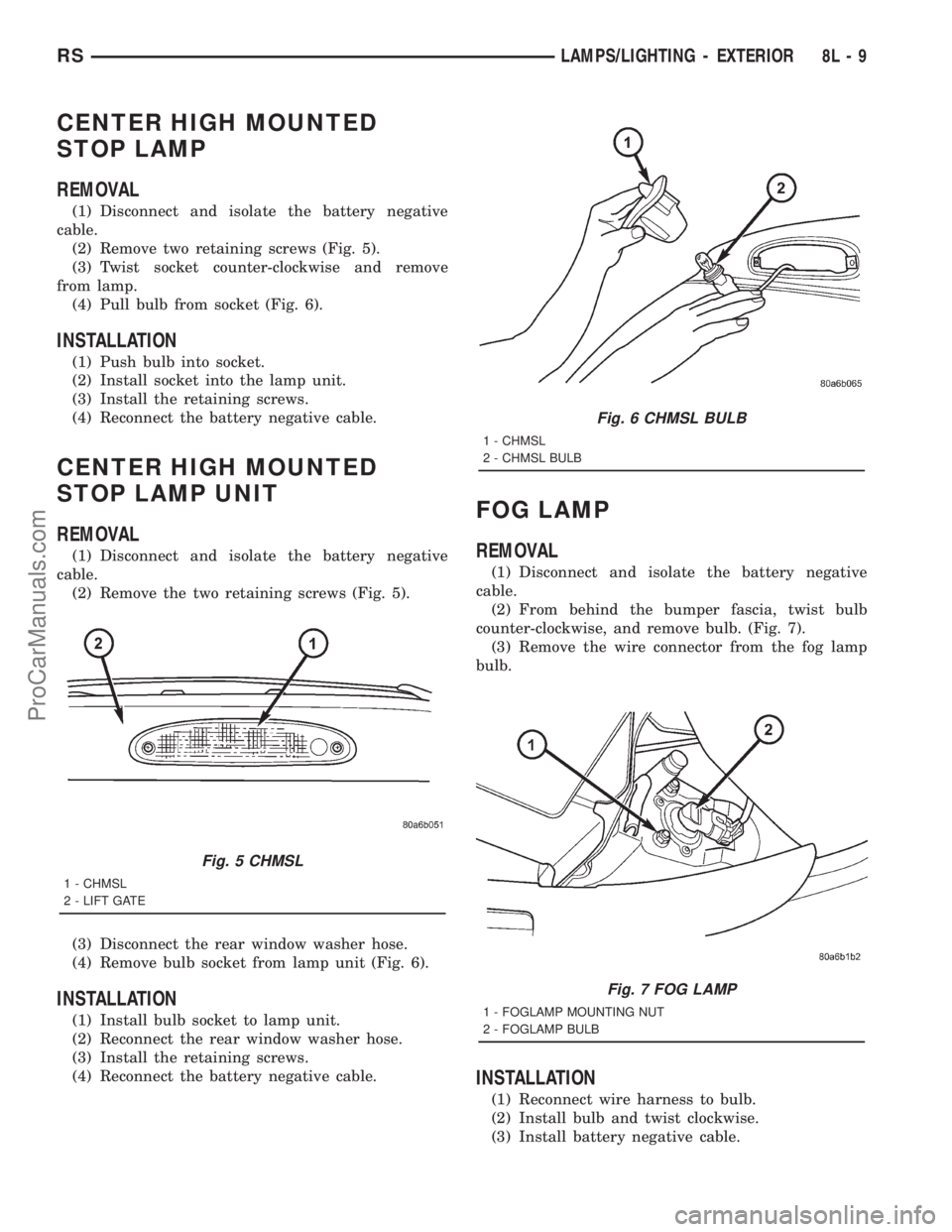
(2) Remove two retaining screws (Fig. 5).
(3) Twist socket counter-clockwise and remove
from lamp.
(4) Pull bulb from socket (Fig. 6).
INSTALLATION
(1) Push bulb into socket.
(2) Install socket into the lamp unit.
(3) Install the retaining screws.
(4) Reconnect the battery negative cable.
CENTER HIGH MOUNTED
STOP LAMP UNIT
REMOVAL
(1) Disconnect and isolate the battery negative
cable.
(2) Remove the two retaining screws (Fig. 5).
(3) Disconnect the rear window washer hose.
(4) Remove bulb socket from lamp unit (Fig. 6).
INSTALLATION
(1) Install bulb socket to lamp unit.
(2) Reconnect the rear window washer hose.
(3) Install the retaining screws.
(4) Reconnect the battery negative cable.
FOG LAMP
REMOVAL
(1) Disconnect and isolate the battery negative
cable.
(2) From behind the bumper fascia, twist bulb
counter-clockwise, and remove bulb. (Fig. 7).
(3) Remove the wire connector from the fog lamp
bulb.
INSTALLATION
(1) Reconnect wire harness to bulb.
(2) Install bulb and twist clockwise.
(3) Install battery negative cable.
Fig. 5 CHMSL
1 - CHMSL
2 - LIFT GATE
Fig. 6 CHMSL BULB
1 - CHMSL
2 - CHMSL BULB
Fig. 7 FOG LAMP
1 - FOGLAMP MOUNTING NUT
2 - FOGLAMP BULB
RSLAMPS/LIGHTING - EXTERIOR8L-9
ProCarManuals.com
Page 483 of 2321
FOG LAMP UNIT
REMOVAL
(1) Disconnect and isolate the battery negative
cable.
(2) From behind the bumper fascia, disconnect the
wire harness from the fog lamp bulb (Fig. 7).
(3) Remove mounting nuts.
INSTALLATION
(1) Install mounting nuts.
(2) Reconnect the wire harness to the fog lamp
bulb.
(3) Reconnect the battery negative cable.
ADJUSTMENT
FOG LAMP ALIGNMENT
Prepare an alignment screen. (Refer to 8 - ELEC-
TRICAL/LAMPS/LIGHTING - EXTERIOR/HEAD-
LAMP UNIT - ADJUSTMENTS). A properly aligned
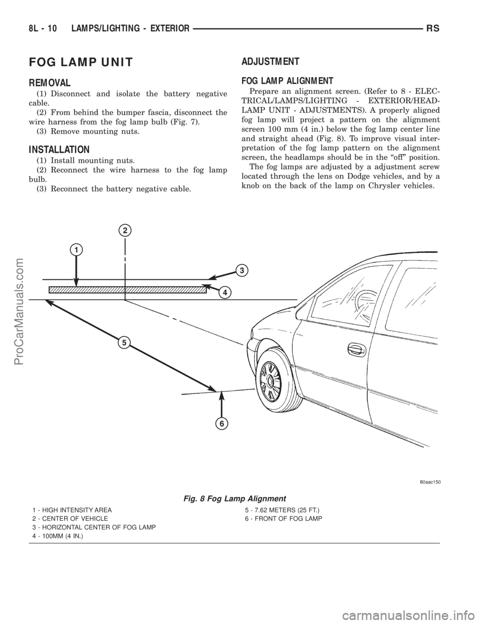
fog lamp will project a pattern on the alignment
screen 100 mm (4 in.) below the fog lamp center line
and straight ahead (Fig. 8). To improve visual inter-
pretation of the fog lamp pattern on the alignment
screen, the headlamps should be in the ªoffº position.
The fog lamps are adjusted by a adjustment screw
located through the lens on Dodge vehicles, and by a
knob on the back of the lamp on Chrysler vehicles.
Fig. 8 Fog Lamp Alignment
1 - HIGH INTENSITY AREA
2 - CENTER OF VEHICLE
3 - HORIZONTAL CENTER OF FOG LAMP
4 - 100MM (4 IN.)5 - 7.62 METERS (25 FT.)
6 - FRONT OF FOG LAMP
8L - 10 LAMPS/LIGHTING - EXTERIORRS
ProCarManuals.com
Page 484 of 2321
HEADLAMP
REMOVAL
(1)Disconnect and isolate the battery negative cable.
(2) Remove headlamp unit retaining screws.
(3) Remove headlamp unit to expose back of unit.
(4) Remove wiring connector from bulb.
(5) Rotate headlamp bulb retaining ring counter-
clockwise.
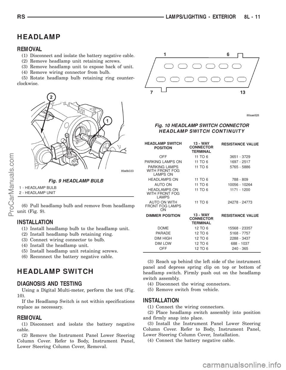
(6) Pull headlamp bulb and remove from headlamp
unit (Fig. 9).
INSTALLATION
(1) Install headlamp bulb to the headlamp unit.
(2) Install headlamp bulb retaining ring.
(3) Connect wiring connector to bulb.
(4) Install the headlamp unit.
(5) Install headlamp unit retaining screws.
(6) Reconnect the battery negative cable.
HEADLAMP SWITCH
DIAGNOSIS AND TESTING
Using a Digital Multi-meter, perform the test (Fig.
10).
If the Headlamp Switch is not within specifications
replace as necessary.
REMOVAL
(1) Disconnect and isolate the battery negative
cable.
(2) Remove the Instrument Panel Lower Steering
Column Cover. Refer to Body, Instrument Panel,
Lower Steering Column Cover, Removal.(3) Reach up behind the left side of the instrument
panel and depress spring clip on top or bottom of
headlamp switch. Firmly push out on the headlamp
switch assembly.
(4) Disconnect the wiring connectors.
(5) Remove switch from vehicle.
INSTALLATION
(1) Connect the wiring connectors.
(2) Place headlamp switch assembly into position
and firmly snap into place.
(3) Install the Instrument Panel Lower Steering
Column Cover. Refer to Body, Instrument Panel,
Lower Steering Column Cover, Installation.
(4) Connect the battery negative cable.
Fig. 9 HEADLAMP BULB
1 - HEADLAMP BULB
2 - HEADLAMP UNIT
Fig. 10 HEADLAMP SWITCH CONNECTOR
HEADLAMP SWITCH CONTINUITY
HEADLAMP SWITCH
POSITION13-WAY
CONNECTOR
TERMINALRESISTANCE VALUE
OFF 11 TO 6 3651 - 3729
PARKING LAMPS ON 11 TO 6 1697 - 2517
PARKING LAMPS
WITH FRONT FOG
LAMPS ON11 TO 6 5765 - 5886
HEADLAMPS ON 11 TO 6 788 - 809
AUTO ON 11 TO 6 10056 - 10264
HEADLAMPS ON
WITH FRONT FOG
LAMPS11 TO 6 1171 - 1200
AUTO ON WITH
FRONT FOG LAMPS
ON11 TO 6 24278 - 24773
DIMMER POSITION13-WAY
CONNECTOR
TERMINALRESISTANCE VALUE
DOME 12 TO 6 15568 - 23357
PARADE 12 TO 6 5168 - 7757
DIM HIGH 12 TO 6 2288 - 3437
DIM LOW 12 TO 6 688 - 1037
OFF 12 TO 6 240 - 365
RSLAMPS/LIGHTING - EXTERIOR8L-11
ProCarManuals.com
Page 494 of 2321
LAMPS
TABLE OF CONTENTS
page page
LAMPS/LIGHTING - EXTERIOR
SPECIFICATIONS.........................1
FOG LAMP
REMOVAL...............................1
INSTALLATION............................2
FOG LAMP UNIT
ADJUSTMENTS...........................2
FRONT POSITION LAMP
REMOVAL...............................3
INSTALLATION............................3
HEADLAMP
REMOVAL...............................3
INSTALLATION............................3
HEADLAMP LEVELING MOTOR
DIAGNOSIS AND TESTING..................4
HEADLAMP LEVELING MOTOR.............4
REMOVAL...............................4
INSTALLATION............................4
HEADLAMP LEVELING SWITCH
DESCRIPTION............................4DIAGNOSIS AND TESTING..................4
HEADLAMP LEVELING SWITCH............4
HEADLAMP SWITCH
DIAGNOSIS AND TESTING..................5
HEADLAMP SWITCH.....................5
HEADLAMP UNIT
ADJUSTMENTS...........................6
PARK/TURN SIGNAL LAMP
REMOVAL...............................7
INSTALLATION............................7
REAR FOG LAMP
DESCRIPTION............................7
REPEATER LAMP
REMOVAL...............................7
INSTALLATION............................7
TAIL LAMP
REMOVAL...............................8
INSTALLATION............................8
LAMPS/LIGHTING - EXTERIOR
SPECIFICATIONS
EXTERIOR LAMPS
BULB APPLICATION CHART
LAMP BULB TYPE
HEADLAMP H7
FRONT POSITION W5W
FRONT TURN SIGNAL PY21W
SIDE REPEATER T4W
LICENSE PLATE W5W/168
REAR TAIL AND STOP P21/5W
REAR TURN SIGNAL PY21W
BACK-UP P21W
REAR FOG P21W
CENTER HIGH
MOUNTED STOP LAMPW16W/921
For additional bulb applications refer to the domestic
Lamps section of the service manual.
FOG LAMP
REMOVAL
(1) Disconnect and isolate the battery negative
cable.
(2) Remove access cover from under bumper fascia.
(3) Disengage spring clip from fog lamp (Fig. 1).
Fig. 1 FOG LAMP
1 - SPRING CLIP
2 - FOG LAMP BULB
RGLAMPS8La-1
ProCarManuals.com
Page 495 of 2321
(4) Remove bulb from lamp.
(5) Disconnect wire harness connector.
INSTALLATION
(1) Connect wire harness connector.
(2) Install bulb to lamp.
(3) Engage spring clip to fog lamp.
(4) Install access cover under bumper fascia.
(5) Connect battery negative cable.
FOG LAMP UNIT
ADJUSTMENT
FOG LAMP ALIGNMENT
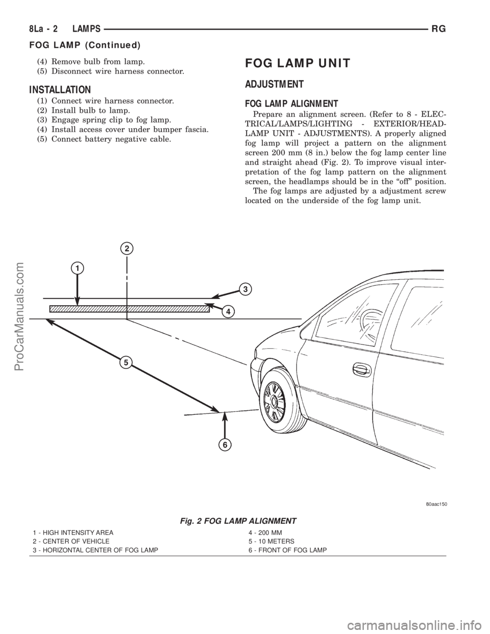
Prepare an alignment screen. (Refer to 8 - ELEC-
TRICAL/LAMPS/LIGHTING - EXTERIOR/HEAD-
LAMP UNIT - ADJUSTMENTS). A properly aligned
fog lamp will project a pattern on the alignment
screen 200 mm (8 in.) below the fog lamp center line
and straight ahead (Fig. 2). To improve visual inter-
pretation of the fog lamp pattern on the alignment
screen, the headlamps should be in the ªoffº position.
The fog lamps are adjusted by a adjustment screw
located on the underside of the fog lamp unit.
Fig. 2 FOG LAMP ALIGNMENT
1 - HIGH INTENSITY AREA
2 - CENTER OF VEHICLE
3 - HORIZONTAL CENTER OF FOG LAMP4 - 200 MM
5 - 10 METERS
6 - FRONT OF FOG LAMP
8La - 2 LAMPSRG
FOG LAMP (Continued)
ProCarManuals.com
Page 498 of 2321
- ELECTRICAL/LAMPS/LIGHTING - EXTERIOR/
HEADLAMP SWITCH - DIAGNOSIS AND TEST-
ING) for diagnosis of the headlamp leveling switch. If
the headlamp leveling switch is faulty, the headlamp
switch must be replaced.
HEADLAMP SWITCH
DIAGNOSIS AND TESTING - HEADLAMP
SWITCH
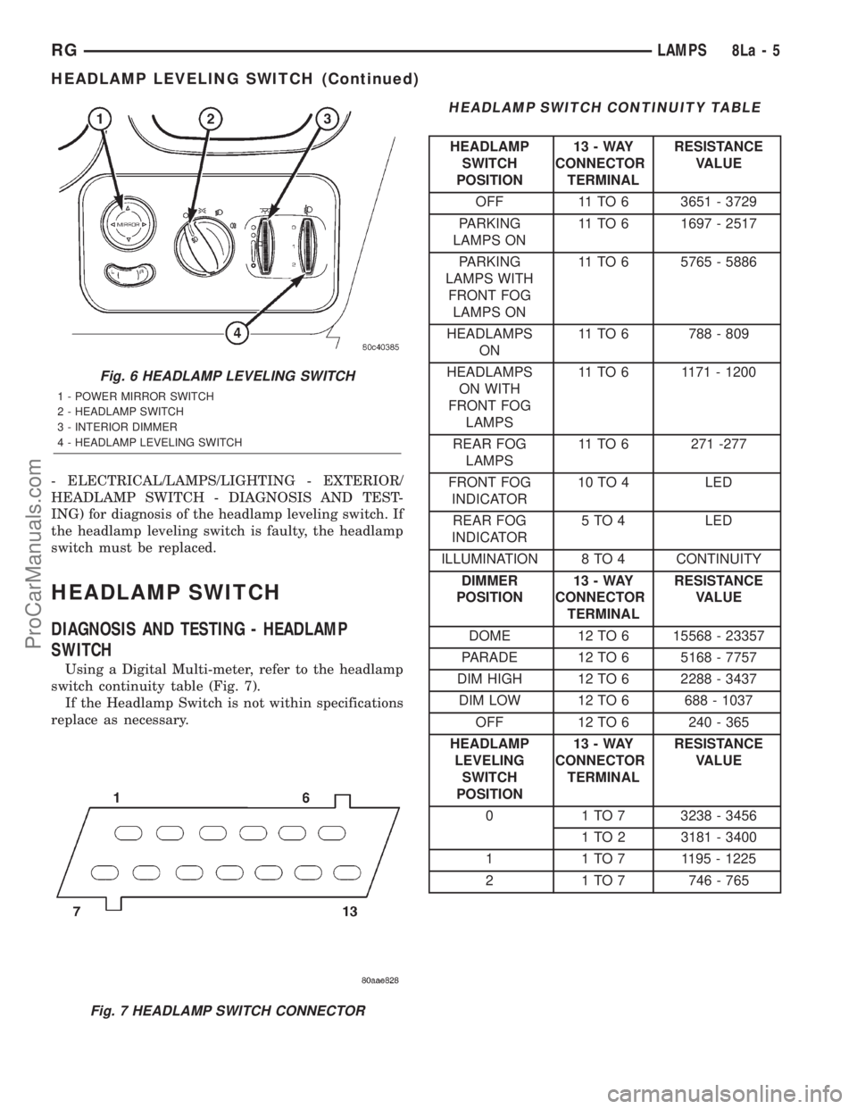
Using a Digital Multi-meter, refer to the headlamp
switch continuity table (Fig. 7).
If the Headlamp Switch is not within specifications
replace as necessary.
HEADLAMP SWITCH CONTINUITY TABLE
HEADLAMP
SWITCH
POSITION13-WAY
CONNECTOR
TERMINALRESISTANCE
VALUE
OFF 11 TO 6 3651 - 3729
PARKING
LAMPS ON11 TO 6 1697 - 2517
PARKING
LAMPS WITH
FRONT FOG
LAMPS ON11 TO 6 5765 - 5886
HEADLAMPS
ON11 TO 6 788 - 809
HEADLAMPS
ON WITH
FRONT FOG
LAMPS11 TO 6 1171 - 1200
REAR FOG
LAMPS11 TO 6 271 -277
FRONT FOG
INDICATOR10 TO 4 LED
REAR FOG
INDICATOR5 TO 4 LED
ILLUMINATION 8 TO 4 CONTINUITY
DIMMER
POSITION13-WAY
CONNECTOR
TERMINALRESISTANCE
VALUE
DOME 12 TO 6 15568 - 23357
PARADE 12 TO 6 5168 - 7757
DIM HIGH 12 TO 6 2288 - 3437
DIM LOW 12 TO 6 688 - 1037
OFF 12 TO 6 240 - 365
HEADLAMP
LEVELING
SWITCH
POSITION13-WAY
CONNECTOR
TERMINALRESISTANCE
VALUE
0 1 TO 7 3238 - 3456
1 TO 2 3181 - 3400
1 1 TO 7 1195 - 1225
2 1 TO 7 746 - 765
Fig. 6 HEADLAMP LEVELING SWITCH
1 - POWER MIRROR SWITCH
2 - HEADLAMP SWITCH
3 - INTERIOR DIMMER
4 - HEADLAMP LEVELING SWITCH
Fig. 7 HEADLAMP SWITCH CONNECTOR
RGLAMPS8La-5
HEADLAMP LEVELING SWITCH (Continued)
ProCarManuals.com
Page 500 of 2321
PARK/TURN SIGNAL LAMP
REMOVAL
(1) Disconnect and isolate the battery negative
cable.
(2) Remove the headlamp unit.
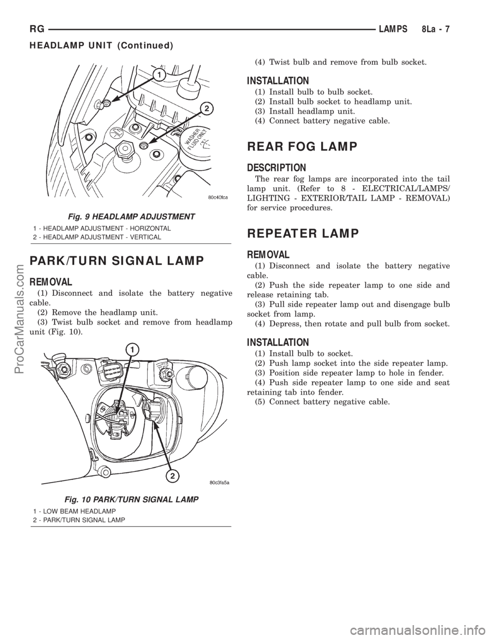
(3) Twist bulb socket and remove from headlamp
unit (Fig. 10).(4) Twist bulb and remove from bulb socket.
INSTALLATION
(1) Install bulb to bulb socket.
(2) Install bulb socket to headlamp unit.
(3) Install headlamp unit.
(4) Connect battery negative cable.
REAR FOG LAMP
DESCRIPTION
The rear fog lamps are incorporated into the tail
lamp unit. (Refer to 8 - ELECTRICAL/LAMPS/
LIGHTING - EXTERIOR/TAIL LAMP - REMOVAL)
for service procedures.
REPEATER LAMP
REMOVAL
(1) Disconnect and isolate the battery negative
cable.
(2) Push the side repeater lamp to one side and
release retaining tab.
(3) Pull side repeater lamp out and disengage bulb
socket from lamp.
(4) Depress, then rotate and pull bulb from socket.
INSTALLATION
(1) Install bulb to socket.
(2) Push lamp socket into the side repeater lamp.
(3) Position side repeater lamp to hole in fender.
(4) Push side repeater lamp to one side and seat
retaining tab into fender.
(5) Connect battery negative cable.
Fig. 9 HEADLAMP ADJUSTMENT
1 - HEADLAMP ADJUSTMENT - HORIZONTAL
2 - HEADLAMP ADJUSTMENT - VERTICAL
Fig. 10 PARK/TURN SIGNAL LAMP
1 - LOW BEAM HEADLAMP
2 - PARK/TURN SIGNAL LAMP
RGLAMPS8La-7
HEADLAMP UNIT (Continued)
ProCarManuals.com
Page 501 of 2321
TAIL LAMP
REMOVAL
(1) Disconnect and isolate the battery negative
cable.
(2) Remove the tail lamp unit (Refer to 8 - ELEC-
TRICAL/LAMPS/LIGHTING - EXTERIOR/TAIL
LAMP UNIT - REMOVAL).
(3) Squeeze the tabs on housing retaining the
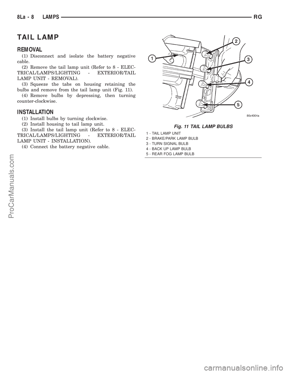
bulbs and remove from the tail lamp unit (Fig. 11).
(4) Remove bulbs by depressing, then turning
counter-clockwise.
INSTALLATION
(1) Install bulbs by turning clockwise.
(2) Install housing to tail lamp unit.
(3) Install the tail lamp unit (Refer to 8 - ELEC-
TRICAL/LAMPS/LIGHTING - EXTERIOR/TAIL
LAMP UNIT - INSTALLATION).
(4) Connect the battery negative cable.
Fig. 11 TAIL LAMP BULBS
1 - TAIL LAMP UNIT
2 - BRAKE/PARK LAMP BULB
3 - TURN SIGNAL BULB
4 - BACK UP LAMP BULB
5 - REAR FOG LAMP BULB
8La - 8 LAMPSRG
ProCarManuals.com
Page 618 of 2321
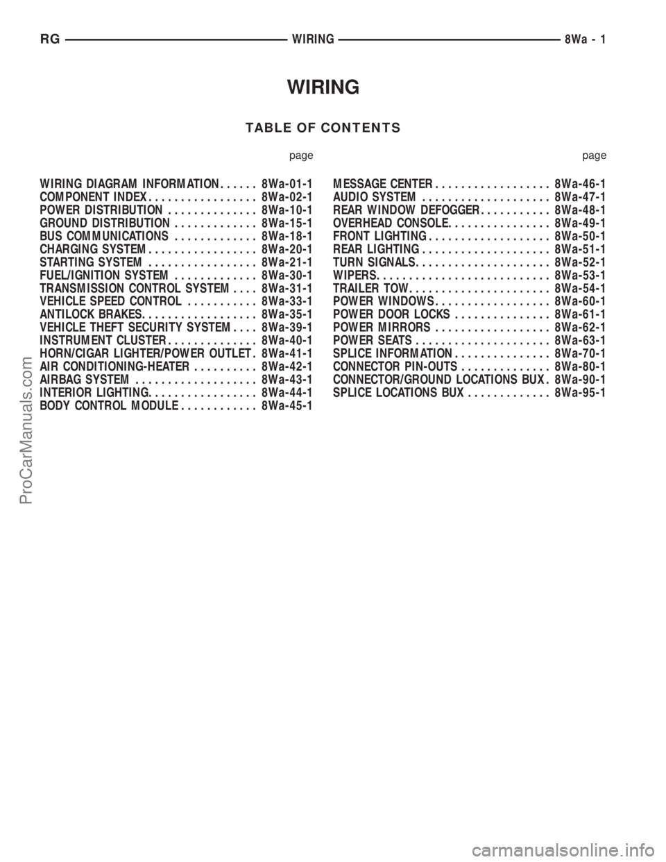
WIRING
TABLE OF CONTENTS
page page
WIRING DIAGRAM INFORMATION...... 8Wa-01-1
COMPONENT INDEX................. 8Wa-02-1
POWER DISTRIBUTION.............. 8Wa-10-1
GROUND DISTRIBUTION............. 8Wa-15-1
BUS COMMUNICATIONS............. 8Wa-18-1
CHARGING SYSTEM................. 8Wa-20-1
STARTING SYSTEM................. 8Wa-21-1
FUEL/IGNITION SYSTEM............. 8Wa-30-1
TRANSMISSION CONTROL SYSTEM.... 8Wa-31-1
VEHICLE SPEED CONTROL........... 8Wa-33-1
ANTILOCK BRAKES.................. 8Wa-35-1
VEHICLE THEFT SECURITY SYSTEM.... 8Wa-39-1
INSTRUMENT CLUSTER.............. 8Wa-40-1
HORN/CIGAR LIGHTER/POWER OUTLET . 8Wa-41-1
AIR CONDITIONING-HEATER.......... 8Wa-42-1
AIRBAG SYSTEM................... 8Wa-43-1
INTERIOR LIGHTING................. 8Wa-44-1
BODY CONTROL MODULE............ 8Wa-45-1MESSAGE CENTER.................. 8Wa-46-1
AUDIO SYSTEM.................... 8Wa-47-1
REAR WINDOW DEFOGGER........... 8Wa-48-1
OVERHEAD CONSOLE................ 8Wa-49-1
FRONT LIGHTING................... 8Wa-50-1
REAR LIGHTING.................... 8Wa-51-1
TURN SIGNALS..................... 8Wa-52-1
WIPERS........................... 8Wa-53-1
TRAILER TOW...................... 8Wa-54-1
POWER WINDOWS.................. 8Wa-60-1
POWER DOOR LOCKS............... 8Wa-61-1
POWER MIRRORS.................. 8Wa-62-1
POWER SEATS..................... 8Wa-63-1
SPLICE INFORMATION............... 8Wa-70-1
CONNECTOR PIN-OUTS.............. 8Wa-80-1
CONNECTOR/GROUND LOCATIONS BUX . 8Wa-90-1
SPLICE LOCATIONS BUX............. 8Wa-95-1 RGWIRING
8Wa-1
ProCarManuals.com
Page 632 of 2321
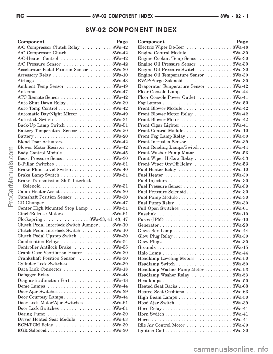
8W-02 COMPONENT INDEX
Component Page
A/C Compressor Clutch Relay........... 8Wa-42
A/C Compressor Clutch................ 8Wa-42
A/C-Heater Control................... 8Wa-42
A/C Pressure Sensor.................. 8Wa-42
Accelerator Pedal Position Sensor........ 8Wa-30
Accessory Relay...................... 8Wa-10
Airbags............................. 8Wa-43
Ambient Temp Sensor................. 8Wa-49
Antenna............................ 8Wa-47
ATC Remote Sensor................... 8Wa-42
Auto Shut Down Relay................. 8Wa-30
Auto Temp Control.................... 8Wa-42
Automatic Day/Night Mirror............ 8Wa-49
Autostick Switch..................... 8Wa-31
Back-Up Lamp Switch................. 8Wa-51
Battery Temperature Sensor............ 8Wa-20
Battery............................. 8Wa-20
Blend Door Actuators.................. 8Wa-42
Blower Motor Resistor................. 8Wa-42
Body Control Module.................. 8Wa-45
Boost Pressure Sensor................. 8Wa-30
B-Pillar Switches..................... 8Wa-61
Brake Fluid Level Switch............... 8Wa-40
Brake Lamp Switch................... 8Wa-51
Brake Transmission Shift Interlock
Solenoid.......................... 8Wa-31
Cabin Heater Assist................... 8Wa-30
Camshaft Position Sensor.............. 8Wa-30
CD Changer......................... 8Wa-47
Center High Mounted Stop Lamp........ 8Wa-51
Cinch/Release Motors.................. 8Wa-61
Clockspring................. 8Wa-33, 41, 43, 47
Clutch Pedal Interlock Switch Jumper..... 8Wa-10
Clutch Pedal Interlock Switch........... 8Wa-10
Clutch Pedal Upstop Switch............. 8Wa-30
Combination Relays................... 8Wa-54
Controller Antilock Brake.............. 8Wa-35
Crank Case Ventilation Heater.......... 8Wa-30
Crankshaft Position Sensor............. 8Wa-30
Cylinder Lock Switches................ 8Wa-39
Data Link Connector.................. 8Wa-18
Defogger Relay....................... 8Wa-48
Diagnostic Junction Port............... 8Wa-18
Dome Lamps........................ 8Wa-44
Door Ajar Switches.................... 8Wa-39
Door Courtesy Lamps.................. 8Wa-44
Door Lock Motor/Ajar Switches.......... 8Wa-61
Door Lock Switches................... 8Wa-61
Dosing Pump........................ 8Wa-30
Driver Heated Seat Module............. 8Wa-63
ECM/PCM Relay..................... 8Wa-30
EGR Solenoid........................ 8Wa-30Component Page
Electric Wiper De-Icer................. 8Wa-48
Engine Control Module................ 8Wa-30
Engine Coolant Temp Sensor............ 8Wa-30
Engine Oil Pressure Sensor............. 8Wa-30
Engine Oil Pressure Switch............. 8Wa-30
Engine Oil Temperature Sensor.......... 8Wa-30
EVAP/Purge Solenoid.................. 8Wa-30
Evaporator Temperature Sensor......... 8Wa-42
Floor Console Lamp................... 8Wa-44
Floor Console Power Outlet............. 8Wa-41
Fog Lamps.......................... 8Wa-50
Front Blower Module.................. 8Wa-42
Front Blower Motor Relay.............. 8Wa-42
Front Blower Motor................... 8Wa-42
Front Cigar Lighter................... 8Wa-41
Front Control Module.................. 8Wa-10
Front Fog Lamp Relay................. 8Wa-50
Front Intrusion Sensor................. 8Wa-39
Front Reading Lamps/Switch............ 8Wa-44
Front Washer Pump Motor.............. 8Wa-53
Front Wiper Hi/Low Relay.............. 8Wa-53
Front Wiper On/Off Relay.............. 8Wa-53
Fuel Heater Relay.................... 8Wa-10
Fuel Heater......................... 8Wa-30
Fuel Injectors........................ 8Wa-30
Fuel Pressure Sensor.................. 8Wa-30
Fuel Pressure Solenoid................. 8Wa-30
Fuel Pump Module.................... 8Wa-30
Fuel Pump Relay..................... 8Wa-30
Full Open Switches................... 8Wa-61
Fuselink............................ 8Wa-10
Fuses (IPM)......................... 8Wa-10
Generator........................... 8Wa-20
Glove Box Lamp...................... 8Wa-44
Glow Plug Relay...................... 8Wa-30
Glow Plugs.......................... 8Wa-30
Grounds............................ 8Wa-15
Halo Lamp.......................... 8Wa-44
Headlamp Leveling Motors............. 8Wa-50
Headlamp Switch..................... 8Wa-50
Headlamp Washer Pump Motor.......... 8Wa-53
Headlamp Washer Relay............... 8Wa-53
Headlamps.......................... 8Wa-50
Heated Seat Backs.................... 8Wa-63
Heated Seat Cushions................. 8Wa-63
High Beam Lamps.................... 8Wa-50
Hood Ajar Switch..................... 8Wa-39
Horn Relay.......................... 8Wa-41
Horn Switch......................... 8Wa-41
Horns.............................. 8Wa-41
Idle Air Control Motor................. 8Wa-30
Ignition Coil......................... 8Wa-30
RG8W-02 COMPONENT INDEX8Wa-02-1
ProCarManuals.com