DODGE TOWN AND COUNTRY 2001 Service Manual
Manufacturer: DODGE, Model Year: 2001, Model line: TOWN AND COUNTRY, Model: DODGE TOWN AND COUNTRY 2001Pages: 2321, PDF Size: 68.09 MB
Page 551 of 2321
INSTALLATION
(1) Position the flex drive assembly in the vehicle.
(2) Install the flex drive on the lower drive unit.
Push straight on until it snaps in place. It may be
necessary to rotate drive unit gear slightly until the
flex drive seats in place.
(3) Install the lower drive unit cover and retaining
screws.
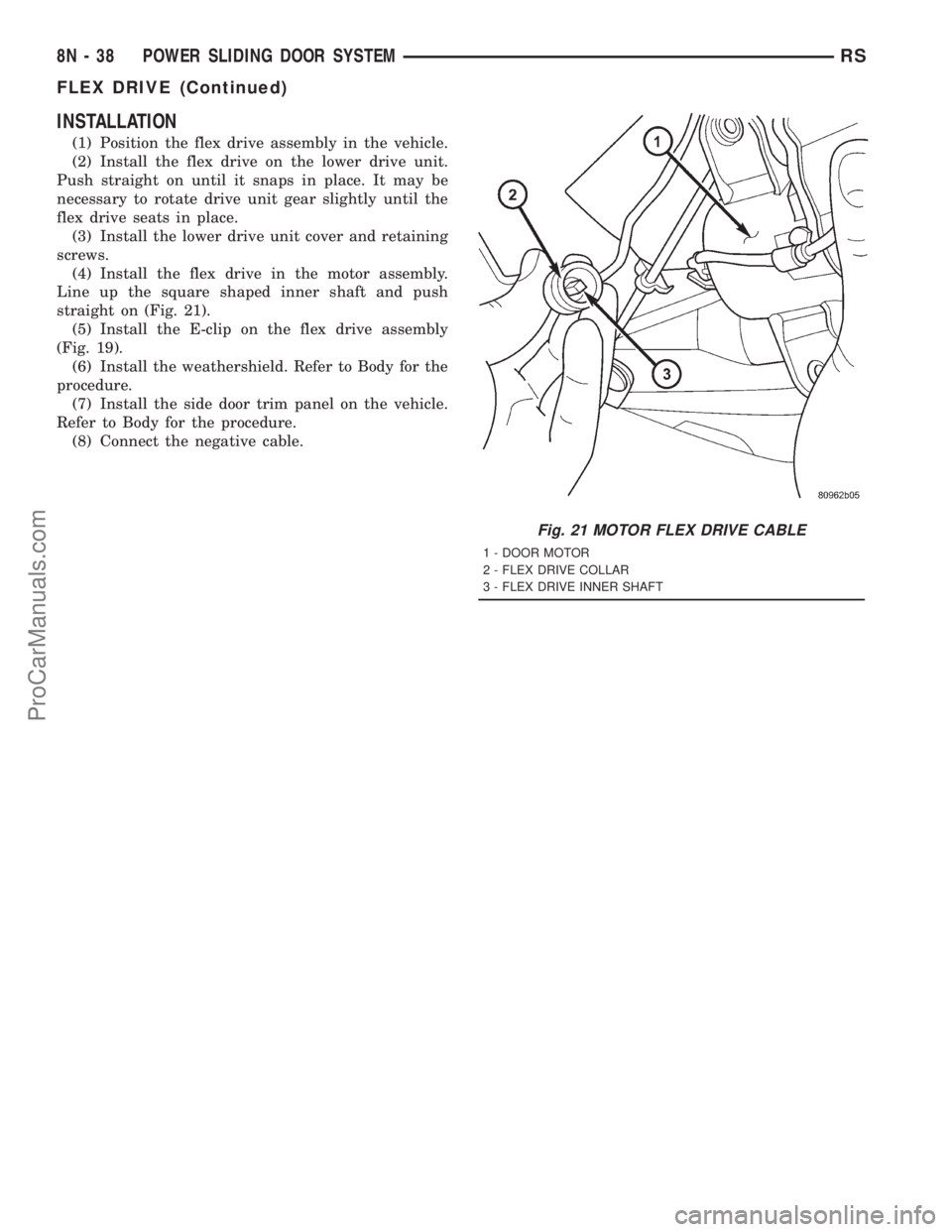
(4) Install the flex drive in the motor assembly.
Line up the square shaped inner shaft and push
straight on (Fig. 21).
(5) Install the E-clip on the flex drive assembly
(Fig. 19).
(6) Install the weathershield. Refer to Body for the
procedure.
(7) Install the side door trim panel on the vehicle.
Refer to Body for the procedure.
(8) Connect the negative cable.
Fig. 21 MOTOR FLEX DRIVE CABLE
1 - DOOR MOTOR
2 - FLEX DRIVE COLLAR
3 - FLEX DRIVE INNER SHAFT
8N - 38 POWER SLIDING DOOR SYSTEMRS
FLEX DRIVE (Continued)
ProCarManuals.com
Page 552 of 2321
POWER LOCKS
TABLE OF CONTENTS
page page
POWER LOCKS
DESCRIPTION...........................39
OPERATION.............................40
DOOR LOCK MOTOR
DIAGNOSIS AND TESTING.................41
DOOR LOCK MOTOR....................41
DOOR LOCK SWITCH
DESCRIPTION...........................41
DIAGNOSIS AND TESTING.................41
DOOR LOCK SWITCH...................41
REMOVAL..............................42
INSTALLATION...........................42
KEYLESS ENTRY TRANSMITTER
STANDARD PROCEDURE..................42
HORN CHIRP PREFERENCE..............42BATTERY REPLACEMENT................42
SPECIFICATIONS........................42
REMOTE KEYLESS ENTRY MODULE
DESCRIPTION...........................43
OPERATION.............................43
DIAGNOSIS AND TESTING.................43
REMOTE KEYLESS ENTRY...............43
STANDARD PROCEDURE..................43
PROGRAMMING RKE MODULE............43
REMOVAL..............................43
INSTALLATION...........................44
SLIDING DOOR LOCK MOTOR
REMOVAL..............................44
INSTALLATION...........................44
POWER LOCKS
DESCRIPTION
POWER DOOR LOCK SYSTEM
The front doors, sliding door(s) and liftgate are
equipped with actuator motors to lock or unlock the
latch mechanisms. The door lock actuator motor is
not serviced separately from the door latch, except
for the sliding door(s).
AUTOMATIC DOOR LOCKS
The vehicle comes with two options for power door
locks:
²Rolling automatic lock (ENABLE), doors auto-
matically lock at approximately at 25.7 Km/h (16
mph).
²No rolling automatic lock (DISABLE), doors do
not automatically lock when the vehicle is moving.
DOOR LOCK INHIBIT
The BCM cancels out the door lock switch actua-
tion, when the key is in the Ignition Switch and
either front door is open.
Pressing the key fob RKE lock/unlock under these
conditions results in normal lock/unlock activation.
CENTRAL LOCKING
If equipped with Vehicle Theft Security System
(VTSS), all the doors can be locked with the key by
using any of the door lock cylinders. Turning the key
to the lock position will lock all the doors. If a sliding
door is open when this is done, the sliding door will
lock when it is closed.
DOOR LOCK CIRCUIT PROTECTION
The door lock system is protected by a 40 amp fuse
located in the IPM. The BCM receives lock/unlock
input and will turn on the appropriate drivers and
provide a voltage level to the door lock motor for a
specific time. The IPM is located along the side of the
vehicle battery in the engine compartment.
RSPOWER LOCKS8N-39
ProCarManuals.com
Page 553 of 2321
REMOTE KEYLESS ENTRY SYSTEM
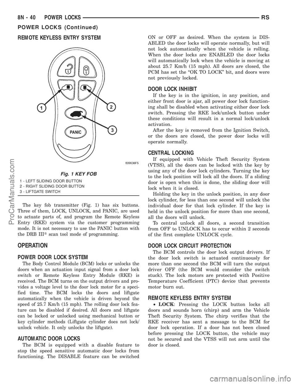
The key fob transmitter (Fig. 1) has six buttons.
Three of them, LOCK, UNLOCK, and PANIC, are used
to actuate parts of, and program the Remote Keyless
Entry (RKE) system via the customer programming
mode. It is not necessary to use the PANIC button with
the DRB IIItscan tool mode of programming.
OPERATION
POWER DOOR LOCK SYSTEM
The Body Control Module (BCM) locks or unlocks the
doors when an actuation input signal from a door lock
switch or Remote Keyless Entry Module (RKE) is
received. The BCM turns on the output drivers and pro-
vides a voltage level to the door lock motor for a speci-
fied time. The BCM locks the doors and liftgate
automatically when the vehicle is driven beyond the
speed of 25.7 Km/h (15 mph). The rolling door lock fea-
ture can be disabled if desired. All doors and liftgate
can be locked or unlocked using mechanical button or
key cylinder methods (Liftgate cylinder does not lock/
unlock vehicle. It only unlocks the liftgate).
AUTOMATIC DOOR LOCKS
The BCM is equipped with a disable feature to
stop the speed sensitive automatic door locks from
functioning. The DISABLE feature can be switchedON or OFF as desired. When the system is DIS-
ABLED the door locks will operate normally, but will
not lock automatically when the vehicle is rolling.
When the door locks are ENABLED the door locks
will automatically lock when the vehicle is moving at
about 25.7 Km/h (15 mph). All doors are closed, the
PCM has set the ªOK TO LOCKº bit, and doors were
not previously locked.
DOOR LOCK INHIBIT
If the key is in the ignition, in any position, and
either front door is ajar, all power door lock function-
ing shall be disabled when activating either door lock
switch. Pressing the RKE lock/unlock button under
these conditions will result in a normal lock/unlock
activation.
After the key is removed from the Ignition Switch,
or the doors are closed, the power door locks will
operate normally.
CENTRAL LOCKING
If equipped with Vehicle Theft Security System
(VTSS), all the doors can be locked with the key by
using any of the door lock cylinders. Turning the key
to the lock position will lock all the doors. If a sliding
door is open when this is done, the sliding door will
lock when it is closed.
Holding the key in the unlock position, in any door
lock cylinder, for less than one second will unlock the
individual door for that lock cylinder. If the key is
held in the unlock position for more than one second,
all the doors will unlock.
To central unlock all doors, a second transition
from OFF to UNLOCK has to occur within 2 seconds
of the first complete UNLOCK cycle.
DOOR LOCK CIRCUIT PROTECTION
The BCM controls the door lock output drivers. If
the door lock switch is actuated continuously for
more than one second the BCM will turn the output
driver OFF (the BCM would consider the switch
stuck). The lock motors are protected with Positive
Temperature Coefficient (PTC) device that prevents
motor burn out.
REMOTE KEYLESS ENTRY SYSTEM
²LOCK: Pressing the LOCK button locks all
doors and sounds horn (chirp) and arm the Vehicle
Theft Security System. The chirp verifies that the
RKE receiver has sent a message to the BCM for
door lock operation. If a door has not been closed
before pressing the LOCK button, the vehicle may
not be secured and the VTSS will not arm until the
door is closed.
Fig. 1 KEY FOB
1 - LEFT SLIDING DOOR BUTTON
2 - RIGHT SLIDING DOOR BUTTON
3 - LIFTGATE SWITCH
8N - 40 POWER LOCKSRS
POWER LOCKS (Continued)
ProCarManuals.com
Page 554 of 2321
²UNLOCK: Pressing the UNLOCK button once
will unlock the driver's side doors and activate the
illuminated entry system and disarm Vehicle Theft
Security System, if equipped. Pressing the UNLOCK
button twice within five seconds will unlock all doors
and activate the illuminated entry system.
²LEFT SLIDING DOOR: Pressing the LEFT
SLIDING DOOR BUTTON opens/closes the left
power sliding door remotely.
²RIGHT SLIDING DOOR: Pressing the RIGHT
SLIDING DOOR BUTTON opens/closes the right
power sliding door remotely.
²LIFTGATE: Pressing the LIFTGATE BUTTON
opens/closes the liftgate remotely.
²PANIC: Pressing the PANIC button sounds the
horns at half second intervals, flashes the exterior
lamps, and turns ON the interior lamps. The panic
alarm will remain on for three minutes, or until the
PANIC button is actuated again or the ignition
switch is turned to the RUN position.
The Remote Keyless Entry Module is capable of
retaining the transmitter Vehicle Access Code(s)
(VAC) in its memory even after vehicle power has
been interrupted.
NOTE: Additional features available to the customer
are described in the Vehicle Owners Manual.
The RKE system activates the optional memory
seat and mirror system, if equipped. Two primary
key fob transmitters can be programmed to actuate
memory seat and mirror setting 1 or 2. Two addi-
tional key fob transmitters can be added, but they
will not be able to operate the memory seat and mir-
ror system (Refer to 8 - ELECTRICAL/POWER
SEATS - OPERATION) and (Refer to 8 - ELECTRI-
CAL/POWER MIRRORS - OPERATION).
DOOR LOCK MOTOR
DIAGNOSIS AND TESTING - DOOR LOCK
MOTOR
Verify battery condition before testing door lock
motor(s) (Refer to 8 - ELECTRICAL/BATTERY SYS-
TEM/BATTERY - DIAGNOSIS AND TESTING).
To determine which motor is faulty, check each
individual door for electrical lock and unlock or dis-
connect the motor connectors one at a time, while
operating the door lock switch. In the event that
none of the motors work, the problem may be caused
by a shorted motor or a bad switch. Disconnecting
the defective motor will allow the others to work.
To test an individual door lock motor, disconnect
the electrical connector from the motor. To lock the
door, connect a 12 volt power source to the positivepin of the lock motor and a ground wire to the other
pin. Refer to the appropriate wiring information. The
wiring information includes wiring diagrams, proper
wire and connector repair procedures, further details
on wire harness routing and retention, as well as
pin-out and location views for the various wire har-
ness connectors, splices and grounds. To unlock the
door reverse the wire connections at the motor pin
terminals. If these results are NOT obtained, replace
the motor.
DOOR LOCK SWITCH
DESCRIPTION
The Power Door Lock Switch is attached to the
door trim panel with two screws.
DIAGNOSIS AND TESTING - DOOR LOCK
SWITCH
(1) Remove door trim panel. Refer to Body, Door -
Front, Trim Panel, Removal and Installation.
(2) Disconnect wire connector from back of door
lock switch.
(3) Depress switch to LOCK position.
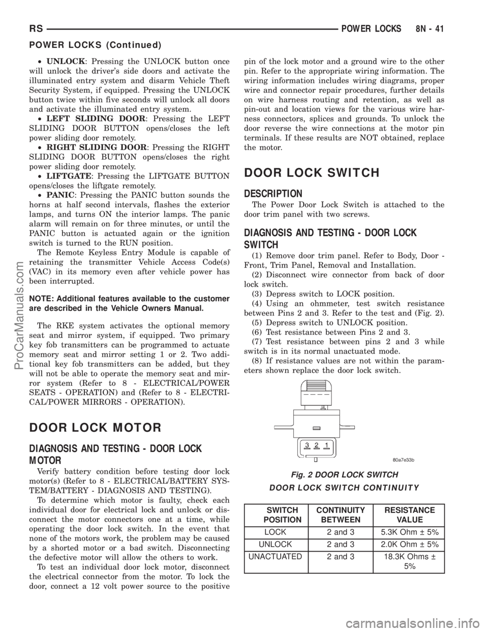
(4) Using an ohmmeter, test switch resistance
between Pins 2 and 3. Refer to the test and (Fig. 2).
(5) Depress switch to UNLOCK position.
(6) Test resistance between Pins 2 and 3.
(7) Test resistance between pins 2 and 3 while
switch is in its normal unactuated mode.
(8) If resistance values are not within the param-
eters shown replace the door lock switch.
DOOR LOCK SWITCH CONTINUITY
SWITCH
POSITIONCONTINUITY
BETWEENRESISTANCE
VALUE
LOCK 2 and 3 5.3K Ohm 5%
UNLOCK 2 and 3 2.0K Ohm 5%
UNACTUATED 2 and 3 18.3K Ohms
5%
Fig. 2 DOOR LOCK SWITCH
RSPOWER LOCKS8N-41
POWER LOCKS (Continued)
ProCarManuals.com
Page 555 of 2321
REMOVAL
(1) Disconnect and isolate the battery negative
cable.
(2) Remove door trim panel. Refer to Body, Door -
Front, Trim Panel, Removal.
(3) Disconnect wire connector from back of door
lock switch.
(4) Remove two screws to door lock switch.
(5) Remove switch from vehicle.
INSTALLATION
(1) Install the switch into the vehicle.
(2) Install the two screws to door lock switch.
(3) Connect wire connector to back of door lock
switch.
(4) Install door trim panel. Refer to Body, Door -
Front, Trim Panel, Installation.
(5) Connect the battery negative cable.
KEYLESS ENTRY
TRANSMITTER
STANDARD PROCEDURE - HORN CHIRP
PREFERENCE
DISABLING
The horn chirp can be toggled using a DRB IIItor
by using the Remote Keyless Entry (RKE) transmit-
ter.
To DISABLE (cancelling) the horn chirp feature,
press and hold the transmitter LOCK button for a
minimum of four seconds. While pressing the LOCK
button in, press the UNLOCK button. The horn chirp
feature will not function until the above procedure is
repeated.
ENABLING
The horn chirp can be toggled using a DRB IIItor
by using the Remote Keyless Entry (RKE) transmit-
ter.
To ENABLE (reinstate) the horn chirp feature, use
any one of the four key fob transmitters and reverse
the above procedures. It will ENABLE the horn chirp
feature for all transmitters.
STANDARD PROCEDURE - BATTERY
REPLACEMENT
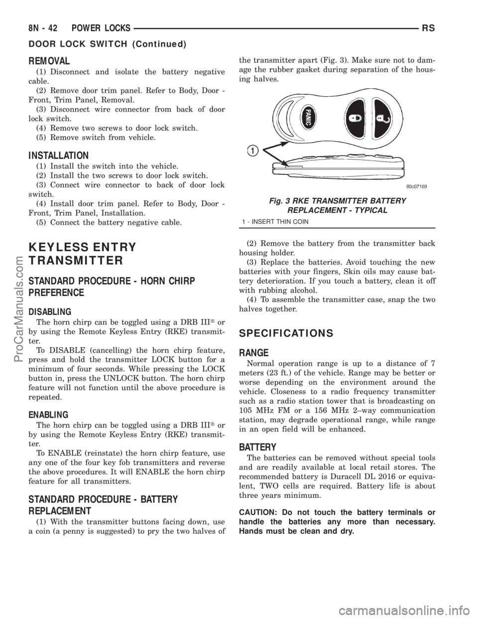
(1) With the transmitter buttons facing down, use
a coin (a penny is suggested) to pry the two halves ofthe transmitter apart (Fig. 3). Make sure not to dam-
age the rubber gasket during separation of the hous-
ing halves.
(2) Remove the battery from the transmitter back
housing holder.
(3) Replace the batteries. Avoid touching the new
batteries with your fingers, Skin oils may cause bat-
tery deterioration. If you touch a battery, clean it off
with rubbing alcohol.
(4) To assemble the transmitter case, snap the two
halves together.
SPECIFICATIONS
RANGE
Normal operation range is up to a distance of 7
meters (23 ft.) of the vehicle. Range may be better or
worse depending on the environment around the
vehicle. Closeness to a radio frequency transmitter
such as a radio station tower that is broadcasting on
105 MHz FM or a 156 MHz 2±way communication
station, may degrade operational range, while range
in an open field will be enhanced.
BATTERY
The batteries can be removed without special tools
and are readily available at local retail stores. The
recommended battery is Duracell DL 2016 or equiva-
lent, TWO cells are required. Battery life is about
three years minimum.
CAUTION: Do not touch the battery terminals or
handle the batteries any more than necessary.
Hands must be clean and dry.
Fig. 3 RKE TRANSMITTER BATTERY
REPLACEMENT - TYPICAL
1 - INSERT THIN COIN
8N - 42 POWER LOCKSRS
DOOR LOCK SWITCH (Continued)
ProCarManuals.com
Page 556 of 2321
REMOTE KEYLESS ENTRY
MODULE
DESCRIPTION
The RKE module is capable of retaining up to four
different Vehicle Access Codes.
OPERATION
Whenever the vehicle battery power is interrupted
the RKE Module will retain all vehicle access codes
in its memory. When replacing or adding a key fob
transmitter (maximum 4) a DRB IIItscan tool is
required to program the RKE Module to accept the
new Vehicle Access Code if a customer owned trans-
mitter is not available. Refer to Electrical, Remote
Keyless Entry Module, Standard Procedure - Pro-
gramming RKE Module or the Proper Body Diagnos-
tic Procedures manual.
DIAGNOSIS AND TESTING - REMOTE KEYLESS
ENTRY
Refer to the appropriate wiring information. The
wiring information includes wiring diagrams, proper
wire and connector repair procedures, further details
on wire harness routing and retention, as well as
pin-out and location views for the various wire har-
ness connectors, splices and grounds. Refer to the
proper Body Diagnostic Procedures Manual for test-
ing the Remote Keyless Entry system using a DRB
IIItscan tool. Also refer to other interrelated sys-
tems groups within this manual:
²Vehicle Theft Security System
²Power Seats
²Power Mirrors
STANDARD PROCEDURE - PROGRAMMING
RKE MODULE
(1) Using a functional key fob transmitter, unlock
the vehicle and disarm the Vehicle Theft Security
System.
(2) Insert ignition key into the ignition switch.
(3) Turn the ignition switch to RUN position with-
out starting engine.
(4) Using a functional key fob transmitter, press
and hold the UNLOCK button for a minimum five
seconds (maximum ten seconds).
(5) While still holding UNLOCK button, and
before ten seconds passes, press the PANIC button
and release both at the same time. A single chime
will sound to verify that the RKE module is set to
receive the new Vehicle Access Code(s).
(6) Within 30 seconds of the chime, press and
release the ªLOCKº and ªUNLOCKº buttons on the
transmitter at the same time. Then press any one of
the buttons. The BCM will sound an abbreviatedchime to acknowledge that the programming of the
transmitter has been completed and was successful.
(7) Repeat step 6 for all transmitters that will be
used with this vehicle (up to 4 total).
(8) Programming mode will last for 30 seconds. To
get out of programming mode sooner, turn the igni-
tion OFF. A single chime will sound to verify that the
RKE module will no longer accept additional Vehicle
Access Code(s).
(9) When Vehicle Access Code(s) programming is
complete, turn the ignition switch to the OFF posi-
tion and verify RKE system operation using each key
fob.
NOTE:
Only the two key fob transmitters that have been
programmed to the memory seat and mirror system
will operate it. If any key fob is replaced, the mem-
ory seat and mirror module will require program-
ming. (Refer to 8 - ELECTRICAL/POWER SEATS -
DIAGNOSIS AND TESTING).
REMOVAL
(1) Disconnect and isolate the battery negative
cable.
(2) Remove instrument panel top cover (Refer to
23 - BODY/INSTRUMENT PANEL/INSTRUMENT
PANEL TOP PAD - REMOVAL).
(3) Remove screws holding RKE module to instru-
ment panel.
(4) Disconnect wire connector from RKE module
(Fig. 4).
(5) Remove the RKE module from vehicle.
Fig. 4 RKE MODULE
1 - REMOTE KEYLESS ENTRY MODULE
2 - INSTRUMENT PANEL
3 - DEMISTER DUCT
RSPOWER LOCKS8N-43
ProCarManuals.com
Page 557 of 2321
INSTALLATION
(1) Position the RKE module and install the
screws.
(2) Connect the wire connector to the RKE module
(Fig. 4).
(3) Install the instrument panel top pad.
(4) Connect the battery negative cable.
SLIDING DOOR LOCK MOTOR
REMOVAL
(1) Disconnect and isolate the negative battery
cable.
(2) Remove sliding door trim panel (Refer to 23 -
BODY/DOORS - SLIDING/TRIM PANEL - REMOV-
AL).
(3) Remove sound pad as necessary.
(4) Remove latch/lock control cover.
(5) Remove latch/lock control.
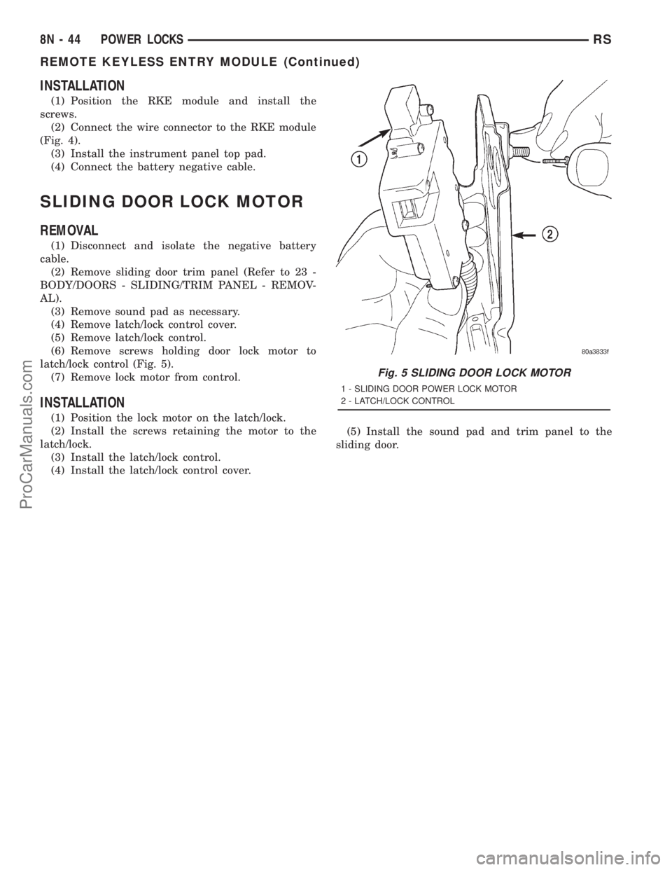
(6) Remove screws holding door lock motor to
latch/lock control (Fig. 5).
(7) Remove lock motor from control.
INSTALLATION
(1) Position the lock motor on the latch/lock.
(2) Install the screws retaining the motor to the
latch/lock.
(3) Install the latch/lock control.
(4) Install the latch/lock control cover.(5) Install the sound pad and trim panel to the
sliding door.
Fig. 5 SLIDING DOOR LOCK MOTOR
1 - SLIDING DOOR POWER LOCK MOTOR
2 - LATCH/LOCK CONTROL
8N - 44 POWER LOCKSRS
REMOTE KEYLESS ENTRY MODULE (Continued)
ProCarManuals.com
Page 558 of 2321
POWER MIRRORS
TABLE OF CONTENTS
page page
POWER MIRRORS
DESCRIPTION...........................45
OPERATION.............................45
DIAGNOSIS AND TESTING.................45
POWER MIRRORS......................45
AUTOMATIC DAY / NIGHT MIRROR
DESCRIPTION...........................46
OPERATION.............................46
DIAGNOSIS AND TESTING.................47AUTOMATIC DAY/NIGHT MIRROR..........47
REMOTE SWITCH
DIAGNOSIS AND TESTING.................48
REMOTE SWITCH......................48
REMOVAL..............................48
INSTALLATION...........................48
SIDEVIEW MIRROR
REMOVAL..............................48
POWER MIRRORS
DESCRIPTION
If equipped with power mirrors, the control switch
is located on the instrument panel to the left of the
headlamp switch.
OPERATION
The power mirrors are connected to battery feed at
all times. Each mirror head contains two electric
motors, two drive mechanisms, an electric heating
element, and the mirror glass. If the vehicle is
equipped with the optional memory system, each
mirror head also contains both a horizontal and a
vertical motor position sensor. One motor and drive
controls mirror up-and-down movement, and the
other controls right-and-left movement.
An optional driver side outside electrochromic mir-
ror is able to automatically change its reflectance
level. This mirror is controlled by the circuitry of the
automatic day/night inside rear view mirror. A thin
layer of electrochromic material between two pieces
of conductive glass make up the face of the mirror.
Two photocell sensors on the inside rear view mirror
are used to monitor light levels and adjust the reflec-tance of both the inside and driver side outside mir-
rors. This change in reflectance helps to reduce the
glare of headlamps approaching the vehicle from the
rear. (Refer to 8 - ELECTRICAL/POWER MIRRORS/
AUTOMATIC DAY / NIGHT MIRROR - DESCRIP-
TION) for more information on this system.
The motors which operate the mirrors are part of
the mirror assembly and cannot be serviced sepa-
rately.
DIAGNOSIS AND TESTING - POWER MIRRORS
(1) Remove Power Mirror Switch. (Refer to 8 -
ELECTRICAL/POWER MIRRORS/POWER MIRROR
SWITCH - REMOVAL).
(2) Disconnect wiring harness connector to the
power mirror switch and headlamp switch.
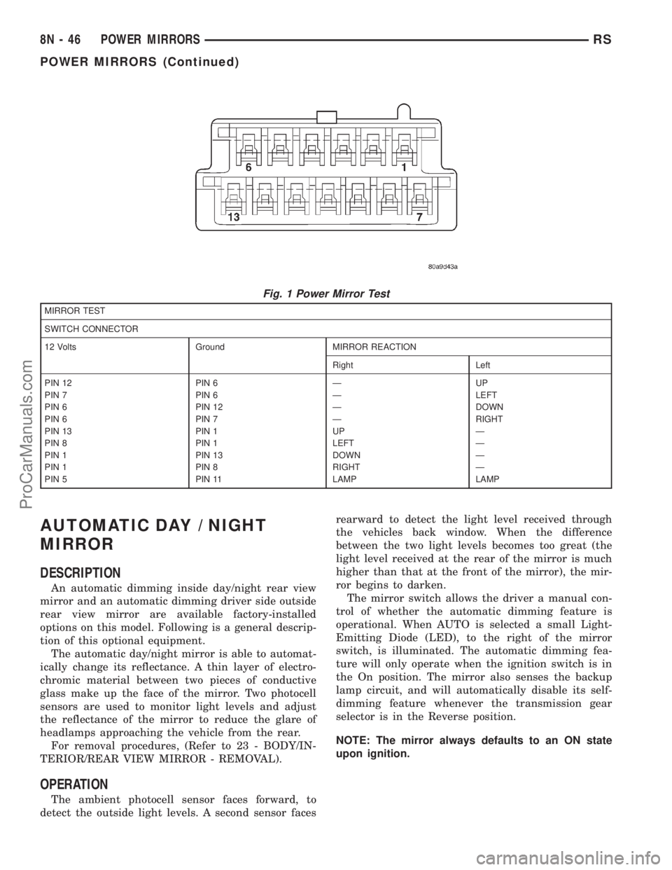
(3) Using two jumper wires:
²Connect one to a 12-volt source
²Connect the other to a good body ground
²Refer to the Mirror Test Chart for wire hookups
at the switch connector (Fig. 1).
(4) If results shown in table are not obtained,
check for broken or shorted circuit, or replace mirror
assembly as necessary.
RSPOWER MIRRORS8N-45
ProCarManuals.com
Page 559 of 2321
AUTOMATIC DAY / NIGHT
MIRROR
DESCRIPTION
An automatic dimming inside day/night rear view
mirror and an automatic dimming driver side outside
rear view mirror are available factory-installed
options on this model. Following is a general descrip-
tion of this optional equipment.
The automatic day/night mirror is able to automat-
ically change its reflectance. A thin layer of electro-
chromic material between two pieces of conductive
glass make up the face of the mirror. Two photocell
sensors are used to monitor light levels and adjust
the reflectance of the mirror to reduce the glare of
headlamps approaching the vehicle from the rear.
For removal procedures, (Refer to 23 - BODY/IN-
TERIOR/REAR VIEW MIRROR - REMOVAL).
OPERATION
The ambient photocell sensor faces forward, to
detect the outside light levels. A second sensor facesrearward to detect the light level received through
the vehicles back window. When the difference
between the two light levels becomes too great (the
light level received at the rear of the mirror is much
higher than that at the front of the mirror), the mir-
ror begins to darken.
The mirror switch allows the driver a manual con-
trol of whether the automatic dimming feature is
operational. When AUTO is selected a small Light-
Emitting Diode (LED), to the right of the mirror
switch, is illuminated. The automatic dimming fea-
ture will only operate when the ignition switch is in
the On position. The mirror also senses the backup
lamp circuit, and will automatically disable its self-
dimming feature whenever the transmission gear
selector is in the Reverse position.
NOTE: The mirror always defaults to an ON state
upon ignition.
Fig. 1 Power Mirror Test
MIRROR TEST
SWITCH CONNECTOR
12 Volts Ground MIRROR REACTION
Right Left
PIN 12 PIN 6 Ð UP
PIN 7 PIN 6 Ð LEFT
PIN 6 PIN 12 Ð DOWN
PIN 6 PIN 7 Ð RIGHT
PIN 13 PIN 1 UP Ð
PIN 8 PIN 1 LEFT Ð
PIN 1 PIN 13 DOWN Ð
PIN 1 PIN 8 RIGHT Ð
PIN 5 PIN 11 LAMP LAMP
8N - 46 POWER MIRRORSRS
POWER MIRRORS (Continued)
ProCarManuals.com
Page 560 of 2321
The driver side automatic dimming mirror is stan-
dard with the automatic dimming inside mirror. The
signal to control the dimming of that mirror is gen-
erated by the automatic day/night inside rear view
mirror circuitry. That signal is then delivered to the
driver side outside rear view mirror on a hard wired
circuit.
The automatic day/night mirror cannot be
repaired. If faulty or damaged, the entire inside rear
view mirror assembly must be replaced.
DIAGNOSIS AND TESTING - AUTOMATIC
DAY/NIGHT MIRROR
For circuit descriptions and diagrams, refer to the
appropriate wiring information. The wiring informa-
tion includes wiring diagrams, proper wire and con-
nector repair procedures, details of wire harness
routing and retention, connector pin-out information
and location views for the various wire harness con-
nectors, splices and grounds.
(1) Check the fuse in the intelligent power module.
If OK, go to Step 2. If not OK, repair the shorted cir-
cuit or component as required and replace the faulty
fuse.
(2) Turn the ignition switch to the On position.
Check for battery voltage at the fuse in the intelli-
gent power module. If OK, go to Step 3. If not OK,
repair the open circuit to the ignition switch as
required.
(3) Unplug the wire harness connector from the
automatic day/night mirror. Check for battery voltage
at the fused ignition switch output circuit cavity of
the automatic day/night mirror wire harness connec-
tor. If OK, go to Step 4. If not OK, repair the open
circuit to the junction block as required.
(4) Turn the ignition switch to the Off position.
Check for continuity between the ground circuit cav-
ity of the automatic day/night mirror wire harness
connector and a good ground. There should be conti-
nuity. If OK, go to Step 5. If not OK, repair the cir-
cuit to ground as required.
(5) Turn the ignition switch to the On position. Set
the parking brake. Place the transmission gear selec-
tor lever in the Reverse position. Check for battery
voltage at the backup lamp switch output circuit cav-ity of the automatic day/night mirror wire harness
connector. If voltage is present, reinstall the auto-
matic day/night mirror wire harness connector and
go to Step 6. If not OK, repair the open circuit as
required.
(6) Place the transmission gear selector lever in
the Neutral position. Place the automatic day/night
mirror switch in the On (LED in the switch is
lighted) position. Cover the forward facing ambient
photocell sensor to keep out any ambient light.
NOTE: The ambient photocell sensor must be cov-
ered completely, so that no light reaches the sen-
sor. Use a finger pressed tightly against the sensor,
or cover the sensor completely with electrical tape.
(7) Shine a light into the rearward facing head-
lamp photocell sensor. The automatic day/night mir-
ror should darken. The automatic day/night mirror
should darken within 2 minutes if testing for the
first time. For immediate response, turn the vehicle
OFF and back ON with the forward-facing light sen-
sor still covered. This defeats the day-detect logic. If
OK, go to Step 8. If not OK, replace the faulty mirror
unit.
(8) With the mirror darkened, place the transmis-
sion gear selector lever in the Reverse position. The
automatic day/night mirror should return to its nor-
mal reflectance. If not OK, replace the faulty mirror
unit.
Bench testing both mirrors can be done, of care is
exercised. For an inside mirror, the pin closest to he
mount is 12V (+), the next is 12V (-). The third is
reverse override. The fourth is outside mirror (+),
and the fifth is outside mirror (-).Do not apply 12
volts to the fourth and fifth pins.With 12 volts
on pins 1 and 2, the mirror can be tested by blocking
the rear sensor and shining a light into the forward
sensor. For an outside mirror, there is a 2±pin con-
nector. Applying 1.2 volts will cause the mirror to
dim. If the mirror does not dim, the entire glass
assembly can be replaced just as it is when the glass
is broken.
WARNING: Do not apply 12 volts to the outside mir-
ror. Damage to the mirror will result.
RSPOWER MIRRORS8N-47
AUTOMATIC DAY / NIGHT MIRROR (Continued)
ProCarManuals.com