DODGE TOWN AND COUNTRY 2001 Service Manual
Manufacturer: DODGE, Model Year: 2001, Model line: TOWN AND COUNTRY, Model: DODGE TOWN AND COUNTRY 2001Pages: 2321, PDF Size: 68.09 MB
Page 571 of 2321
POWER SEAT TRACK
DESCRIPTION
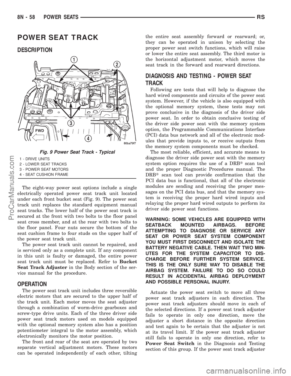
The eight-way power seat options include a single
electrically operated power seat track unit located
under each front bucket seat (Fig. 9). The power seat
track unit replaces the standard equipment manual
seat tracks. The lower half of the power seat track is
secured at the front with two bolts to the floor panel
seat cross member, and at the rear with two bolts to
the floor panel. Four nuts secure the bottom of the
seat cushion frame to four studs on the upper half of
the power seat track unit.
The power seat track unit cannot be repaired, and
is serviced only as a complete unit. If any component
in this unit is faulty or damaged, the entire power
seat track unit must be replaced. Refer toBucket
Seat Track Adjusterin the Body section of the ser-
vice manual for the procedure.
OPERATION
The power seat track unit includes three reversible
electric motors that are secured to the upper half of
the track unit. Each motor moves the seat adjuster
through a combination of worm-drive gearboxes and
screw-type drive units. Each of the three driver side
power seat track motors used on models equipped
with the optional memory system also has a position
potentiometer integral to the motor assembly, which
electronically monitors the motor position.
The front and rear of the seat are operated by two
separate vertical adjustment motors. These motors
can be operated independently of each other, tiltingthe entire seat assembly forward or rearward; or,
they can be operated in unison by selecting the
proper power seat switch functions, which will raise
or lower the entire seat assembly. The third motor is
the horizontal adjustment motor, which moves the
seat track in the forward and rearward directions.
DIAGNOSIS AND TESTING - POWER SEAT
TRACK
Following are tests that will help to diagnose the
hard wired components and circuits of the power seat
system. However, if the vehicle is also equipped with
the optional memory system, these tests may not
prove conclusive in the diagnosis of the driver side
power seat. In order to obtain conclusive testing of
the driver side power seat with the memory system
option, the Programmable Communications Interface
(PCI) data bus network and all of the electronic mod-
ules that provide inputs to, or receive outputs from
the memory system components must be checked.
The most reliable, efficient, and accurate means to
diagnose the driver side power seat with the memory
system option requires the use of a DRBtscan tool
and the proper Diagnostic Procedures manual. The
DRBtscan tool can provide confirmation that the
PCI data bus is functional, that all of the electronic
modules are sending and receiving the proper mes-
sages on the PCI data bus, and that the memory sys-
tem is receiving the proper hard wired inputs and
relaying the proper hard wired outputs to perform its
driver side power seat functions.
WARNING: SOME VEHICLES ARE EQUIPPED WITH
SEATBACK MOUNTED AIRBAGS. BEFORE
ATTEMPTING TO DIAGNOSE OR SERVICE ANY
SEAT OR POWER SEAT SYSTEM COMPONENT
YOU MUST FIRST DISCONNECT AND ISOLATE THE
BATTERY NEGATIVE CABLE. THEN WAIT TWO MIN-
UTES FOR THE SYSTEM CAPACITOR TO DIS-
CHARGE BEFORE FURTHER SYSTEM SERVICE.
THIS IS THE ONLY SURE WAY TO DISABLE THE
AIRBAG SYSTEM. FAILURE TO DO SO COULD
RESULT IN ACCIDENTAL AIRBAG DEPLOYMENT
AND POSSIBLE PERSONAL INJURY.
Actuate the power seat switch to move all three
power seat track adjusters in each direction. The
power seat track adjusters should move in each of
the selected directions. If a power seat track adjuster
fails to operate in only one direction, move the
adjuster a short distance in the opposite direction
and test again to be certain that the adjuster is not
at its travel limit. If the power seat track adjuster
still fails to operate in only one direction, refer to
Power Seat Switchin the Diagnosis and Testing
section of this group. If the power seat track adjuster
Fig. 9 Power Seat Track - Typical
1 - DRIVE UNITS
2 - LOWER SEAT TRACKS
3 - POWER SEAT MOTORS
4 - SEAT CUSHION FRAME
8N - 58 POWER SEATSRS
ProCarManuals.com
Page 572 of 2321
fails to operate in more than one direction, perform
the following tests. For complete circuit diagrams,
refer toPower Seatin Wiring Diagrams.
(1) Check the power seat circuit breaker under the
seat. If OK, go to Step 2. If not OK, replace the
faulty power seat circuit breaker.
(2) Check for battery voltage at the power seat cir-
cuit breaker under the seat. If OK, go to Step 3. If
not OK, repair the open fused B(+) circuit to the fuse
in the Intelligent Power Module as required.
(3) Remove the outboard seat cushion side shield
from the seat. Disconnect the seat wire harness con-
nector from the power seat switch connector recepta-
cle. Check for battery voltage at the fused B(+)
circuit cavity of the power seat wire harness connec-
tor for the power seat switch. If OK, go to Step 4. If
not OK, repair the open fused B(+) circuit to the
power seat circuit breaker under the seat as
required.
(4) Check for continuity between the ground cir-
cuit cavity of the power seat wire harness connector
for the power seat switch and a good ground. There
should be continuity. If OK, go to Step 5. If not OK,
repair the open ground circuit to ground as required.
(5) Test the power seat switch. Refer toPower
Seat Switchin the Diagnosis and Testing section of
this group. If the switch tests OK, test the circuits of
the power seat wire harness between the inoperative
power seat track adjuster motor and the power seat
switch for shorts or opens. If the circuits check OK,
replace the faulty power seat track unit. If the cir-
cuits are not OK, repair the power seat wire harness
as required.
REMOVAL
WARNING: SOME VEHICLES ARE EQUIPPED WITH
SEATBACK MOUNTED AIRBAGS. BEFORE
ATTEMPTING TO DIAGNOSE OR SERVICE ANY
SEAT OR POWER SEAT SYSTEM COMPONENT
YOU MUST FIRST DISCONNECT AND ISOLATE THE
BATTERY NEGATIVE CABLE. THEN WAIT TWO MIN-
UTES FOR THE SYSTEM CAPACITOR TO DIS-
CHARGE BEFORE FURTHER SYSTEM SERVICE.
THIS IS THE ONLY SURE WAY TO DISABLE THE
AIRBAG SYSTEM. FAILURE TO DO SO COULD
RESULT IN ACCIDENTAL AIRBAG DEPLOYMENT
AND POSSIBLE PERSONAL INJURY.(1) Remove the appropriate seat from the vehicle.
Refer to Body for the procedure.
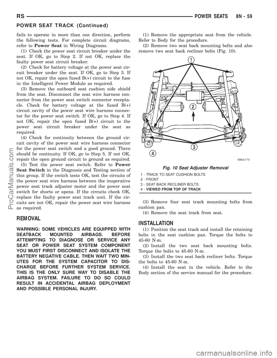
(2) Remove two seat back mounting bolts and also
remove two seat back recliner bolts (Fig. 10).
(3) Remove four seat track mounting bolts from
cushion pan.
(4) Remove the seat track from seat.
INSTALLATION
(1) Position the seat track and install the retaining
bolts in the seat cushion pan. Torque the bolts to
45-60 N´m.
(2) Install the two seat back mounting bolts.
Torque the bolts to 45-60 N´m.
(3) Install the two seat back recliner bolts. Torque
the bolts to 45-60 N´m.
(4) Install the seat in the vehicle. Refer to the
Body section of the service manual for the procedure.
Fig. 10 Seat Adjuster Removal
1 - TRACK TO SEAT CUSHION BOLTS
2 - FRONT
3 - SEAT BACK RECLINER BOLTS
4-VIEWED FROM TOP OF TRACK
RSPOWER SEATS8N-59
POWER SEAT TRACK (Continued)
ProCarManuals.com
Page 573 of 2321
POWER WINDOWS
TABLE OF CONTENTS
page page
POWER WINDOWS
DESCRIPTION...........................60
OPERATION.............................60
DIAGNOSIS AND TESTING.................60
POWER WINDOWS.....................60
VENT WINDOW MOTOR
DIAGNOSIS AND TESTING.................61
VENT WINDOW MOTOR.................61
REMOVAL..............................61INSTALLATION...........................62
WINDOW MOTOR
REMOVAL..............................62
WINDOW SWITCH
DIAGNOSIS AND TESTING.................62
WINDOW SWITCH......................62
REMOVAL..............................63
INSTALLATION...........................63
POWER WINDOWS
DESCRIPTION
The Power Window System is activated through
switches mounted on the driver and passenger door
panels.
OPERATION
Front door window lift motors use permanent type
magnets. The B+ and ground applied at the motor ter-
minal pins will cause the motor to rotate in one direc-
tion. Reversing current through the motor terminals
will cause the motor to rotate in the opposite direction.
The power window motors ground through the
master switch in the driver door by a black wire
attached to the left cowl panel. Refer to the appropri-
ate wiring information. The wiring information
includes wiring diagrams, proper wire and connector
repair procedures, details of wire harness routing
and retention, connector pin-out information and
location views for the various wire harness connec-
tors, splices and grounds.
The power rear vent windows, if equipped, are oper-
ated by switches mounted in the driver door switch
bezel. A separate switch is used for each window. Per-
manent magnet type motors connected to a crank sys-
tem are used to open and close the rear vent windows.
A battery positive and negative connection to either of
the two motor terminals will cause the motor to rotate
in one direction. Reversing current through these same
two connections will cause the motor to rotate in the
opposite direction. Refer to the appropriate wiring infor-
mation. The wiring information includes wiring dia-
grams, proper wire and connector repair procedures,
details of wire harness routing and retention, connector
pin-out information and location views for the various
wire harness connectors, splices and grounds.
DIAGNOSIS AND TESTING - POWER
WINDOWS
POWER WINDOW MOTOR TEST
If the power window motor is receiving proper cur-
rent and ground and does not operate, proceed with
motor test. Refer to the appropriate wiring informa-
tion. The wiring information includes wiring dia-
grams, proper wire and connector repair procedures,
details of wire harness routing and retention, connec-
tor pin-out information and location views for the
various wire harness connectors, splices and grounds.
(1) Remove front door trim panel and sound pad as
necessary to gain access to power window motor wire
connector, (Refer to 23 - BODY/DOOR - FRONT/
TRIM PANEL - REMOVAL).
(2) Disconnect power window motor wire connector
from door harness.
(3) Using two jumper wires, connect one to a bat-
tery (+) source and the other to a good ground (-).
(4) Connect the Negative (-) jumper probe to one of
the motor connector terminals.
(5) Momentarily touch the Positive (+) jumper
probe to the other motor connector terminal.
When positive probe is connected the motor should
rotate in one direction to either move window up or
down. If window is all the way up or down the motor
will grunt and the inner door panel will flex when
actuated in that one direction.
(6) Reverse jumper probes at the motor connector
terminals and window should now move in opposite
direction. If window does not move or grunt, replace
the motor.
If window moved completely up or down, reverse
the jumper probes and cycle window to the opposite
position to verify full operation.
If motor grunts and does not move, verify that reg-
ulator is not binding.
8N - 60 POWER WINDOWSRS
ProCarManuals.com
Page 574 of 2321
WIRING VOLTAGE TEST
The following wiring test determines whether or
not voltage is continuous through the body harness
to switch.
(1) Remove the power window switch and bezel
assembly from the driver door. (Refer to 8 - ELEC-
TRICAL/POWER WINDOWS/POWER WINDOW
SWITCH - REMOVAL).
(2) Disconnect wire connector from back of power
window switch.
(3) Switch ignition ON position.
(4) Connect the clip end of a 12 volt test light to
Pin 13 in door harness connector at the window
switch. Touch the test light probe to Pin 9 and then
to Pin 11.
²If the test light illuminates, the wiring circuit
between the battery and switch is OK.
²If the lamp does not illuminate, first check the
25 amp circuit breaker attached to the electrical dis-
tribution wiring bracket. If the circuit breaker is OK,
then check the 40 amp fuse (#28) in the Intelligent
Power Module. If both components are OK, then
check for a broken wire.
²Refer to the appropriate wiring information.
The wiring information includes wiring diagrams,
proper wire and connector repair procedures, details
of wire harness routing and retention, connector pin-
out information and location views for the various
wire harness connectors, splices and grounds.
VENT WINDOW MOTOR
DIAGNOSIS AND TESTING - VENT WINDOW
MOTOR
If the power vent window motor is receiving proper
current and ground and does not operate proceed
with motor test. Refer to the appropriate wiring
information. The wiring information includes wiring
diagrams, proper wire and connector repair proce-
dures, details of wire harness routing and retention,
connector pin-out information and location views for
the various wire harness connectors, splices and
grounds.
(1) Remove D-pillar trim panel necessary to gain
access to power vent window motor wire connector,
(Refer to 23 - BODY/INTERIOR/LEFT D-PILLAR
TRIM PANEL - REMOVAL) or (Refer to 23 - BODY/
INTERIOR/RIGHT D-PILLAR TRIM PANEL -
REMOVAL).
(2) Disconnect power vent window motor wire con-
nector from body harness.
(3) Using two jumper wires, connect one to a bat-
tery (+) source and the other to a good ground (-).
(4) Connect the Negative (-) jumper probe to one of
the motor connector terminals.(5) Momentarily touch the Positive (+) jumper
probe to the other motor connector terminal.
When positive probe is connected the motor should
rotate in one direction to either move window open or
closed. If window is all the way open or closed the
motor will grunt and the crank system will flex when
actuated in that one direction.
Reverse jumper probes at the motor connector ter-
minals and window should now move in opposite
direction. If window does not move or grunt, replace
the motor.
If window moved completely open or closed, reverse
the jumper probes and cycle window to the opposite
position to verify full operation.
If motor grunts and does not move, verify that
crank system is not binding.
REMOVAL
(1) Disconnect and isolate the battery negative
cable.
(2) Remove D-pillar trim panel. (Refer to 23 -
BODY/INTERIOR/LEFT D-PILLAR TRIM PANEL -
REMOVAL) or (Refer to 23 - BODY/INTERIOR/
RIGHT D-PILLAR TRIM PANEL - REMOVAL).
(3) Disconnect wire connector from power vent
motor.
(4) Using a flat bladed tool, carefully lift the circu-
lar actuator link tab. Remove link from window ball
socket.
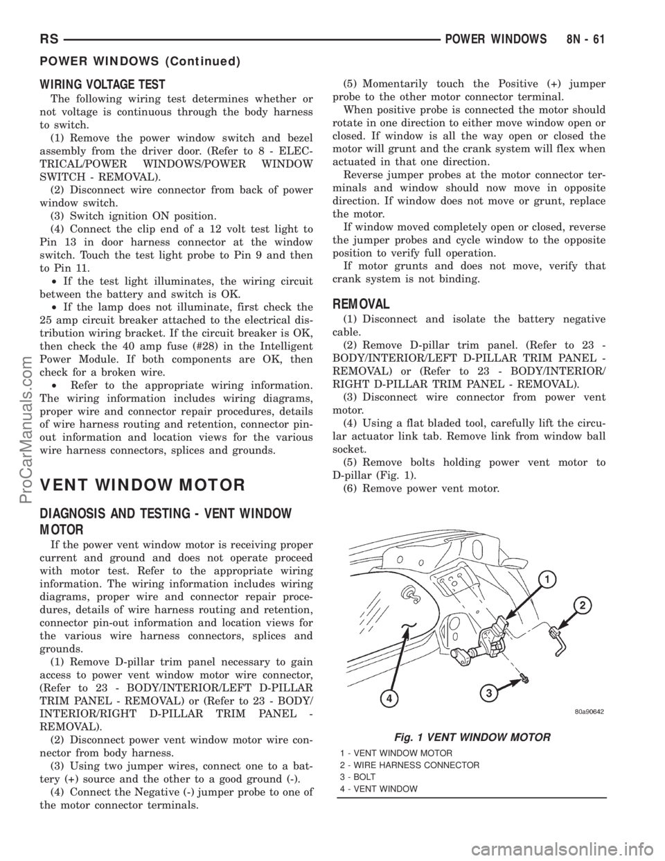
(5) Remove bolts holding power vent motor to
D-pillar (Fig. 1).
(6) Remove power vent motor.
Fig. 1 VENT WINDOW MOTOR
1 - VENT WINDOW MOTOR
2 - WIRE HARNESS CONNECTOR
3 - BOLT
4 - VENT WINDOW
RSPOWER WINDOWS8N-61
POWER WINDOWS (Continued)
ProCarManuals.com
Page 575 of 2321
INSTALLATION
(1) Obtain new vent window motor.
(2) Snap the actuator link socket onto the quarter
window ball socket. Using a soft rubber mallet, push
the circular link tab flush with link surface.
(3) Install bolts holding power vent motor to D-pil-
lar.
(4) Reconnect wire connector to power vent motor.
(5) Reconnect the battery negative cable.
(6) Cycle quarter window open/close to verify func-
tion.
(7) Install D-pillar trim panel.
WINDOW MOTOR
REMOVAL
The window motor is incorporated into the window
regulator assembly. If the window motor requires
replacement, the window regulator must be replaced.
(Refer to 23 - BODY/DOOR - FRONT/WINDOW
REGULATOR - REMOVAL).
WINDOW SWITCH
DIAGNOSIS AND TESTING - WINDOW SWITCH
(1) Remove the desired switch to be tested from
the door trim panel. Driver's side (master) or passen-
ger side. (Refer to 8 - ELECTRICAL/POWER WIN-
DOWS/POWER WINDOW SWITCH - REMOVAL).(2) Using an ohmmeter, Test driver door switch for
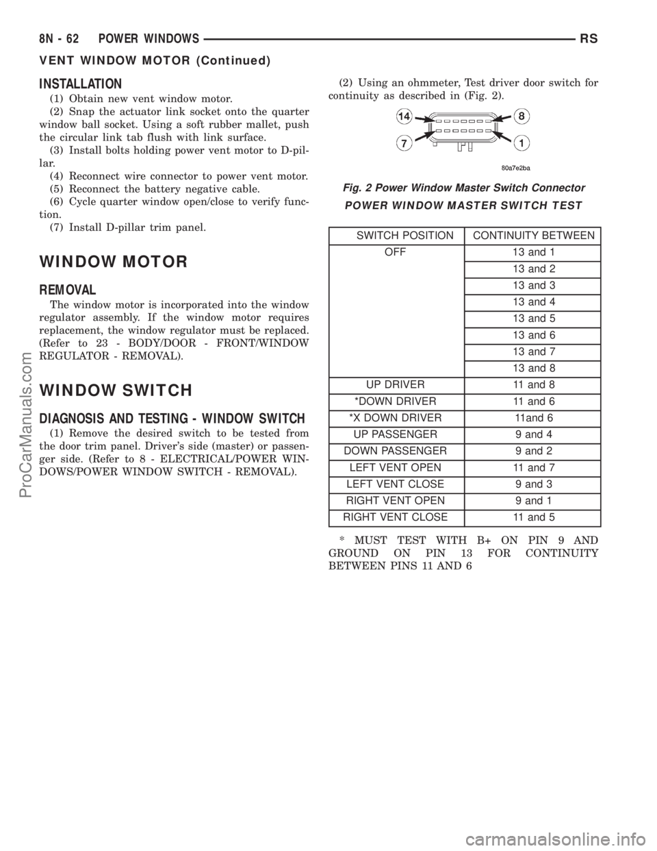
continuity as described in (Fig. 2).
POWER WINDOW MASTER SWITCH TEST
SWITCH POSITION CONTINUITY BETWEEN
OFF 13 and 1
13 and 2
13 and 3
13 and 4
13 and 5
13 and 6
13 and 7
13 and 8
UP DRIVER 11 and 8
*DOWN DRIVER 11 and 6
*X DOWN DRIVER 11and 6
UP PASSENGER 9 and 4
DOWN PASSENGER 9 and 2
LEFT VENT OPEN 11 and 7
LEFT VENT CLOSE 9 and 3
RIGHT VENT OPEN 9 and 1
RIGHT VENT CLOSE 11 and 5
* MUST TEST WITH B+ ON PIN 9 AND
GROUND ON PIN 13 FOR CONTINUITY
BETWEEN PINS 11 AND 6
Fig. 2 Power Window Master Switch Connector
8N - 62 POWER WINDOWSRS
VENT WINDOW MOTOR (Continued)
ProCarManuals.com
Page 576 of 2321
(3) If the result are not OK, replace the driver side
window lift switch.
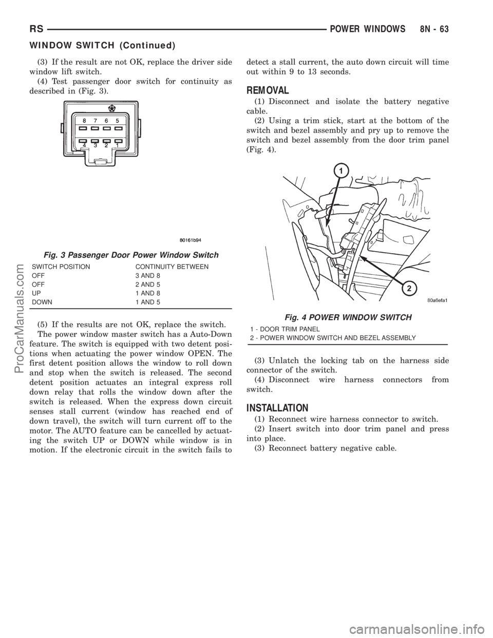
(4) Test passenger door switch for continuity as
described in (Fig. 3).
(5) If the results are not OK, replace the switch.
The power window master switch has a Auto-Down
feature. The switch is equipped with two detent posi-
tions when actuating the power window OPEN. The
first detent position allows the window to roll down
and stop when the switch is released. The second
detent position actuates an integral express roll
down relay that rolls the window down after the
switch is released. When the express down circuit
senses stall current (window has reached end of
down travel), the switch will turn current off to the
motor. The AUTO feature can be cancelled by actuat-
ing the switch UP or DOWN while window is in
motion. If the electronic circuit in the switch fails todetect a stall current, the auto down circuit will time
out within 9 to 13 seconds.
REMOVAL
(1) Disconnect and isolate the battery negative
cable.
(2) Using a trim stick, start at the bottom of the
switch and bezel assembly and pry up to remove the
switch and bezel assembly from the door trim panel
(Fig. 4).
(3) Unlatch the locking tab on the harness side
connector of the switch.
(4) Disconnect wire harness connectors from
switch.
INSTALLATION
(1) Reconnect wire harness connector to switch.
(2) Insert switch into door trim panel and press
into place.
(3) Reconnect battery negative cable.
Fig. 3 Passenger Door Power Window Switch
SWITCH POSITION CONTINUITY BETWEEN
OFF 3 AND 8
OFF 2 AND 5
UP 1 AND 8
DOWN 1 AND 5
Fig. 4 POWER WINDOW SWITCH
1 - DOOR TRIM PANEL
2 - POWER WINDOW SWITCH AND BEZEL ASSEMBLY
RSPOWER WINDOWS8N-63
WINDOW SWITCH (Continued)
ProCarManuals.com
Page 577 of 2321

ProCarManuals.com
Page 578 of 2321
POWER SYSTEMS
TABLE OF CONTENTS
page page
POWER FOLDAWAY MIRROR SWITCH
DESCRIPTION............................1
OPERATION.............................1REMOVAL...............................1
INSTALLATION............................2
POWER FOLDAWAY MIRROR
SWITCH
DESCRIPTION
These vehicles may be equipped with Power Fold-
away Mirrors. This feature allows both the driver
and passenger side view mirrors to fold inward
(retract) on demand. The vehicle has an additional
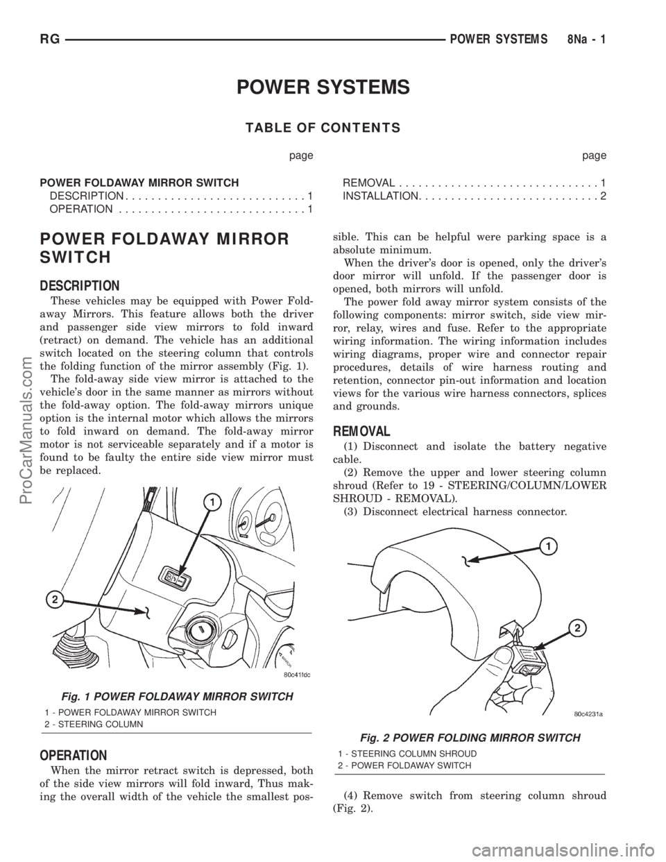
switch located on the steering column that controls
the folding function of the mirror assembly (Fig. 1).
The fold-away side view mirror is attached to the
vehicle's door in the same manner as mirrors without
the fold-away option. The fold-away mirrors unique
option is the internal motor which allows the mirrors
to fold inward on demand. The fold-away mirror
motor is not serviceable separately and if a motor is
found to be faulty the entire side view mirror must
be replaced.
OPERATION
When the mirror retract switch is depressed, both
of the side view mirrors will fold inward, Thus mak-
ing the overall width of the vehicle the smallest pos-sible. This can be helpful were parking space is a
absolute minimum.
When the driver's door is opened, only the driver's
door mirror will unfold. If the passenger door is
opened, both mirrors will unfold.
The power fold away mirror system consists of the
following components: mirror switch, side view mir-
ror, relay, wires and fuse. Refer to the appropriate
wiring information. The wiring information includes
wiring diagrams, proper wire and connector repair
procedures, details of wire harness routing and
retention, connector pin-out information and location
views for the various wire harness connectors, splices
and grounds.
REMOVAL
(1) Disconnect and isolate the battery negative
cable.
(2) Remove the upper and lower steering column
shroud (Refer to 19 - STEERING/COLUMN/LOWER
SHROUD - REMOVAL).
(3) Disconnect electrical harness connector.
(4) Remove switch from steering column shroud
(Fig. 2).
Fig. 1 POWER FOLDAWAY MIRROR SWITCH
1 - POWER FOLDAWAY MIRROR SWITCH
2 - STEERING COLUMN
Fig. 2 POWER FOLDING MIRROR SWITCH
1 - STEERING COLUMN SHROUD
2 - POWER FOLDAWAY SWITCH
RGPOWER SYSTEMS8Na-1
ProCarManuals.com
Page 579 of 2321
INSTALLATION
(1) Install switch to steering column shroud.
(2) Connect wire harness connector.
(3) Install the upper and lower steering column
shroud (Refer to 19 - STEERING/COLUMN/LOWER
SHROUD - INSTALLATION).
(4) Connect the battery negative cable.
8Na - 2 POWER SYSTEMSRG
POWER FOLDAWAY MIRROR SWITCH (Continued)
ProCarManuals.com
Page 580 of 2321
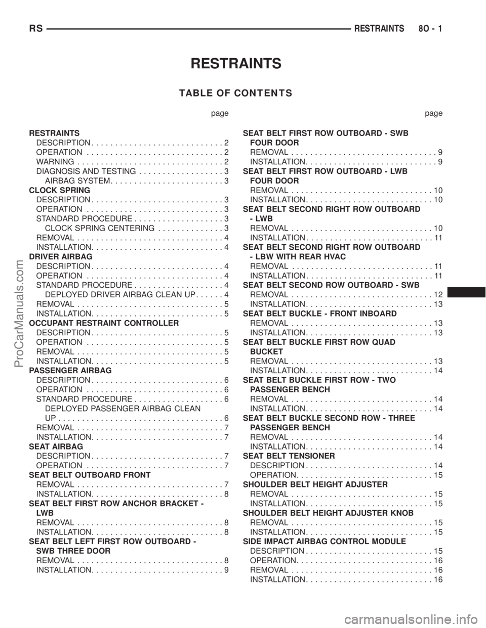
RESTRAINTS
TABLE OF CONTENTS
page page
RESTRAINTS
DESCRIPTION............................2
OPERATION.............................2
WARNING...............................2
DIAGNOSIS AND TESTING..................3
AIRBAG SYSTEM........................3
CLOCK SPRING
DESCRIPTION............................3
OPERATION.............................3
STANDARD PROCEDURE...................3
CLOCK SPRING CENTERING..............3
REMOVAL...............................4
INSTALLATION............................4
DRIVER AIRBAG
DESCRIPTION............................4
OPERATION.............................4
STANDARD PROCEDURE...................4
DEPLOYED DRIVER AIRBAG CLEAN UP......4
REMOVAL...............................5
INSTALLATION............................5
OCCUPANT RESTRAINT CONTROLLER
DESCRIPTION............................5
OPERATION.............................5
REMOVAL...............................5
INSTALLATION............................5
PASSENGER AIRBAG
DESCRIPTION............................6
OPERATION.............................6
STANDARD PROCEDURE...................6
DEPLOYED PASSENGER AIRBAG CLEAN
UP...................................6
REMOVAL...............................7
INSTALLATION............................7
SEAT AIRBAG
DESCRIPTION............................7
OPERATION.............................7
SEAT BELT OUTBOARD FRONT
REMOVAL...............................7
INSTALLATION............................8
SEAT BELT FIRST ROW ANCHOR BRACKET -
LW B
REMOVAL...............................8
INSTALLATION............................8
SEAT BELT LEFT FIRST ROW OUTBOARD -
SWB THREE DOOR
REMOVAL...............................8
INSTALLATION............................9SEAT BELT FIRST ROW OUTBOARD - SWB
FOUR DOOR
REMOVAL...............................9
INSTALLATION............................9
SEAT BELT FIRST ROW OUTBOARD - LWB
FOUR DOOR
REMOVAL..............................10
INSTALLATION...........................10
SEAT BELT SECOND RIGHT ROW OUTBOARD
-LWB
REMOVAL..............................10
INSTALLATION...........................11
SEAT BELT SECOND RIGHT ROW OUTBOARD
- LBW WITH REAR HVAC
REMOVAL..............................11
INSTALLATION...........................11
SEAT BELT SECOND ROW OUTBOARD - SWB
REMOVAL..............................12
INSTALLATION...........................13
SEAT BELT BUCKLE - FRONT INBOARD
REMOVAL..............................13
INSTALLATION...........................13
SEAT BELT BUCKLE FIRST ROW QUAD
BUCKET
REMOVAL..............................13
INSTALLATION...........................14
SEAT BELT BUCKLE FIRST ROW - TWO
PASSENGER BENCH
REMOVAL..............................14
INSTALLATION...........................14
SEAT BELT BUCKLE SECOND ROW - THREE
PASSENGER BENCH
REMOVAL..............................14
INSTALLATION...........................14
SEAT BELT TENSIONER
DESCRIPTION...........................14
OPERATION.............................15
SHOULDER BELT HEIGHT ADJUSTER
REMOVAL..............................15
INSTALLATION...........................15
SHOULDER BELT HEIGHT ADJUSTER KNOB
REMOVAL..............................15
INSTALLATION...........................15
SIDE IMPACT AIRBAG CONTROL MODULE
DESCRIPTION...........................15
OPERATION.............................16
REMOVAL..............................16
INSTALLATION...........................16
RSRESTRAINTS8O-1
ProCarManuals.com