Freeze plugs DODGE TOWN AND COUNTRY 2001 Service Manual
[x] Cancel search | Manufacturer: DODGE, Model Year: 2001, Model line: TOWN AND COUNTRY, Model: DODGE TOWN AND COUNTRY 2001Pages: 2321, PDF Size: 68.09 MB
Page 271 of 2321

- 124 kPa (14 - 18 psi). This air is replaced with cool-
ant from the coolant bottle.
NOTE: Deaeration does not occur at engine idleÐ
higher engine speeds are required. Normal driving
will deaerate cooling system.
To effectively deaerate the system, multiple ther-
mal cycles of the system may be required.
STANDARD PROCEDURE - COOLING SYSTEM
DRAINING
WARNING: DO NOT REMOVE OR LOOSEN THE
COOLANT PRESSURE CAP, CYLINDER BLOCK
DRAIN PLUGS, OR THE DRAINCOCK WHEN THE
SYSTEM IS HOT AND UNDER PRESSURE
BECAUSE SERIOUS BURNS FROM THE COOLANT
CAN OCCUR.
(1)Without removing radiator pressure cap
and with system not under pressure, open the
draincock. The draincock is located on the lower left
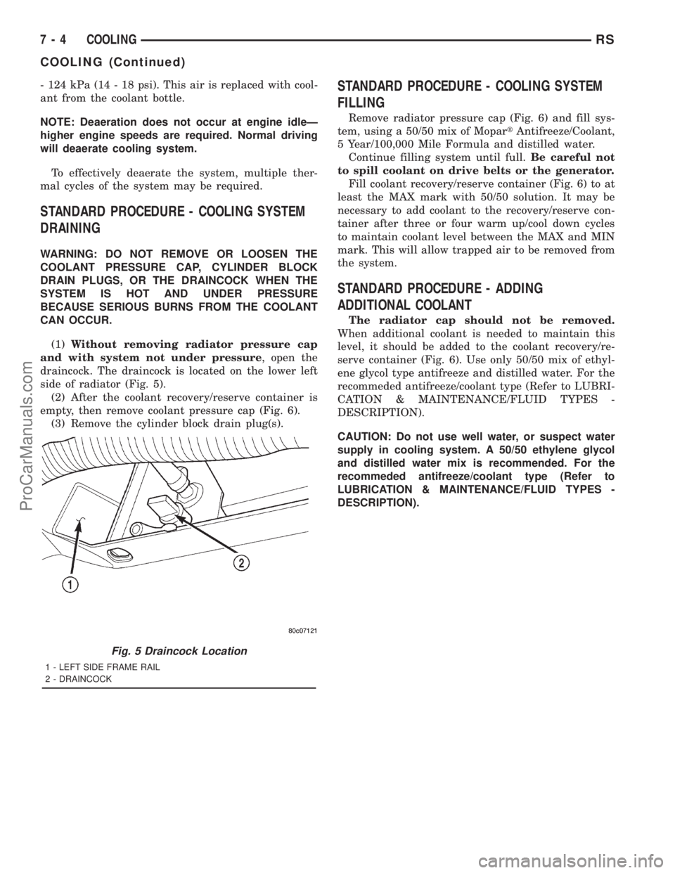
side of radiator (Fig. 5).
(2) After the coolant recovery/reserve container is
empty, then remove coolant pressure cap (Fig. 6).
(3) Remove the cylinder block drain plug(s).
STANDARD PROCEDURE - COOLING SYSTEM
FILLING
Remove radiator pressure cap (Fig. 6) and fill sys-
tem, using a 50/50 mix of MopartAntifreeze/Coolant,
5 Year/100,000 Mile Formula and distilled water.
Continue filling system until full.Be careful not
to spill coolant on drive belts or the generator.
Fill coolant recovery/reserve container (Fig. 6) to at
least the MAX mark with 50/50 solution. It may be
necessary to add coolant to the recovery/reserve con-
tainer after three or four warm up/cool down cycles
to maintain coolant level between the MAX and MIN
mark. This will allow trapped air to be removed from
the system.
STANDARD PROCEDURE - ADDING
ADDITIONAL COOLANT
The radiator cap should not be removed.
When additional coolant is needed to maintain this
level, it should be added to the coolant recovery/re-
serve container (Fig. 6). Use only 50/50 mix of ethyl-
ene glycol type antifreeze and distilled water. For the
recommeded antifreeze/coolant type (Refer to LUBRI-
CATION & MAINTENANCE/FLUID TYPES -
DESCRIPTION).
CAUTION: Do not use well water, or suspect water
supply in cooling system. A 50/50 ethylene glycol
and distilled water mix is recommended. For the
recommeded antifreeze/coolant type (Refer to
LUBRICATION & MAINTENANCE/FLUID TYPES -
DESCRIPTION).
Fig. 5 Draincock Location
1 - LEFT SIDE FRAME RAIL
2 - DRAINCOCK
7 - 4 COOLINGRS
COOLING (Continued)
ProCarManuals.com
Page 323 of 2321

STANDARD PROCEDURE - COOLANT LEVEL
CHECK
NOTE: Do not remove pressure/vent cap for routine
coolant level inspections.
The coolant reserve system provides a quick visual
method for determining the coolant level without
removing the pressure/vent cap.With the engine
cold and not running,simply observe the level of
the coolant in the coolant recovery pressure container
(Fig. 2). The coolant level should be between the MIN
and MAX marks.
STANDARD PROCEDURE - REFILLING
COOLING SYSTEM
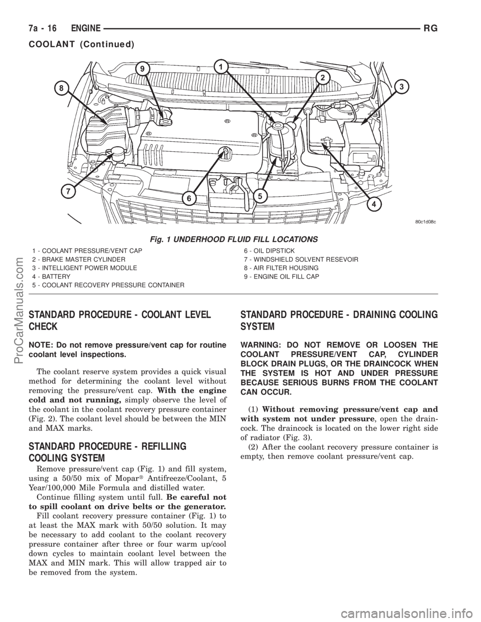
Remove pressure/vent cap (Fig. 1) and fill system,
using a 50/50 mix of MopartAntifreeze/Coolant, 5
Year/100,000 Mile Formula and distilled water.
Continue filling system until full.Be careful not
to spill coolant on drive belts or the generator.
Fill coolant recovery pressure container (Fig. 1) to
at least the MAX mark with 50/50 solution. It may
be necessary to add coolant to the coolant recovery
pressure container after three or four warm up/cool
down cycles to maintain coolant level between the
MAX and MIN mark. This will allow trapped air to
be removed from the system.
STANDARD PROCEDURE - DRAINING COOLING
SYSTEM
WARNING: DO NOT REMOVE OR LOOSEN THE
COOLANT PRESSURE/VENT CAP, CYLINDER
BLOCK DRAIN PLUGS, OR THE DRAINCOCK WHEN
THE SYSTEM IS HOT AND UNDER PRESSURE
BECAUSE SERIOUS BURNS FROM THE COOLANT
CAN OCCUR.
(1)Without removing pressure/vent cap and
with system not under pressure, open the drain-
cock. The draincock is located on the lower right side
of radiator (Fig. 3).
(2) After the coolant recovery pressure container is
empty, then remove coolant pressure/vent cap.
Fig. 1 UNDERHOOD FLUID FILL LOCATIONS
1 - COOLANT PRESSURE/VENT CAP
2 - BRAKE MASTER CYLINDER
3 - INTELLIGENT POWER MODULE
4 - BATTERY
5 - COOLANT RECOVERY PRESSURE CONTAINER6 - OIL DIPSTICK
7 - WINDSHIELD SOLVENT RESEVOIR
8 - AIR FILTER HOUSING
9 - ENGINE OIL FILL CAP
7a - 16 ENGINERG
COOLANT (Continued)
ProCarManuals.com
Page 2262 of 2321

through the rear evaporator when the rear air condi-
tioner is turned Off.
DIAGNOSIS AND TESTING - EXPANSION VALVE
WARNING: REFER TO THE APPLICABLE WARN-
INGS AND CAUTIONS FOR THIS SYSTEM BEFORE
PERFORMING THE FOLLOWING OPERATION.
(Refer to 24 - HEATING & AIR CONDITIONING/
PLUMBING - FRONT - WARNING - A/C PLUMBING)
and (Refer to 24 - HEATING & AIR CONDITIONING/
PLUMBING - FRONT - CAUTION - A/C PLUMBING).
NOTE: The expansion valve should only be tested
following testing of the compressor.
NOTE: Liquid CO
2is required to test the expansion
valve. This material is available from most welding
supply facilities. Liquid CO
2is also available from
companies which service and sell fire extinguish-
ers.
When testing the expansion valve, the work area
and the vehicle temperature must be 21É to 27É C
(70É to 85É F). To test the expansion valve:
(1) Connect a charging station or manifold gauge
set to the refrigerant system service ports. Verify the
refrigerant charge level.
(2) Close all doors, windows and vents to the pas-
senger compartment.
(3) Set the heater-air conditioner controls so that
the compressor is operating, the temperature control
is in the highest temperature position, the mode door
is directing the output to the floor outlets, and the
blower is operating at the highest speed setting.
(4) Start the engine and allow it to idle at 1000
rpm. After the engine has reached normal operating
temperature, allow the passenger compartment to
heat up. This will create the need for maximum
refrigerant flow into the evaporator.
(5) If the refrigerant charge is sufficient, the dis-
charge (high pressure) gauge should read 965 to 1655
kPa (140 to 240 psi). The suction (low pressure)
gauge should read 140 kPa to 207 kPa (20 psi to 30
psi). If OK, go to Step 6. If not OK, replace the faulty
expansion valve.
WARNING:
PROTECT THE SKIN AND EYES FROM EXPOSURE
TO LIQUID CO
2. PERSONAL INJURY CAN RESULT.
(6) If the suction (low pressure) gauge reads
within the specified range, freeze the expansion valve
control head for 30 seconds using liquid CO
2or
another suitable super-cold material.Do not spray
R-134a or R-12 refrigerant on the expansionvalve control head for this test.The suction (low
pressure) gauge reading should drop by 10 psi. If OK,
go to Step 7 If not OK, replace the faulty expansion
valve.
(7) Allow the expansion valve control head to thaw.
The suction (low pressure) gauge reading should sta-
bilize at 140 kPa to 240 kPa (20 psi to 30 psi). If not
OK, replace the faulty expansion valve.
(8) When expansion valve testing is complete, test
the overall air conditioner performance. (Refer to 24 -
HEATING & AIR CONDITIONING - DIAGNOSIS
AND TESTING - A/C PERFORMANCE TEST).
Remove all test equipment before returning the vehi-
cle to service.
REMOVAL
WARNING: REFER TO THE APPLICABLE WARN-
INGS AND CAUTIONS FOR THIS SYSTEM BEFORE
PERFORMING THE FOLLOWING OPERATION.
(Refer to 24 - HEATING & AIR CONDITIONING/
PLUMBING - FRONT - WARNING - A/C PLUMBING),
(Refer to 24 - HEATING & AIR CONDITIONING/
PLUMBING - FRONT - CAUTION - A/C PLUMBING),
and (Refer to 24 - HEATING & AIR CONDITIONING/
PLUMBING - FRONT - WARNING - HEATER PLUMB-
ING).
(1) Remove the rear heater-A/C unit housing from
the vehicle. (Refer to 24 - HEATING & AIR CONDI-
TIONING/DISTRIBUTION - REAR/REAR HEATER-
A/C HOUSING - REMOVAL).
(2) Carefully remove the foam insulator wrap from
the rear expansion valve.
(3) Remove the rear evaporator line extension from
the expansion valve. (Refer to 24 - HEATING & AIR
CONDITIONING/PLUMBING - REAR/EVAPORA-
TOR - REMOVAL - EVAPORATOR LINE EXTEN-
SION).
(4) If the vehicle is equipped with the optional
Automatic Temperature Control (ATC) system, dis-
connect the expansion valve solenoid pigtail wire con-
nector from the rear HVAC wire harness connector
(Fig. 4).
(5) Remove the two screws that secure the expan-
sion valve to the evaporator tube sealing plate.
(6) Remove the expansion valve from the evapora-
tor tubes.
(7) Remove the seals from the evaporator tube fit-
tings and discard.
(8) Install plugs in, or tape over the opened evap-
orator tube fittings and both expansion valve ports.
INSTALLATION
(1) Remove the tape or plugs from the evaporator
tube fittings and both expansion valve ports.
RSPLUMBING - REAR24-99
EXPANSION VALVE (Continued)
ProCarManuals.com