mirror controls DODGE TOWN AND COUNTRY 2001 Service Manual
[x] Cancel search | Manufacturer: DODGE, Model Year: 2001, Model line: TOWN AND COUNTRY, Model: DODGE TOWN AND COUNTRY 2001Pages: 2321, PDF Size: 68.09 MB
Page 431 of 2321
OPERATION
The Rear Window Defogger (Fig. 1) system consists
of two vertical bus bars linked by a series of grid
lines on the inside surface of the rear window. The
electrical circuit consists of the rear defogger switch
in the HVAC control assembly and a relay with timer
switch to turn OFF the system after ten minutes.
The main feed circuit is protected by fuse 13 (40
amp) in the Power Distribution Center (PDC) which
is integrated as a unit call Integrated Power Module
(IPM). The rear defogger switch and relay also acti-
vates the heated power side view mirrors and heated
windshield wiper de-icer. The heated windshield
wiper de-icer is powered by the RUN/ACC relay in
the IPM and feed thru fuse #11 (20 amp) in the PDC.
The heated mirror circuit is protected by a non-servi-
cable Positive Temperature Coefficient (PTC) located
inside the PDC. The heated windshield wiper de-icer
circuit is protected by fuse 11 (20 amp) in the PDC.
The Heated Windshield Wiper Deicer is also acti-
vated when the DEFROST mode is selected on the
HVAC. In the DEFROST mode the rear defogger
relay/timer is bypassed, the heated windshield wiper
de-icer will stay ON until the another mode is
selected. For circuit information and component loca-
tion refer to appropriate section for Wiring Diagrams.
CAUTION:
Since grid lines can be damaged or scraped off
with sharp instruments, care should be taken in
cleaning the glass or removing foreign materials,
decals or stickers. Normal glass cleaning solvents
or hot water used with rags or toweling is recom-
mended.
DEFOGGER RELAY
DESCRIPTION
There is no heated glass relay it is integrated into
the (E.B.L) relay that is located in the IPM in the
engine compartment.
REAR WINDOW DEFOGGER
GRID
STANDARD PROCEDURE - GRID LINE
REPAIR-REAR
For Grid repair procedure for the rear window
defogger (Refer to 8 - ELECTRICAL/HEATED
GLASS/WINDSHIELD GRID - STANDARD PROCE-
DURE).
REAR WINDOW DEFOGGER
SWITCH
DESCRIPTION
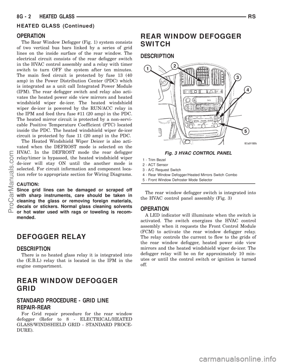
The rear window defogger switch is integrated into
the HVAC control panel assembly (Fig. 3)
OPERATION
A LED indicator will illuminate when the switch is
activated. The switch energizes the HVAC control
assembly when it requests the Front Control Module
(FCM) to activate the rear window defogger relay.
The relay controls the current to flow to the grids of
the rear window defogger, heated power side view
mirrors and the heated windshield wiper de-icer. The
defogger relay will be on for approximately 10 min-
utes or until the control switch or ignition is turned
off.
Fig. 3 HVAC CONTROL PANEL
1 - Trim Bezel
2 - ACT Sensor
3 - A/C Request Switch
4 - Rear Window Defogger/Heated Mirrors Switch Combo
5 - Front Window Defroster Mode Selector
8G - 2 HEATED GLASSRS
HEATED GLASS (Continued)
ProCarManuals.com
Page 434 of 2321
HEATED MIRRORS
TABLE OF CONTENTS
page page
HEATED MIRRORS
DESCRIPTION............................5
OPERATION.............................5
DIAGNOSIS AND TESTING..................5
HEATED MIRROR TEST...................5
MIRROR SWITCH
DESCRIPTION............................5OPERATION.............................5
HEATED MIRROR GRID
STANDARD PROCEDURE...................6
HEATED MIRROR.......................6
RELAY
DESCRIPTION............................6
HEATED MIRRORS
DESCRIPTION
Heated mirrors are available on models with
Power Mirrors and Rear Window Defogger only.
OPERATION
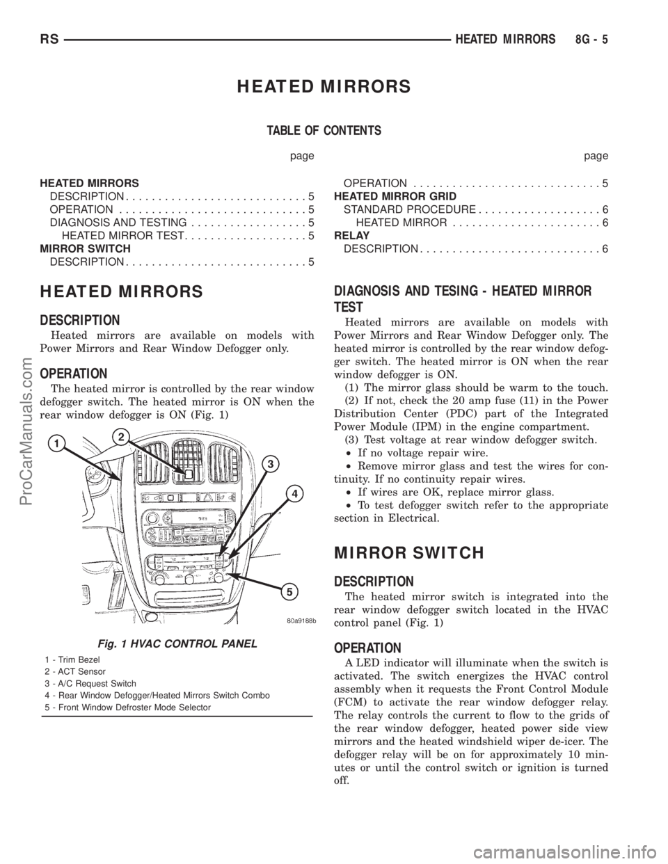
The heated mirror is controlled by the rear window
defogger switch. The heated mirror is ON when the
rear window defogger is ON (Fig. 1)
DIAGNOSIS AND TESING - HEATED MIRROR
TEST
Heated mirrors are available on models with
Power Mirrors and Rear Window Defogger only. The
heated mirror is controlled by the rear window defog-
ger switch. The heated mirror is ON when the rear
window defogger is ON.
(1) The mirror glass should be warm to the touch.
(2) If not, check the 20 amp fuse (11) in the Power
Distribution Center (PDC) part of the Integrated
Power Module (IPM) in the engine compartment.
(3) Test voltage at rear window defogger switch.
²If no voltage repair wire.
²Remove mirror glass and test the wires for con-
tinuity. If no continuity repair wires.
²If wires are OK, replace mirror glass.
²To test defogger switch refer to the appropriate
section in Electrical.
MIRROR SWITCH
DESCRIPTION
The heated mirror switch is integrated into the
rear window defogger switch located in the HVAC
control panel (Fig. 1)
OPERATION
A LED indicator will illuminate when the switch is
activated. The switch energizes the HVAC control
assembly when it requests the Front Control Module
(FCM) to activate the rear window defogger relay.
The relay controls the current to flow to the grids of
the rear window defogger, heated power side view
mirrors and the heated windshield wiper de-icer. The
defogger relay will be on for approximately 10 min-
utes or until the control switch or ignition is turned
off.
Fig. 1 HVAC CONTROL PANEL
1 - Trim Bezel
2 - ACT Sensor
3 - A/C Request Switch
4 - Rear Window Defogger/Heated Mirrors Switch Combo
5 - Front Window Defroster Mode Selector
RSHEATED MIRRORS8G-5
ProCarManuals.com
Page 558 of 2321
POWER MIRRORS
TABLE OF CONTENTS
page page
POWER MIRRORS
DESCRIPTION...........................45
OPERATION.............................45
DIAGNOSIS AND TESTING.................45
POWER MIRRORS......................45
AUTOMATIC DAY / NIGHT MIRROR
DESCRIPTION...........................46
OPERATION.............................46
DIAGNOSIS AND TESTING.................47AUTOMATIC DAY/NIGHT MIRROR..........47
REMOTE SWITCH
DIAGNOSIS AND TESTING.................48
REMOTE SWITCH......................48
REMOVAL..............................48
INSTALLATION...........................48
SIDEVIEW MIRROR
REMOVAL..............................48
POWER MIRRORS
DESCRIPTION
If equipped with power mirrors, the control switch
is located on the instrument panel to the left of the
headlamp switch.
OPERATION
The power mirrors are connected to battery feed at
all times. Each mirror head contains two electric
motors, two drive mechanisms, an electric heating
element, and the mirror glass. If the vehicle is
equipped with the optional memory system, each
mirror head also contains both a horizontal and a
vertical motor position sensor. One motor and drive
controls mirror up-and-down movement, and the
other controls right-and-left movement.
An optional driver side outside electrochromic mir-
ror is able to automatically change its reflectance
level. This mirror is controlled by the circuitry of the
automatic day/night inside rear view mirror. A thin
layer of electrochromic material between two pieces
of conductive glass make up the face of the mirror.
Two photocell sensors on the inside rear view mirror
are used to monitor light levels and adjust the reflec-tance of both the inside and driver side outside mir-
rors. This change in reflectance helps to reduce the
glare of headlamps approaching the vehicle from the
rear. (Refer to 8 - ELECTRICAL/POWER MIRRORS/
AUTOMATIC DAY / NIGHT MIRROR - DESCRIP-
TION) for more information on this system.
The motors which operate the mirrors are part of
the mirror assembly and cannot be serviced sepa-
rately.
DIAGNOSIS AND TESTING - POWER MIRRORS
(1) Remove Power Mirror Switch. (Refer to 8 -
ELECTRICAL/POWER MIRRORS/POWER MIRROR
SWITCH - REMOVAL).
(2) Disconnect wiring harness connector to the
power mirror switch and headlamp switch.
(3) Using two jumper wires:
²Connect one to a 12-volt source
²Connect the other to a good body ground
²Refer to the Mirror Test Chart for wire hookups
at the switch connector (Fig. 1).
(4) If results shown in table are not obtained,
check for broken or shorted circuit, or replace mirror
assembly as necessary.
RSPOWER MIRRORS8N-45
ProCarManuals.com
Page 578 of 2321
POWER SYSTEMS
TABLE OF CONTENTS
page page
POWER FOLDAWAY MIRROR SWITCH
DESCRIPTION............................1
OPERATION.............................1REMOVAL...............................1
INSTALLATION............................2
POWER FOLDAWAY MIRROR
SWITCH
DESCRIPTION
These vehicles may be equipped with Power Fold-
away Mirrors. This feature allows both the driver
and passenger side view mirrors to fold inward
(retract) on demand. The vehicle has an additional
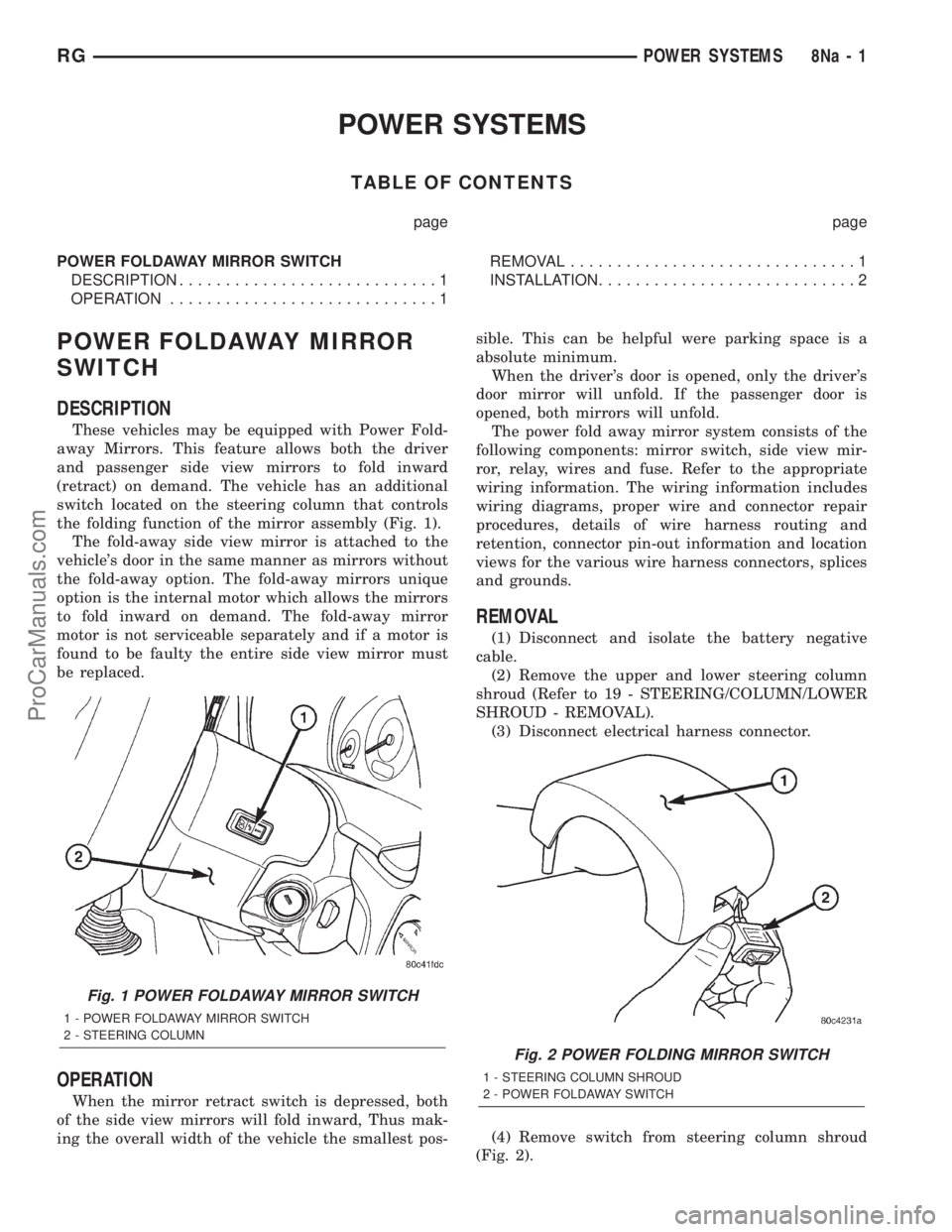
switch located on the steering column that controls
the folding function of the mirror assembly (Fig. 1).
The fold-away side view mirror is attached to the
vehicle's door in the same manner as mirrors without
the fold-away option. The fold-away mirrors unique
option is the internal motor which allows the mirrors
to fold inward on demand. The fold-away mirror
motor is not serviceable separately and if a motor is
found to be faulty the entire side view mirror must
be replaced.
OPERATION
When the mirror retract switch is depressed, both
of the side view mirrors will fold inward, Thus mak-
ing the overall width of the vehicle the smallest pos-sible. This can be helpful were parking space is a
absolute minimum.
When the driver's door is opened, only the driver's
door mirror will unfold. If the passenger door is
opened, both mirrors will unfold.
The power fold away mirror system consists of the
following components: mirror switch, side view mir-
ror, relay, wires and fuse. Refer to the appropriate
wiring information. The wiring information includes
wiring diagrams, proper wire and connector repair
procedures, details of wire harness routing and
retention, connector pin-out information and location
views for the various wire harness connectors, splices
and grounds.
REMOVAL
(1) Disconnect and isolate the battery negative
cable.
(2) Remove the upper and lower steering column
shroud (Refer to 19 - STEERING/COLUMN/LOWER
SHROUD - REMOVAL).
(3) Disconnect electrical harness connector.
(4) Remove switch from steering column shroud
(Fig. 2).
Fig. 1 POWER FOLDAWAY MIRROR SWITCH
1 - POWER FOLDAWAY MIRROR SWITCH
2 - STEERING COLUMN
Fig. 2 POWER FOLDING MIRROR SWITCH
1 - STEERING COLUMN SHROUD
2 - POWER FOLDAWAY SWITCH
RGPOWER SYSTEMS8Na-1
ProCarManuals.com
Page 2167 of 2321
cloudy days and at night it will probably be slightly
warmer. Infrared Three-Zone Temperature Control
provides side-to-side and front-to-rear variation in
comfort temperature settings. The Infrared Three-
Zone Automatic Temperature Control fan provides a
continuously variable air flow rate to meet occupant
comfort requirements.
FRONT CONTROL PANEL
²AUTO HI/LO± This system features two sets of
automatic control logic that allow either a rapid cool-
down rate or a somewhat slower cool-down rate with
less fan noise. HI-AUTO controls the system to reach
its assigned temperature quickly with a higher fan
speed. LO-AUTO controls the system to reach its
assigned temperature somewhat slower with less fan
noise. Both modes will automatically engage auto
recirculation.
²DE-FROST± The front de-frost function is
active when the rear window defogger function is
active or when the defog/defrost mode is selected.
²RECIRC± The RECIRC button will close the
air inlet door. If the system is in auto recirc (indica-
tor being displayed automatically), pressing the man-
ual recirc button will disable the auto recirc function
until one of the auto keys are pressed or the ignition
is cycled. If Auto HI/LO is pressed while manual
recirc is active, manual recirc will be deactivated.
²REAR WINDOW DEFOGGER± Pushing the
button sends a PCI bus message to the Intelligent
Power Module which controls the Rear Window
Defogger and side view mirror (if equipped) circuitry.
The defogger function will be active for 10 minutes
and can be turned off by a switch press. The defogger
will function while the control is in the OFF mode.
²FAN/MODE± The Fan and Mode knobs have
17 manual selectable positions. Manually changing
either of the rotary knobs for mode or fan speed set-
tings makes control of that function alone manual for
as long as the ignition is on. If only one is changed
manually, the other remains under automatic control.
Pressing the HI-AUTO/LO-AUTO rocker switch
restores full automatic control.
²REAR CONTROL± When the Rear System
control knob is moved to the OFF position, there will
be a delay of approximately 1 second before the sys-
tem actually turns off. This delay is to prevent an
undesired blower dropout if the knob is moved
through OFF to the other selections.
²BLOWER DELAY TIMER± The word DELAY
is displayed at start-up to signify that the system is
waiting so that cold air will not be blowing. This tells
the operator that it is unnecessary to turn the sys-
tem off, raise the temperature setting or turn the fan
speed setting down to prevent cold air from blowing.
A countdown in minutes and seconds until the engineis warm enough to begin delivering heat to the pas-
sengers alternates with the DELAY message at 25
second intervals. This countdown is based on actual
measurement of the rate of engine coolant tempera-
ture change. During the delay time, Defrost mode is
selected and the fan operates at a low speed to keep
the windshield fog free.
REAR CONTROL PANEL
Primary control of the rear compartment unit is in
the instrument panel center stack. The rear unit con-
trol knob there allows the driver to turn the rear
unit off, allow control by the intermediate seat occu-
pants by switching to the REAR position, or provide
fully automatic control based on the temperature set-
ting shown on the front control display.
²REAR CONTROL± Selecting automatic control
of the rear unit at the instrument panel, illuminates
a Locked Padlock in the rear control panel display.
Selecting REAR activates the rear control panel and
the Padlock then appears unlocked.
²FAN KNOB± The rear fan control has Off and
AUTO positions and a range of manual speed set-
tings that override the AUTO setting.
²MODE KNOB± The mode control allows inter-
mediate seat occupants to manually override the
automatic mode and select any balance of air flow
between overhead and floor outlets from full over-
head to full floor.
²SET TEMP± The rear set temp control will
operate identical to the front controls. If the front
control rear set temp button is pressed simulta-
neously with the rear control head, then the front
control head press events shall have priority, i.e. if
the front user presses Rear Set Temp down and the
rear user presses Set Temp up, then the rear set
temp will decrease.
DIAGNOSIS AND TESTING - A/C COOL DOWN
TEST
The heater-A/C control module can perform an A/C
cool down test, which is a test performed during the
manufacturing process to confirm that the air condi-
tioning system is performing satisfactorily. This test
can also provide a quick confirmation of air condi-
tioning system performance to the service technician.
If the test is completed satisfactorily, no further ser-
vice is required. If the test is failed, proceed to the
A/C Performance Test to confirm the a/c system is
operating properly, or use a DRBIIItscan tool to
diagnose the A/C system control and distribution sys-
tems. Refer to the appropriate diagnostic informa-
tion.
24 - 4 HEATING & AIR CONDITIONINGRS
HEATING & AIR CONDITIONING (Continued)
ProCarManuals.com