remote start DODGE TOWN AND COUNTRY 2001 Service Manual
[x] Cancel search | Manufacturer: DODGE, Model Year: 2001, Model line: TOWN AND COUNTRY, Model: DODGE TOWN AND COUNTRY 2001Pages: 2321, PDF Size: 68.09 MB
Page 415 of 2321
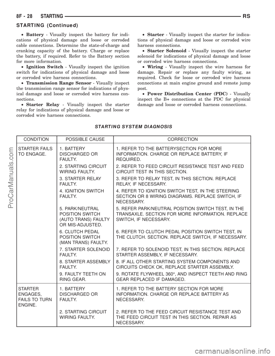
²Battery- Visually inspect the battery for indi-
cations of physical damage and loose or corroded
cable connections. Determine the state-of-charge and
cranking capacity of the battery. Charge or replace
the battery, if required. Refer to the Battery section
for more information.
²Ignition Switch- Visually inspect the ignition
switch for indications of physical damage and loose
or corroded wire harness connections.
²Transmission Range Sensor- Visually inspect
the transmission range sensor for indications of phys-
ical damage and loose or corroded wire harness con-
nections.
²Starter Relay- Visually inspect the starter
relay for indications of physical damage and loose or
corroded wire harness connections.²Starter- Visually inspect the starter for indica-
tions of physical damage and loose or corroded wire
harness connections.
²Starter Solenoid- Visually inspect the starter
solenoid for indications of physical damage and loose
or corroded wire harness connections.
²Wiring- Visually inspect the wire harness for
damage. Repair or replace any faulty wiring, as
required. Check for loose or corroded wire harness
connections at main engine ground and remote jump
post.
²Power Distribution Center (PDC)- Visually
inspect the B+ connections at the PDC for physical
damage and loose or corroded harness connections.
STARTING SYSTEM DIAGNOSIS
CONDITION POSSIBLE CAUSE CORRECTION
STARTER FAILS
TO ENGAGE.1. BATTERY
DISCHARGED OR
FAULTY.1. REFER TO THE BATTERYSECTION FOR MORE
INFORMATION. CHARGE OR REPLACE BATTERY, IF
REQUIRED.
2. STARTING CIRCUIT
WIRING FAULTY.2. REFER TO FEED CIRCUIT RESISTANCE TEST AND FEED
CIRCUIT TEST IN THIS SECTION.
3. STARTER RELAY
FAULTY.3. REFER TO RELAY TEST, IN THIS SECTION. REPLACE
RELAY, IF NECESSARY.
4. IGNITION SWITCH
FAULTY.4. REFER TO IGNITION SWITCH TEST, IN THE STEERING
SECTION OR 8 WIRING DIAGRAMS. REPLACE SWITCH, IF
NECESSARY.
5. PARK/NEUTRAL
POSITION SWITCH
(AUTO TRANS) FAULTY
OR MIS-ADJUSTED.5. REFER PARK/NEUTRAL POSITION SWITCH TEST, IN THE
TRANSAXLE. SECTION FOR MORE INFORMATION. REPLACE
SWITCH, IF NECESSARY.
6. CLUTCH PEDAL
POSITION SWITCH
(MAN TRANS) FAULTY.6. REFER TO CLUTCH PEDAL POSITION SWITCH TEST, IN
THE CLUTCH. SECTION. REPLACE SWITCH, IF NECESSARY.
7. STARTER SOLENOID
FAULTY.7. REFER TO SOLENOID TEST, IN THIS SECTION. REPLACE
STARTER ASSEMBLY, IF NECESSARY.
8. STARTER ASSEMBLY
FAULTY.8. IF ALL OTHER STARTING SYSTEM COMPONENTS AND
CIRCUITS CHECK OK, REPLACE STARTER ASSEMBLY.
9. FAULTY TEETH ON
RING GEAR.9. ROTATE FLYWHEEL 360É, AND INSPECT TEETH AND RING
GEAR REPLACED IF DAMAGED.
STARTER
ENGAGES,
FAILS TO TURN
ENGINE.1. BATTERY
DISCHARGED OR
FAULTY.1. REFER TO THE BATTERY SECTION FOR MORE
INFORMATION. CHARGE OR REPLACE BATTERY AS
NECESSARY.
2. STARTING CIRCUIT
WIRING FAULTY.2. REFER TO THE FEED CIRCUIT RESISTANCE TEST AND
THE FEED CIRCUIT TEST IN THIS SECTION. REPAIR AS
NECESSARY.
8F - 28 STARTINGRS
STARTING (Continued)
ProCarManuals.com
Page 417 of 2321
(5) Connect a remote starter switch or a jumper
wire between the remote battery positive post and
terminal 87 of the starter relay connector.
(a) If engine cranks, starter/starter solenoid is
good. Go to the Starter Relay Test.
(b) If engine does not crank or solenoid chatters,
check wiring and connectors from starter relay to
starter solenoid for loose or corroded connections.
Particularly at starter terminals.
(c) Repeat test. If engine still fails to crank prop-
erly, trouble is within starter or starter mounted
solenoid, and replace starter.
STARTER RELAY
WARNING: CHECK TO ENSURE THAT THE TRANS-
MISSION IS IN THE PARK/NEUTRAL POSITION
WITH THE PARKING BRAKE APPLIED.
RELAY TEST
The starter relay is located in the Power Distribu-
tion Center (PDC) in the engine compartment. Refer
to the PDC label for relay identification and location.
Remove the starter relay from the PDC as
described in this group to perform the following tests:
(1) A relay in the de-energized position should
have continuity between terminals 87A and 30, and
no continuity between terminals 87 and 30. If OK, go
to Step 2. If not OK, replace the faulty relay.
(2) Resistance between terminals 85 and 86 (elec-
tromagnet) should be 7565 ohms. If OK, go to Step
3. If not OK, replace the faulty relay.
(3) Connect a battery B+ lead to terminals 86 and
a ground lead to terminal 85 to energize the relay.
The relay should click. Also test for continuity
between terminals 30 and 87, and no continuity
between terminals 87A and 30. If OK, refer to Relay
Circuit Test procedure. If not OK, replace the faulty
relay.
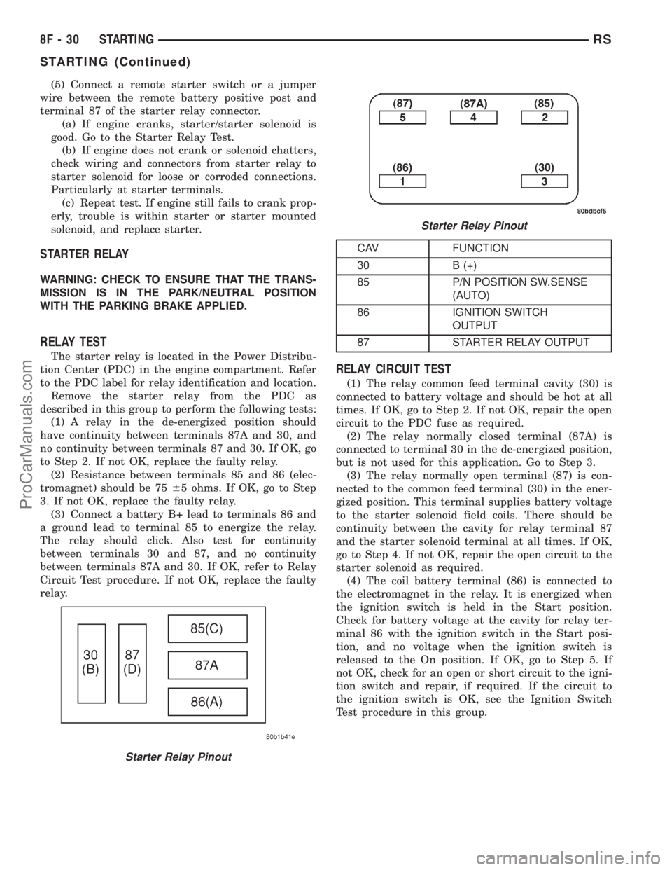
CAV FUNCTION
30 B (+)
85 P/N POSITION SW.SENSE
(AUTO)
86 IGNITION SWITCH
OUTPUT
87 STARTER RELAY OUTPUT
RELAY CIRCUIT TEST
(1) The relay common feed terminal cavity (30) is
connected to battery voltage and should be hot at all
times. If OK, go to Step 2. If not OK, repair the open
circuit to the PDC fuse as required.
(2) The relay normally closed terminal (87A) is
connected to terminal 30 in the de-energized position,
but is not used for this application. Go to Step 3.
(3) The relay normally open terminal (87) is con-
nected to the common feed terminal (30) in the ener-
gized position. This terminal supplies battery voltage
to the starter solenoid field coils. There should be
continuity between the cavity for relay terminal 87
and the starter solenoid terminal at all times. If OK,
go to Step 4. If not OK, repair the open circuit to the
starter solenoid as required.
(4) The coil battery terminal (86) is connected to
the electromagnet in the relay. It is energized when
the ignition switch is held in the Start position.
Check for battery voltage at the cavity for relay ter-
minal 86 with the ignition switch in the Start posi-
tion, and no voltage when the ignition switch is
released to the On position. If OK, go to Step 5. If
not OK, check for an open or short circuit to the igni-
tion switch and repair, if required. If the circuit to
the ignition switch is OK, see the Ignition Switch
Test procedure in this group.
Starter Relay Pinout
Starter Relay Pinout
8F - 30 STARTINGRS
STARTING (Continued)
ProCarManuals.com
Page 556 of 2321
REMOTE KEYLESS ENTRY
MODULE
DESCRIPTION
The RKE module is capable of retaining up to four
different Vehicle Access Codes.
OPERATION
Whenever the vehicle battery power is interrupted
the RKE Module will retain all vehicle access codes
in its memory. When replacing or adding a key fob
transmitter (maximum 4) a DRB IIItscan tool is
required to program the RKE Module to accept the
new Vehicle Access Code if a customer owned trans-
mitter is not available. Refer to Electrical, Remote
Keyless Entry Module, Standard Procedure - Pro-
gramming RKE Module or the Proper Body Diagnos-
tic Procedures manual.
DIAGNOSIS AND TESTING - REMOTE KEYLESS
ENTRY
Refer to the appropriate wiring information. The
wiring information includes wiring diagrams, proper
wire and connector repair procedures, further details
on wire harness routing and retention, as well as
pin-out and location views for the various wire har-
ness connectors, splices and grounds. Refer to the
proper Body Diagnostic Procedures Manual for test-
ing the Remote Keyless Entry system using a DRB
IIItscan tool. Also refer to other interrelated sys-
tems groups within this manual:
²Vehicle Theft Security System
²Power Seats
²Power Mirrors
STANDARD PROCEDURE - PROGRAMMING
RKE MODULE
(1) Using a functional key fob transmitter, unlock
the vehicle and disarm the Vehicle Theft Security
System.
(2) Insert ignition key into the ignition switch.
(3) Turn the ignition switch to RUN position with-
out starting engine.
(4) Using a functional key fob transmitter, press
and hold the UNLOCK button for a minimum five
seconds (maximum ten seconds).
(5) While still holding UNLOCK button, and
before ten seconds passes, press the PANIC button
and release both at the same time. A single chime
will sound to verify that the RKE module is set to
receive the new Vehicle Access Code(s).
(6) Within 30 seconds of the chime, press and
release the ªLOCKº and ªUNLOCKº buttons on the
transmitter at the same time. Then press any one of
the buttons. The BCM will sound an abbreviatedchime to acknowledge that the programming of the
transmitter has been completed and was successful.
(7) Repeat step 6 for all transmitters that will be
used with this vehicle (up to 4 total).
(8) Programming mode will last for 30 seconds. To
get out of programming mode sooner, turn the igni-
tion OFF. A single chime will sound to verify that the
RKE module will no longer accept additional Vehicle
Access Code(s).
(9) When Vehicle Access Code(s) programming is
complete, turn the ignition switch to the OFF posi-
tion and verify RKE system operation using each key
fob.
NOTE:
Only the two key fob transmitters that have been
programmed to the memory seat and mirror system
will operate it. If any key fob is replaced, the mem-
ory seat and mirror module will require program-
ming. (Refer to 8 - ELECTRICAL/POWER SEATS -
DIAGNOSIS AND TESTING).
REMOVAL
(1) Disconnect and isolate the battery negative
cable.
(2) Remove instrument panel top cover (Refer to
23 - BODY/INSTRUMENT PANEL/INSTRUMENT
PANEL TOP PAD - REMOVAL).
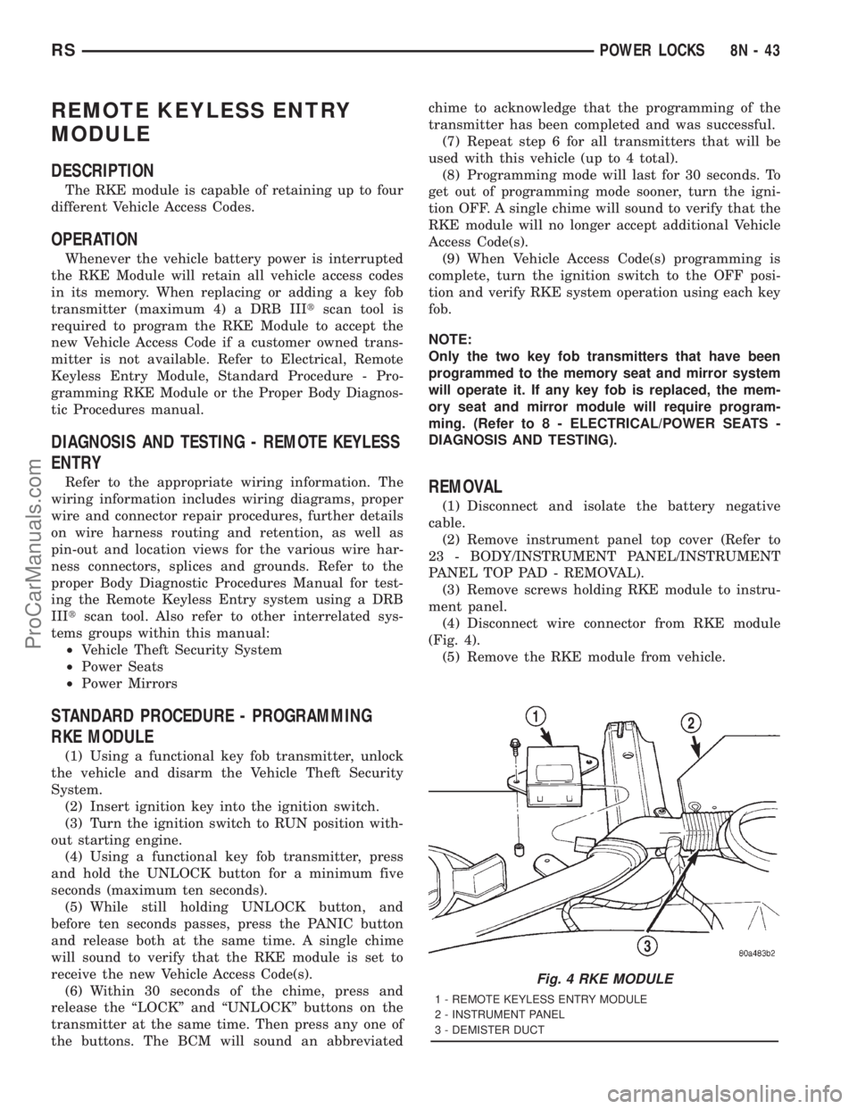
(3) Remove screws holding RKE module to instru-
ment panel.
(4) Disconnect wire connector from RKE module
(Fig. 4).
(5) Remove the RKE module from vehicle.
Fig. 4 RKE MODULE
1 - REMOTE KEYLESS ENTRY MODULE
2 - INSTRUMENT PANEL
3 - DEMISTER DUCT
RSPOWER LOCKS8N-43
ProCarManuals.com
Page 602 of 2321
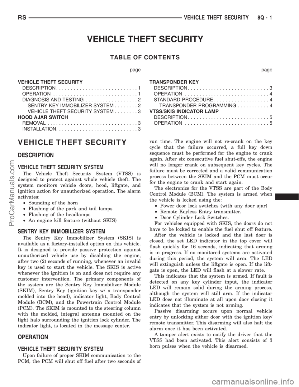
VEHICLE THEFT SECURITY
TABLE OF CONTENTS
page page
VEHICLE THEFT SECURITY
DESCRIPTION............................1
OPERATION.............................1
DIAGNOSIS AND TESTING..................2
SENTRY KEY IMMOBILIZER SYSTEM........2
VEHICLE THEFT SECURITY SYSTEM........3
HOOD AJAR SWITCH
REMOVAL...............................3
INSTALLATION............................3TRANSPONDER KEY
DESCRIPTION............................3
OPERATION.............................4
STANDARD PROCEDURE...................4
TRANSPONDER PROGRAMMING...........4
VTSS/SKIS INDICATOR LAMP
DESCRIPTION............................5
OPERATION.............................5
VEHICLE THEFT SECURITY
DESCRIPTION
VEHICLE THEFT SECURITY SYSTEM
The Vehicle Theft Security System (VTSS) is
designed to protect against whole vehicle theft. The
system monitors vehicle doors, hood, liftgate, and
ignition action for unauthorized operation. The alarm
activates:
²Sounding of the horn
²Flashing of the park and tail lamps
²Flashing of the headlamps
²An engine kill feature (without SKIS)
SENTRY KEY IMMOBILIZER SYSTEM
The Sentry Key Immobilizer System (SKIS) is
available as a factory-installed option on this vehicle.
It is designed to provide passive protection against
unauthorized vehicle use by disabling the engine,
after two (2) seconds of running, whenever an invalid
key is used to start the vehicle. The SKIS is active
whenever the ignition is on and does not require any
customer intervention. The primary components of
the system are the Sentry Key Immobilizer Module
(SKIM), Sentry Key (ignition key w/ a transponder
molded into the head), indicator light, Body Control
Module (BCM), and the Powertrain Control Module
(PCM). The SKIM is mounted to the steering column
with the molded, integral antenna mounted on the
light halo surrounding the ignition lock cylinder. The
indicator light, is located in the message center.
OPERATION
VEHICLE THEFT SECURITY SYSTEM
Upon failure of proper SKIM communication to the
PCM, the PCM will shut off fuel after two seconds ofrun time. The engine will not re-crank on the key
cycle that the failure occurred, a full key down
sequence must be performed for the engine to crank
again. After six consecutive fuel shut-offs, the engine
will no longer crank on subsequent key cycles. The
failure must be corrected and a valid communication
process between the SKIM and the PCM must occur
for the engine to crank and start again.
The electronics for the VTSS are part of the Body
Control Module (BCM). The system is armed when
the vehicle is locked using the:
²Power door lock switches (with any door ajar)
²Remote Keyless Entry transmitter.
²Door Cylinder Lock Switches.
For vehicles equipped with SKIS, the doors do not
have to be locked to enable the fuel shut off feature.
After the vehicle is locked and the last door is
closed, the set LED indicator in the top cover will
flash quickly for 16 seconds, indicating that arming
is in progress. If no monitored systems are activated
during this period, the system will arm. The LED
will extinguish unless the liftgate is open. If the lift-
gate is open, the LED will flash at a slower rate.
This indicates that the system is armed. If fault is
detected on any key cylinder input, the indicator
LED will remain solid during the arming process,
although the system will still arm. If the indicator
LED does not illuminate at all upon door closing it
indicates that the system is not arming.
Passive disarming occurs upon normal vehicle
entry by unlocking either door with the ignition key/
remote transmitter. This disarming will also halt the
alarm once it has been activated.
A tamper alert exists to notify the driver that the
VTSS had been activated. This alert consists of 3
horn pulses when the vehicle is disarmed.
RSVEHICLE THEFT SECURITY8Q-1
ProCarManuals.com
Page 604 of 2321
NOTE: The following tests may not prove conclu-
sive in the diagnosis of this system. The most reli-
able, efficient, and accurate means to diagnose the
Sentry Key Immobilizer System involves the use of
a DRB IIITscan tool. Refer to the proper Body Diag-
nostic Procedures Manual.
The Sentry Key Immobilizer System (SKIS) and
the Programmable Communication Interface (PCI)
bus network should be diagnosed using a DRB IIIt
scan tool. The DRB IIItwill allow confirmation that
the PCI bus is functional, that the Sentry Key Immo-
bilizer Module (SKIM) is placing the proper messages
on the PCI bus, and that the Powertrain Control
Module (PCM) is receiving the PCI bus messages.
Refer to the proper Body Diagnostic Procedures man-
ual, and Wiring Diagrams for complete circuit
descriptions and diagrams.
(1) Check the fuses in the Integrated Power Mod-
ule (IPM). If OK, go to Step 2. If not OK, repair the
shorted circuit or component as required and replace
the faulty fuse.
(2) Disconnect and isolate the battery negative
remote cable from the remote terminal. Unplug the
wire harness connector at the SKIM. Check for con-
tinuity between the ground circuit cavity of the
SKIM wire harness connector and a good ground.
There should be continuity. If OK, go to Step 3. If not
OK, repair the open circuit to ground as required.
(3) Connect the battery negative cable. Check for
battery voltage at the fused B(+) circuit cavity of the
SKIM wire harness connector. If OK, go to Step 4. If
not OK, repair the open circuit to the fuse in the
IPM as required.
(4) Turn the ignition switch to the ON position.
Check for battery voltage at the fused ignition switch
output (run/start) circuit cavity of the SKIM wire
harness connector. If OK, use a DRB IIItscan tool
and the proper Body Diagnostic Procedures manual
to complete the diagnosis of the SKIS. If not OK,
repair the open circuit to the fuse in the IPM as
required.
DIAGNOSIS AND TESTING - VEHICLE THEFT
SECURITY SYSTEM
Refer to the appropriate wiring information. The
wiring information includes wiring diagrams, proper
wire and connector repair procedures, further details
on wire harness routing and retention, as well as
pin-out and location views for the various wire har-
ness connectors, splices and grounds. Using a DRB
IIItscan tool. Refer to the proper Body Diagnostic
Procedures Manual for test procedures.
HOOD AJAR SWITCH
REMOVAL
(1) Disconnect and isolate the battery negative
cable.
(2) Using a small flat blade screwdriver, pry trig-
ger switch from the bracket on the left fender well.
(3) Disconnect the hood ajar switch from the wire
connector and remove from vehicle.
INSTALLATION
(1) Connect the hood ajar switch to the wire conec-
tor.
(2) Press the hood ajar switch into position on the
bracket located on the left inner fender well.
(3) Reconnect the battery negative cable.
(4) Close the hood and check for proper operation.
TRANSPONDER KEY
DESCRIPTION
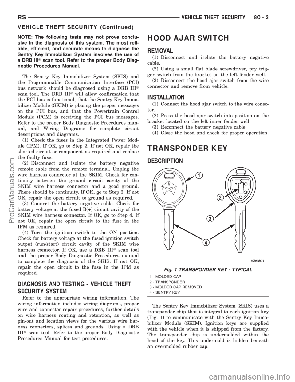
The Sentry Key Immobilizer System (SKIS) uses a
transponder chip that is integral to each ignition key
(Fig. 1) to communicate with the Sentry Key Immo-
bilizer Module (SKIM). Ignition keys are supplied
with the vehicle when it is shipped from the factory.
The transponder chip is undermolded within the
head of the key. This undermold is hidden beneath
an overmolded rubber cap.
Fig. 1 TRANSPONDER KEY - TYPICAL
1 - MOLDED CAP
2 - TRANSPONDER
3 - MOLDED CAP REMOVED
4 - SENTRY KEY
RSVEHICLE THEFT SECURITY8Q-3
VEHICLE THEFT SECURITY (Continued)
ProCarManuals.com
Page 633 of 2321
Component Page
Ignition Switch....................... 8Wa-10
Inlet Air Temperature Sensor............ 8Wa-30
Instrument Cluster................... 8Wa-40
Instrument Panel Switch Bank . . 8Wa-44, 52, 53, 63
Intelligent Power Module............... 8Wa-10
Knock Sensor........................ 8Wa-30
Leak Detection Pump.................. 8Wa-30
License Lamp........................ 8Wa-51
Lift Pump Motor..................... 8Wa-30
Lift Pump Relay...................... 8Wa-30
Liftgate Ajar Switch................... 8Wa-61
Liftgate Cinch/Release Motor............ 8Wa-61
Liftgate Cylinder Lock Switch........... 8Wa-39
Liftgate Flood Lamps.................. 8Wa-44
Liftgate Left Pinch Sensor.............. 8Wa-61
Low Beam Lamps.................... 8Wa-50
Manifold Absolute Pressure Sensor....... 8Wa-30
Mass Air Flow Sensor................. 8Wa-30
Memory Power Seat Switch............. 8Wa-63
Memory Seat Front Vertical Motor........ 8Wa-63
Memory Seat Front Vertical Position
Sensor........................... 8Wa-63
Memory Seat Horizontal Motor.......... 8Wa-63
Memory Seat Horizontal Position Sensor . . . 8Wa-63
Memory Seat Rear Vertical Motor........ 8Wa-63
Memory Seat Rear Vertical Position
Sensor........................... 8Wa-63
Memory Seat Recliner Motor............ 8Wa-63
Memory Seat Recliner Position Sensor..... 8Wa-63
Memory Seat Switch.................. 8Wa-63
Memory Seat/Mirror Module............ 8Wa-62
Message Center...................... 8Wa-46
Mode Door Actuator................... 8Wa-42
Multi- Function Switch................ 8Wa-50
Name Brand Speaker Relay............. 8Wa-47
Occupant Restraint Controller........... 8Wa-43
Overhead Console.................... 8Wa-49
Oxygen Sensors...................... 8Wa-30
Park Lamp Relay..................... 8Wa-10
Park Lamps......................... 8Wa-50
Park/Neutral Position Switch............ 8Wa-31
Park/Turn Signal Lamps............... 8Wa-50
Parking Brake Switch................. 8Wa-40
Passenger Folding Mirror Relay.......... 8Wa-62
Power Folding Mirror Switch............ 8Wa-62
Power Liftgate Motor.................. 8Wa-61
Power Mirror Switch.................. 8Wa-62
Power Mirrors....................... 8Wa-62
Power Outlets....................... 8Wa-41
Power Seat Circuit Breaker............. 8Wa-10
Power Seat Front Riser Motors.......... 8Wa-63
Power Seat Horizontal Motors........... 8Wa-63
Power Seat Rear Riser Motors........... 8Wa-63
Power Seat Recliner Motors............. 8Wa-63Component Page
Power Seat Switches.................. 8Wa-63
Power Window Circuit Breaker.......... 8Wa-10
Power Window Motors................. 8Wa-60
Power Window Switches................ 8Wa-60
Powertrain Control Module............. 8Wa-30
PTC ............................... 8Wa-10
Radiator Fan Relays.................. 8Wa-42
Radiator Fans....................... 8Wa-42
Radio Choke......................... 8Wa-47
Radio.............................. 8Wa-47
Reading Lamps...................... 8Wa-44
Rear A/C-Heater Unit................. 8Wa-42
Rear Auto Temp Control Switch.......... 8Wa-42
Rear Blower Front Control Switch........ 8Wa-42
Rear Blower Motor Power Module........ 8Wa-42
Rear Blower Motor Relay............... 8Wa-42
Rear Blower Motor.................... 8Wa-42
Rear Blower Rear Control Switch........ 8Wa-42
Rear Intrusion Sensor................. 8Wa-39
Rear Lamp Assemblies................. 8Wa-51
Rear Mode Motor..................... 8Wa-42
Rear Temperature Motor............... 8Wa-42
Rear Washer Pump Motor.............. 8Wa-53
Rear Window Defogger Grid............. 8Wa-48
Rear Wiper Motor.................... 8Wa-53
Recirculation Door Actuator............. 8Wa-42
Remote Keyless Entry Antenna.......... 8Wa-61
Remote Keyless Entry Module........... 8Wa-61
Remote Radio Switches................ 8Wa-47
Repeater Lamps...................... 8Wa-52
Seat Airbags......................... 8Wa-43
Seat Belt Switches.................... 8Wa-43
Seat Belt Tensioners.................. 8Wa-43
Sentry Key Immobilizer Module.......... 8Wa-39
Side Impact Airbag Control Module....... 8Wa-43
Siren.............................. 8Wa-39
Sliding Door Control Modules........... 8Wa-61
Sliding Door Latch Sensing Switches...... 8Wa-61
Sliding Door Lock Motor/Ajar Switches.... 8Wa-61
Sliding Door Lock Motors............... 8Wa-61
Sliding Door Motors................... 8Wa-61
Solenoid/Pressure Switch Assy........... 8Wa-31
Speakers........................... 8Wa-47
Speed Control Servo................... 8Wa-33
Speed Control Switches................ 8Wa-33
Speed Sensor- Input................... 8Wa-31
Speed Sensor- Output................. 8Wa-31
Splice Information.................... 8Wa-70
Starter Motor Relay................... 8Wa-21
Starter Motor........................ 8Wa-21
Stop/Turn Signal Relays................ 8Wa-54
Thatcham Alarm Indicator.............. 8Wa-39
Thatcham Alarm Module............... 8Wa-39
Throttle Position Sensor................ 8Wa-30
8Wa - 02 - 2 8W-02 COMPONENT INDEXRG
ProCarManuals.com
Page 636 of 2321
8W-10 POWER DISTRIBUTION
Component PageA/C Compressor Clutch..................8Wa-10-19, 20, 38, 40
A/C Compressor Clutch Relay.............8Wa-10-19, 20, 37, 38, 40
Accessory Relay.......................8Wa-10-15, 26, 57
Ambient Temp Sensor........................8Wa-10-54
Auto Shut Down Relay......................8Wa-10-19, 34
Auto Temp Control.........................8Wa-10-33
Back-Up Lamp Switch........................8Wa-10-58
Battery........................8Wa-10-12, 13, 14, 34, 40
Blower Motor Resistor......................8Wa-10-17, 31
Body Control Module......8Wa-10-21, 33, 38, 41, 42, 44, 46, 47, 48, 49, 61
Brake Fluid Level Switch......................8Wa-10-57
Brake Lamp Switch.....................8Wa-10-21, 44, 59
Brake Transmission Shift Interlock Solenoid.............8Wa-10-55
Cabin Heater Assist.....................8Wa-10-20, 36, 52
Camshaft Position Sensor......................8Wa-10-37
Center High Mounted Stop Lamp..................8Wa-10-59
Clockspring.............................8Wa-10-53
Clutch Pedal Interlock Switch Jumper........8Wa-10-16, 30, 46, 47, 53
Clutch Pedal Interlock Switch............8Wa-10-16, 30, 46, 47, 53
Controller Antilock Brake...........8Wa-10-16, 21, 30, 42, 48, 54, 59
Crank Case Ventilation Heater...................8Wa-10-41
Data Link Connector.......................8Wa-10-29, 61
Defogger Relay......................8Wa-10-17, 18, 32, 56
Diagnostic Junction Port.......................8Wa-10-54
Driver Door Lock Switch.....................8Wa-10-28, 29
Driver Heated Seat Module.....................8Wa-10-42
Driver Power Seat Switch......................8Wa-10-42
Driver Power Window Switch....................8Wa-10-29
ECM/PCM Relay.........................8Wa-10-20, 36
EGR Solenoid..........................8Wa-10-37, 39
Electric Wiper De-Icer........................8Wa-10-28
Engine Control Module........8Wa-10-16, 20, 30, 36, 37, 40, 41, 58, 59
Floor Console Lamp.........................8Wa-10-27
Floor Console Power Outlet...................8Wa-10-27, 29
Front Blower Module......................8Wa-10-17, 31
Front Blower Motor Relay................8Wa-10-16, 17, 31, 56
Front Cigar Lighter.......................8Wa-10-15, 27
Front Control Module . . . 8Wa-10-14, 15, 16, 17, 18, 19, 20, 21, 22, 23, 24, 25,
26, 29, 30, 31, 32, 38, 40, 45, 46, 47, 50, 51, 52, 53, 54. 55, 56, 57, 58, 59, 61
Front Fog Lamp Relay....................8Wa-10-14, 22, 56
Front Washer Pump Motor..................8Wa-10-15, 26, 61
Front Wiper Hi/Low Relay..................8Wa-10-15, 25, 57
Front Wiper On/Off Relay..................8Wa-10-15, 25, 52
Fuel Heater.............................8Wa-10-41
Fuel Heater Relay......................8Wa-10-20, 40, 57
Fuel Injector No. 1..........................8Wa-10-35
Fuel Injector No. 2..........................8Wa-10-35
Fuel Injector No. 3..........................8Wa-10-35
Fuel Injector No. 4..........................8Wa-10-35
Fuel Injector No. 5..........................8Wa-10-35
Fuel Injector No. 6..........................8Wa-10-35
Fuel Pressure Solenoid.......................8Wa-10-37
Fuel Pump Module........................8Wa-10-19, 38
Fuel Pump Relay.......................8Wa-10-19, 38, 57
Fuse 1 (IPM).........................8Wa-10-14, 15, 22
Fuse 2 (IPM) (Diesel).....................8Wa-10-14, 10-24
Fuse 2 (IPM) (Gas)......................8Wa-10-14, 10-23
Fuse 3 (IPM).........................8Wa-10-14, 23, 24
Fuse 4 (IPM).......................8Wa-10-14, 15, 16, 25
Fuse 5 (IPM)...........................8Wa-10-15, 26
Fuse 6 (IPM)...........................8Wa-10-15, 26
Fuse 8 (IPM)...........................8Wa-10-16, 29
Fuse 9 (IPM).........................8Wa-10-16, 17, 30
Fuse 10 (IPM)..........................8Wa-10-17, 31
Fuse 11 (IPM)..........................8Wa-10-15, 26
Fuse 12 (IPM)..........................8Wa-10-17, 31
Fuse 13 (IPM)..........................8Wa-10-18, 32
Fuse 14 (IPM)....................8Wa-10-18, 19, 20, 32, 52
Fuse 15 (IPM) (Diesel)......................8Wa-10-20, 36
Fuse 15 (IPM) (Gas).....................8Wa-10-18, 19, 34
Fuse 16 (IPM) (Diesel)......................8Wa-10-20, 36
Fuse 16 (IPM) (Gas).......................8Wa-10-19, 34
Fuse 17 (IPM) (Diesel)......................8Wa-10-20, 40
Fuse 17 (IPM) (Gas).......................8Wa-10-19, 38
Fuse 18 (IPM)....................8Wa-10-19, 20, 21, 38, 40
Fuse 19 (IPM)......................8Wa-10-19, 20, 21, 42
Fuse 20 (IPM)..........................8Wa-10-21, 42
Fuse 21 (IPM)..........................8Wa-10-21, 42
Fuse 22 (IPM)..........................8Wa-10-21, 42
Fuse 23 (IPM)........................8Wa-10-21, 46, 47
Fuse 24 (IPM)............................8Wa-10-21
Fuse 24 (IPM)............................8Wa-10-44
Fuse 26 (IPM)..........................8Wa-10-21, 44
Fuse 27 (IPM)..........................8Wa-10-21, 44
Fuse 28 (IPM)..........................8Wa-10-15, 26
Fuse 30 (IPM)..........................8Wa-10-21, 45
Fuse 31 (IPM)..........................8Wa-10-21, 45
Fuse 32 (IPM)..........................8Wa-10-21, 45
Fuse 33 (IPM)............................8Wa-10-15
Fuse 33 (IPM)............................8Wa-10-26
Fuselink.............................8Wa-10-12, 13
G100................................8Wa-10-48
G101...............................8Wa-10-34, 40
G103................................8Wa-10-61
G300................................8Wa-10-50
G300................................8Wa-10-51
Generator........................8Wa-10-12, 13, 35, 37
Glow Plug Relay.........................8Wa-10-12, 37
Headlamp Switch........................8Wa-10-24, 55Component PageHeadlamp Washer Pump Motor.................8Wa-10-21, 45
Headlamp Washer Relay...................8Wa-10-21, 45, 56
High Note Horn...........................8Wa-10-29
Horn Relay..........................8Wa-10-16, 29, 52
Ignition Coil.............................8Wa-10-35
Ignition Switch............8Wa-10-16, 21, 30, 38, 39, 41, 46, 47, 53
Instrument Cluster.......................8Wa-10-21, 44
Intelligent Power Module . . 8Wa-10-2, 10-3, 10-4, 10-12, 14, 15, 16, 17, 18, 19,
20, 21, 22, 23, 24, 25, 26, 27, 28, 29, 30, 31, 32, 33, 34, 35, 36, 37, 38, 39, 40,
41, 42, 44, 45, 46, 47, 48, 49, 50, 51, 52, 53, 54, 55, 56, 57, 58, 59, 61
Leak Detection Pump........................8Wa-10-39
Left B-Pillar Switch.........................8Wa-10-28
Left Combination Relay.......................8Wa-10-60
Left Fog Lamp..........................8Wa-10-14, 22
Left Front Park/ Turn Signal Lamp............8Wa-10-14, 23, 49, 58
Left Headlamp............................8Wa-10-50
Left Headlamp Leveling Motor................8Wa-10-24, 55, 58
Left High Beam Lamp........................8Wa-10-51
Left Low Beam Lamp........................8Wa-10-51
Left Park Lamp.........................8Wa-10-24, 58
Left Power Mirror..........................8Wa-10-32
Left Rear Lamp Assembly..............8Wa-10-23, 24, 58, 59, 60
Left Repeater Lamp.........................8Wa-10-44
Left Side Impact Airbag Control Module...............8Wa-10-55
Left Sliding Door Control Module..................8Wa-10-45
Left Stop/ Turn Signal Relay.....................8Wa-10-60
Left Turn Signal Lamp.......................8Wa-10-49
License Lamp........................8Wa-10-23, 24, 58
Lift Pump Motor.........................8Wa-10-20, 36
Lift Pump Relay.........................8Wa-10-20, 36
Low Note Horn...........................8Wa-10-29
Mass Air Flow Sensor........................8Wa-10-37
Memory Seat/ Mirror Module....................8Wa-10-42
Message Center...........................8Wa-10-44
Name Brand Speaker Relay.................8Wa-10-18, 32, 52
Occupant Restraint Controller..................8Wa-10-56, 61
Overhead Console..........................8Wa-10-33
Oxygen Sensor 1/1 Upstream....................8Wa-10-35
Oxygen Sensor 1/2 Downstream...................8Wa-10-35
Park Lamp Relay.....................8Wa-10-14, 23, 24, 52
Park/ Neutral Position Switch....................8Wa-10-58
Passenger Door Lock Switch...................8Wa-10-26, 28
Passenger Folding Mirror Relay.............8Wa-10-19, 20, 38, 40
Passenger Heated Seat Module...................8Wa-10-43
Passenger Power Seat Switch....................8Wa-10-43
Passenger Power Window Switch..................8Wa-10-26
Power Liftgate Module......................8Wa-10-21, 45
Power Mirror Switch...................8Wa-10-19, 20, 39, 40
Power Outlet............................8Wa-10-29
Power Seat Circuit Breaker...................8Wa-10-21, 42
Power Window Circuit Breaker.................8Wa-10-15, 26
Powertrain Control Module........8Wa-10-16, 19, 30, 34, 35, 38, 39, 48
PTC4 ..............................8Wa-10-18, 32
Ptc7.............................8Wa-10-15, 16, 29
Radiator Fan Relay.....................8Wa-10-21, 44, 48
Radiator Fan Relay No. 1....................8Wa-10-12, 37
Radiator Fan Relay No. 2....................8Wa-10-37, 44
Radiator Fan Relay No. 3....................8Wa-10-21, 37
Radio..............................8Wa-10-27, 33
Radio Choke...........................8Wa-10-18, 32
Rear A/C-Heater Unit......................8Wa-10-17, 31
Rear Blower Motor Power Module..................8Wa-10-31
Rear Blower Motor Relay.................8Wa-10-17, 18, 31, 56
Rear Power Outlet......................8Wa-10-15, 26, 27
Rear Washer Pump Motor..................8Wa-10-15, 26, 61
Rear Window Defogger Grid...................8Wa-10-18, 32
Rear Wiper Motor..........................8Wa-10-28
Remote Keyless Entry Module....................8Wa-10-33
Right B-Pillar Switch........................8Wa-10-28
Right Combination Relay......................8Wa-10-60
Right Fog Lamp.........................8Wa-10-14, 22
Right Front Park/ Turn Signal Lamp...........8Wa-10-14, 23, 49, 53
Right Headlamp...........................8Wa-10-50
Right Headlamp Leveling Motor...............8Wa-10-24, 53, 55
Right High Beam Lamp.......................8Wa-10-51
Right Low Beam Lamp.......................8Wa-10-51
Right Park Lamp........................8Wa-10-24, 53
Right Power Mirror.........................8Wa-10-32
Right Rear Lamp Assembly................8Wa-10-14, 23, 24, 59
Right Repeater Lamp........................8Wa-10-44
Right Side Impact Airbag Control Module..............8Wa-10-55
Right Sliding Door Control Module.................8Wa-10-45
Right Stop/ Turn Signal Relay....................8Wa-10-60
Right Turn Signal Lamp.......................8Wa-10-49
Sentry Key Immobilizer Module...........8Wa-10-33, 39, 41, 46, 47
Solenoid/ Pressure Switch Assy...................8Wa-10-34
Starter Motor.......................8Wa-10-12, 13, 16, 30
Starter Motor Relay...................8Wa-10-16, 30, 46, 47
Thatcham Alarm Module.................8Wa-10-39, 41, 47, 61
Torque Converter Clutch Solenoid..................8Wa-10-39
Trailer Tow Connector......................8Wa-10-23, 58
Transmission Control Module...........8Wa-10-16, 19, 30, 34, 54, 55
Transmission Control Relay...................8Wa-10-19, 34
Transmission Range Sensor.....................8Wa-10-58
TXV Solenoid............................8Wa-10-31
Vehicle Speed Sensor........................8Wa-10-36
Washer Fluid Level Switch.....................8Wa-10-53
Wiper Module........................8Wa-10-15, 25, 52
RG8W-10 POWER DISTRIBUTION8Wa-10-1
ProCarManuals.com
Page 1051 of 2321
LEFT REMOTE RADIO SWITCH - BLACK 2 WAY
CAV CIRCUIT FUNCTION
1 X20 20RD/BK RADIO CONTROL MUX
2 X920 20RD/DB RADIO CONTROL MUX RETURN
LEFT REPEATER LAMP (BUILT-UP-EXPORT) - GRAY 2 WAY
CAV CIRCUIT FUNCTION
1 A701 18BR/RD FUSED B(+)
2 L163 20WT/BR LEFT SIDE REPEATER LAMP FEED
LEFT SEAT AIRBAG - YELLOW 2 WAY
CAV CIRCUIT FUNCTION
1 R33 18WT/BK (BUILT-UP-EXPORT) LEFT SEAT SQUIB LINE 2
1 R31 18LG/OR (EXCEPT BUILT-UP-EX-
PORT)LEFT SEAT SQUIB LINE 1
2 R31 18DG/WT (BUILT-UP-EXPORT) LEFT SEAT SQUIB LINE 1
2 R33 18LG/WT (EXCEPT BUILT-UP-EX-
PORT)LEFT SEAT SQUIB LINE 2
LEFT SIDE IMPACT AIRBAG CONTROL MODULE - YELLOW/RED 7 WAY
CAV CIRCUIT FUNCTION
1 R31 18LG/OR LEFT SEAT SQUIB LINE 1
2 R33 18LG/WT LEFT SEAT SQUIB LINE 2
3- -
4 D25 20WT/VT PCI BUS
5 F214 18PK/LG FCM OUTPUT (RUN-START)
6 Z104 18BK/LG GROUND
7 Z104 18BK/LG GROUND
LEFT SLIDING DOOR CONTROL MODULE C1 (POWER SLIDING DOOR) - BLACK 8 WAY
CAV CIRCUIT FUNCTION
1 Q45 18OR/GY LEFT CINCH/RELEASE MOTOR CLUTCH DRIVER
2 Q67 16TN/BR LEFT SLIDING DOOR OPEN DRIVER
3 Q69 16TN/OR LEFT SLIDING DOOR CLOSE DRIVER
4- -
5 A113 14WT/RD FUSED B(+)
6- -
7- -
8 Z123 14BK/WT GROUND
8Wa - 80 - 78 8W-80 CONNECTOR PIN-OUTSRG
ProCarManuals.com
Page 1086 of 2321
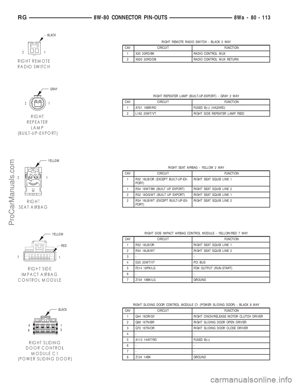
RIGHT REMOTE RADIO SWITCH - BLACK 2 WAY
CAV CIRCUIT FUNCTION
1 X20 20RD/BK RADIO CONTROL MUX
2 X920 20RD/DB RADIO CONTROL MUX RETURN
RIGHT REPEATER LAMP (BUILT-UP-EXPORT) - GRAY 2 WAY
CAV CIRCUIT FUNCTION
1 A701 18BR/RD FUSED B(+) (HAZARD)
2 L162 20WT/VT RIGHT SIDE REPEATER LAMP FEED
RIGHT SEAT AIRBAG - YELLOW 2 WAY
CAV CIRCUIT FUNCTION
1 R32 18LB/OR (EXCEPT BUILT-UP-EX-
PORT)RIGHT SEAT SQUIB LINE 1
1 R34 18WT/BK (BUILT UP EXPORT) RIGHT SEAT SQUIB LINE 2
2 R32 18DG/WT (BUILT UP EXPORT) RIGHT SEAT SQUIB LINE 1
2 R34 18LB/WT (EXCEPT BUILT-UP-EX-
PORT)RIGHT SEAT SQUIB LINE 2
RIGHT SIDE IMPACT AIRBAG CONTROL MODULE - YELLOW/RED 7 WAY
CAV CIRCUIT FUNCTION
1 R32 18LB/OR RIGHT SEAT SQUIB LINE 1
2 R34 18LB/WT RIGHT SEAT SQUIB LINE 2
3- -
4 D25 20WT/VT PCI BUS
5 F214 18PK/LG FCM OUTPUT (RUN-START)
6- -
7 Z104 18BK/LG GROUND
RIGHT SLIDING DOOR CONTROL MODULE C1 (POWER SLIDING DOOR) - BLACK 8 WAY
CAV CIRCUIT FUNCTION
1 Q44 18OR/GY RIGHT CINCH/RELEASE MOTOR CLUTCH DRIVER
2 Q68 16TN/BR RIGHT SLIDING DOOR OPEN DRIVER
3 Q70 16TN/OR RIGHT SLIDING DOOR CLOSE DRIVER
4- -
5 A113 14WT/RD FUSED B(+)
6- -
7- -
8 Z124 14BK GROUND
RG8W-80 CONNECTOR PIN-OUTS8Wa - 80 - 113
ProCarManuals.com
Page 1496 of 2321
(7) Install the splash shields below the engine
compartment.
(8) Lower the vehicle.
(9) Connect the negative (-) battery cable on the
negative battery post.
(10) Fill and bleed the power steering system
using the Power Steering Pump Initial Operation
Procedure (Refer to 19 - STEERING/PUMP - STAN-
DARD PROCEDURE).
(11) Inspect for leaks.
RESERVOIR
DESCRIPTION - RESERVOIR (2.5L DIESEL)
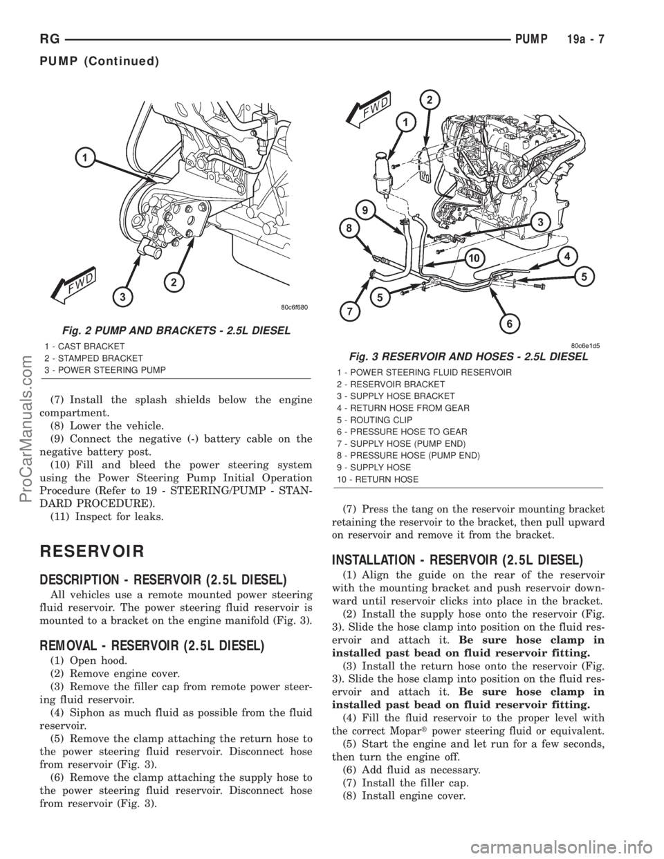
All vehicles use a remote mounted power steering
fluid reservoir. The power steering fluid reservoir is
mounted to a bracket on the engine manifold (Fig. 3).
REMOVAL - RESERVOIR (2.5L DIESEL)
(1) Open hood.
(2) Remove engine cover.
(3) Remove the filler cap from remote power steer-
ing fluid reservoir.
(4) Siphon as much fluid as possible from the fluid
reservoir.
(5) Remove the clamp attaching the return hose to
the power steering fluid reservoir. Disconnect hose
from reservoir (Fig. 3).
(6) Remove the clamp attaching the supply hose to
the power steering fluid reservoir. Disconnect hose
from reservoir (Fig. 3).(7)
Press the tang on the reservoir mounting bracket
retaining the reservoir to the bracket, then pull upward
on reservoir and remove it from the bracket.
INSTALLATION - RESERVOIR (2.5L DIESEL)
(1) Align the guide on the rear of the reservoir
with the mounting bracket and push reservoir down-
ward until reservoir clicks into place in the bracket.
(2) Install the supply hose onto the reservoir (Fig.
3). Slide the hose clamp into position on the fluid res-
ervoir and attach it.Be sure hose clamp in
installed past bead on fluid reservoir fitting.
(3) Install the return hose onto the reservoir (Fig.
3). Slide the hose clamp into position on the fluid res-
ervoir and attach it.Be sure hose clamp in
installed past bead on fluid reservoir fitting.
(4)
Fill the fluid reservoir to the proper level with
the correct Mopartpower steering fluid or equivalent.
(5) Start the engine and let run for a few seconds,
then turn the engine off.
(6) Add fluid as necessary.
(7) Install the filler cap.
(8) Install engine cover.
Fig. 2 PUMP AND BRACKETS - 2.5L DIESEL
1 - CAST BRACKET
2 - STAMPED BRACKET
3 - POWER STEERING PUMP
Fig. 3 RESERVOIR AND HOSES - 2.5L DIESEL
1 - POWER STEERING FLUID RESERVOIR
2 - RESERVOIR BRACKET
3 - SUPPLY HOSE BRACKET
4 - RETURN HOSE FROM GEAR
5 - ROUTING CLIP
6 - PRESSURE HOSE TO GEAR
7 - SUPPLY HOSE (PUMP END)
8 - PRESSURE HOSE (PUMP END)
9 - SUPPLY HOSE
10 - RETURN HOSE
RGPUMP19a-7
PUMP (Continued)
ProCarManuals.com