air DODGE TOWN AND COUNTRY 2003 Owner's Manual
[x] Cancel search | Manufacturer: DODGE, Model Year: 2003, Model line: TOWN AND COUNTRY, Model: DODGE TOWN AND COUNTRY 2003Pages: 2177, PDF Size: 59.81 MB
Page 39 of 2177
![DODGE TOWN AND COUNTRY 2003 Owners Manual Kilometers 156 000 160 000 168 000 180 000 192 000
(Miles) (97,500) (100,000) (105,000) (112,500) (120,000)
[Months] [78] [84] [90] [96]
Change engine oil and engine oil filter. X X X X
Inspect the br](/img/12/56918/w960_56918-38.png "DODGE TOWN AND COUNTRY 2003 Owners Manual Kilometers 156 000 160 000 168 000 180 000 192 000
(Miles) (97,500) (100,000) (105,000) (112,500) (120,000)
[Months] [78] [84] [90] [96]
Change engine oil and engine oil filter. X X X X
Inspect the br")
Kilometers 156 000 160 000 168 000 180 000 192 000
(Miles) (97,500) (100,000) (105,000) (112,500) (120,000)
[Months] [78] [84] [90] [96]
Change engine oil and engine oil filter. X X X X
Inspect the brake linings. X
Inspect the engine air cleaner filter, replace
if necessary. *XXXX
Replace theengine air cleaner filter.X
Replace thespark plugson 2.4 liter
engines.X
Replace theignition cableson 2.4 liter
engines.X
Inspect the tie rod ends and boot seals. X
Inspect and adjust the power steering pump
belt tension on 2.4 liter engines.XX
Inspect the generator belt on 2.4 liter
engines, replace if necessary.XX
Check and replace thePCV valve,if
necessary.*X
Inspect the serpentine drive belt on 3.3 liter
engines, replace if necessary. ³XX
Replace thespark plugs3.3 liter engines. X
Replace theignition cables3.3 liter
engines.X
Flush and replace the engine coolant at
100,000 miles, if not done at 60 months.X
Replace theengine timing belton 2.4 liter
engines only.X
Replace the air conditioning filter. X
* This maintenance is recommended by the manu-
facture to the owner but is not required to maintain
the emissions warranty.
³ This maintenance is not required if previously
replaced.
Inspection and service should also be performed
anytime a malfunction is observed or suspected.
Retain all receipts.WARNING: You can be badly injured working on or
around a motor vehicle. Do only that service work
for which you have the knowledge and the right
equipment. If you have any doubt about your ability
to perform a service job, take your vehicle to a
competent mechanic.
0a - 8 MAINTENANCE SCHEDULESRS
MAINTENANCE SCHEDULES FOR ALL MARKETS EXCEPT U.S., CANADA and MEXICO (Continued)
ProCarManuals.com
Page 41 of 2177
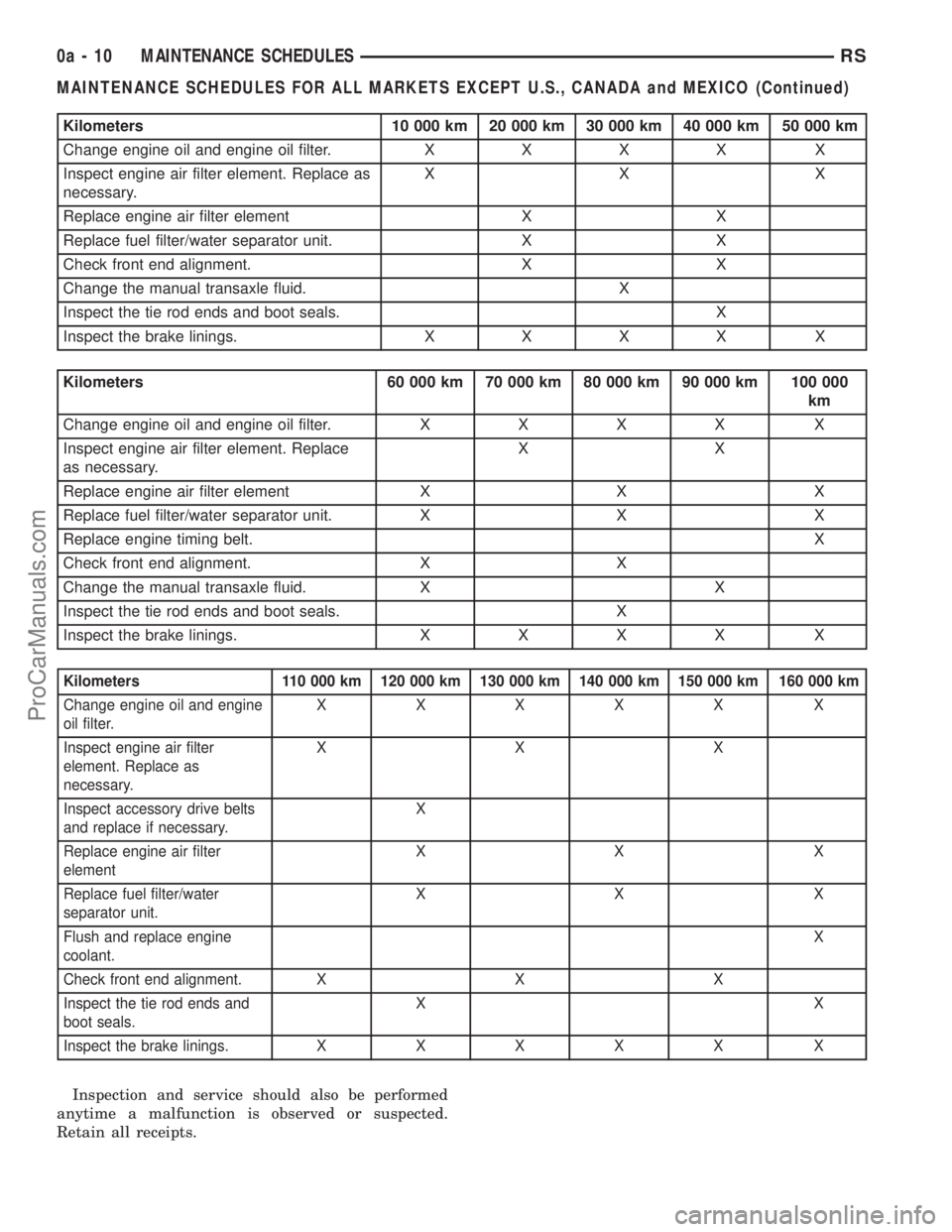
Kilometers 10 000 km 20 000 km 30 000 km 40 000 km 50 000 km
Change engine oil and engine oil filter.XXXX X
Inspect engine air filter element. Replace as
necessary.XX X
Replace engine air filter element X X
Replace fuel filter/water separator unit. X X
Check front end alignment. X X
Change the manual transaxle fluid. X
Inspect the tie rod ends and boot seals. X
Inspect the brake linings.XXXX X
Kilometers 60 000 km 70 000 km 80 000 km 90 000 km 100 000
km
Change engine oil and engine oil filter.XXXX X
Inspect engine air filter element. Replace
as necessary.XX
Replace engine air filter element X X X
Replace fuel filter/water separator unit. X X X
Replace engine timing belt.X
Check front end alignment. X X
Change the manual transaxle fluid. X X
Inspect the tie rod ends and boot seals. X
Inspect the brake linings.XXXX X
Kilometers 110 000 km 120 000 km 130 000 km 140 000 km 150 000 km 160 000 km
Change engine oil and engine
oil filter.XXXXX X
Inspect engine air filter
element. Replace as
necessary.XXX
Inspect accessory drive belts
and replace if necessary.X
Replace engine air filter
elementXX X
Replace fuel filter/water
separator unit.XX X
Flush and replace engine
coolant.X
Check front end alignment. X X X
Inspect the tie rod ends and
boot seals.XX
Inspect the brake linings.XXXXX X
Inspection and service should also be performed
anytime a malfunction is observed or suspected.
Retain all receipts.
0a - 10 MAINTENANCE SCHEDULESRS
MAINTENANCE SCHEDULES FOR ALL MARKETS EXCEPT U.S., CANADA and MEXICO (Continued)
ProCarManuals.com
Page 42 of 2177
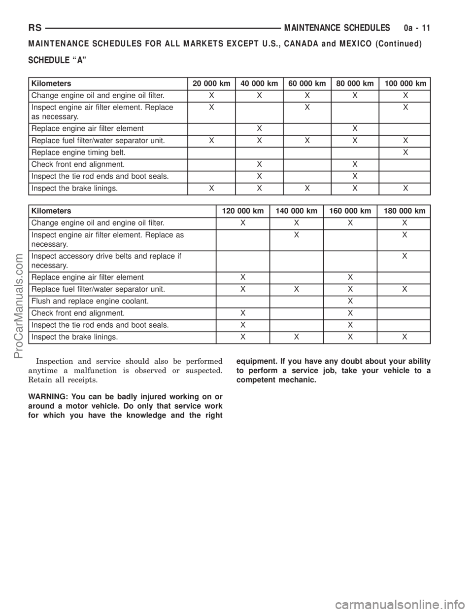
SCHEDULE ªAº
Kilometers 20 000 km 40 000 km 60 000 km 80 000 km 100 000 km
Change engine oil and engine oil filter.XXXX X
Inspect engine air filter element. Replace
as necessary.XX X
Replace engine air filter element X X
Replace fuel filter/water separator unit.XXXX X
Replace engine timing belt.X
Check front end alignment. X X
Inspect the tie rod ends and boot seals. X X
Inspect the brake linings.XXXX X
Kilometers 120 000 km 140 000 km 160 000 km 180 000 km
Change engine oil and engine oil filter. X X X X
Inspect engine air filter element. Replace as
necessary.XX
Inspect accessory drive belts and replace if
necessary.X
Replace engine air filter element X X
Replace fuel filter/water separator unit. X X X X
Flush and replace engine coolant. X
Check front end alignment. X X
Inspect the tie rod ends and boot seals. X X
Inspect the brake linings. X X X X
Inspection and service should also be performed
anytime a malfunction is observed or suspected.
Retain all receipts.
WARNING: You can be badly injured working on or
around a motor vehicle. Do only that service work
for which you have the knowledge and the rightequipment. If you have any doubt about your ability
to perform a service job, take your vehicle to a
competent mechanic.
RSMAINTENANCE SCHEDULES0a-11
MAINTENANCE SCHEDULES FOR ALL MARKETS EXCEPT U.S., CANADA and MEXICO (Continued)
ProCarManuals.com
Page 52 of 2177
INSPECTION - STEERING KNUCKLE
Inspect the knuckle for the following:
²Cracks or breaks
²Dents or damage
²Stress marks indicating a bend
The front suspension knuckle is not a repairable
component of the vehicles front suspension. If bent,
broken or damaged in any way, do not attempt to
straighten or repair the steering knuckle. It must be
replaced.
If inspection leads to the hub and bearing, (Refer
to 2 - SUSPENSION/FRONT/HUB / BEARING -
DIAGNOSIS AND TESTING)
INSTALLATION - STEERING KNUCKLE
(1) If the hub and bearing needs to be installed in
the knuckle, place the hub and bearing squarely into
the center hole of the steering knuckle aligning the
threaded mounting holes of the hub and bearing with
the mounting holes in the steering knuckle. Install
the four mounting bolts and tighten them to a torque
of 65 N´m (45 ft. lbs.).
CAUTION: Before installing the knuckle on the ball
joint stud, wipe the ball joint stud and knuckle con-
tact area free of any grease or debris, otherwisedamage to the knuckle can occur. Use a clean shop
cloth with MoparTBrake Parts Cleaner applied to it
for proper cleaning. Do not spray the stud directly.
(2) Place the knuckle on the ball joint stud.
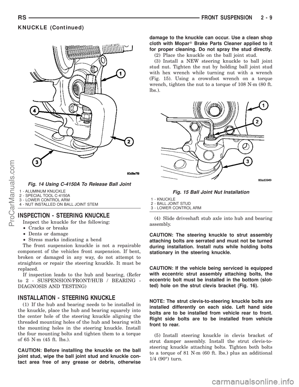
(3) Install a NEW steering knuckle to ball joint
stud nut. Tighten the nut by holding ball joint stud
with hex wrench while turning nut with a wrench
(Fig. 15). Using a crowsfoot wrench on a torque
wrench, tighten the nut to a torque of 108 N´m (80 ft.
lbs.).
(4) Slide driveshaft stub axle into hub and bearing
assembly.
CAUTION: The steering knuckle to strut assembly
attaching bolts are serrated and must not be turned
during installation. Install nuts while holding bolts
stationary in the steering knuckle.
CAUTION: If the vehicle being serviced is equipped
with eccentric strut assembly attaching bolts, the
eccentric bolt must be installed in the bottom (slot-
ted) hole on the strut clevis bracket (Fig. 16).
NOTE: The strut clevis-to-steering knuckle bolts are
installed differently on each side. Left hand side
bolts are to be installed from vehicle rear to front.
Right side bolts are to be installed from vehicle
front to rear.
(5) Install steering knuckle in clevis bracket of
strut damper assembly. Install the strut clevis-to-
steering knuckle attaching bolts. Tighten both bolts
to a torque of 81 N´m (60 ft. lbs.) plus an additional
1/4 (90É) turn.
Fig. 14 Using C-4150A To Release Ball Joint
1 - ALUMINUM KNUCKLE
2 - SPECIAL TOOL C-4150A
3 - LOWER CONTROL ARM
4 - NUT INSTALLED ON BALL JOINT STEMFig. 15 Ball Joint Nut Installation
1 - KNUCKLE
2 - BALL JOINT STUD
3 - LOWER CONTROL ARM
RSFRONT SUSPENSION2-9
KNUCKLE (Continued)
ProCarManuals.com
Page 57 of 2177
DISASSEMBLY - LOWER CONTROL ARM
(REAR BUSHING - HYDRO)
(1) Remove the lower control arm from the front
suspension cradle. (Refer to 2 - SUSPENSION/
FRONT/LOWER CONTROL ARM - REMOVAL)
(2) Mount the lower control arm in a visewithout
using excessive clamping force.
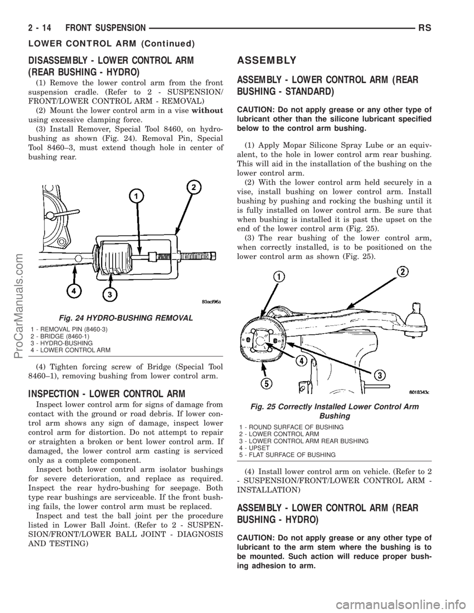
(3) Install Remover, Special Tool 8460, on hydro-
bushing as shown (Fig. 24). Removal Pin, Special
Tool 8460±3, must extend though hole in center of
bushing rear.
(4) Tighten forcing screw of Bridge (Special Tool
8460±1), removing bushing from lower control arm.
INSPECTION - LOWER CONTROL ARM
Inspect lower control arm for signs of damage from
contact with the ground or road debris. If lower con-
trol arm shows any sign of damage, inspect lower
control arm for distortion. Do not attempt to repair
or straighten a broken or bent lower control arm. If
damaged, the lower control arm casting is serviced
only as a complete component.
Inspect both lower control arm isolator bushings
for severe deterioration, and replace as required.
Inspect the rear hydro-bushing for seepage. Both
type rear bushings are serviceable. If the front bush-
ing fails, the lower control arm must be replaced.
Inspect and test the ball joint per the procedure
listed in Lower Ball Joint. (Refer to 2 - SUSPEN-
SION/FRONT/LOWER BALL JOINT - DIAGNOSIS
AND TESTING)
ASSEMBLY
ASSEMBLY - LOWER CONTROL ARM (REAR
BUSHING - STANDARD)
CAUTION: Do not apply grease or any other type of
lubricant other than the silicone lubricant specified
below to the control arm bushing.
(1) Apply Mopar Silicone Spray Lube or an equiv-
alent, to the hole in lower control arm rear bushing.
This will aid in the installation of the bushing on the
lower control arm.
(2) With the lower control arm held securely in a
vise, install bushing on lower control arm. Install
bushing by pushing and rocking the bushing until it
is fully installed on lower control arm. Be sure that
when bushing is installed it is past the upset on the
end of the lower control arm (Fig. 25).
(3) The rear bushing of the lower control arm,
when correctly installed, is to be positioned on the
lower control arm as shown (Fig. 25).
(4) Install lower control arm on vehicle. (Refer to 2
- SUSPENSION/FRONT/LOWER CONTROL ARM -
INSTALLATION)
ASSEMBLY - LOWER CONTROL ARM (REAR
BUSHING - HYDRO)
CAUTION: Do not apply grease or any other type of
lubricant to the arm stem where the bushing is to
be mounted. Such action will reduce proper bush-
ing adhesion to arm.
Fig. 24 HYDRO-BUSHING REMOVAL
1 - REMOVAL PIN (8460-3)
2 - BRIDGE (8460-1)
3 - HYDRO-BUSHING
4 - LOWER CONTROL ARM
Fig. 25 Correctly Installed Lower Control Arm
Bushing
1 - ROUND SURFACE OF BUSHING
2 - LOWER CONTROL ARM
3 - LOWER CONTROL ARM REAR BUSHING
4 - UPSET
5 - FLAT SURFACE OF BUSHING
2 - 14 FRONT SUSPENSIONRS
LOWER CONTROL ARM (Continued)
ProCarManuals.com
Page 94 of 2177
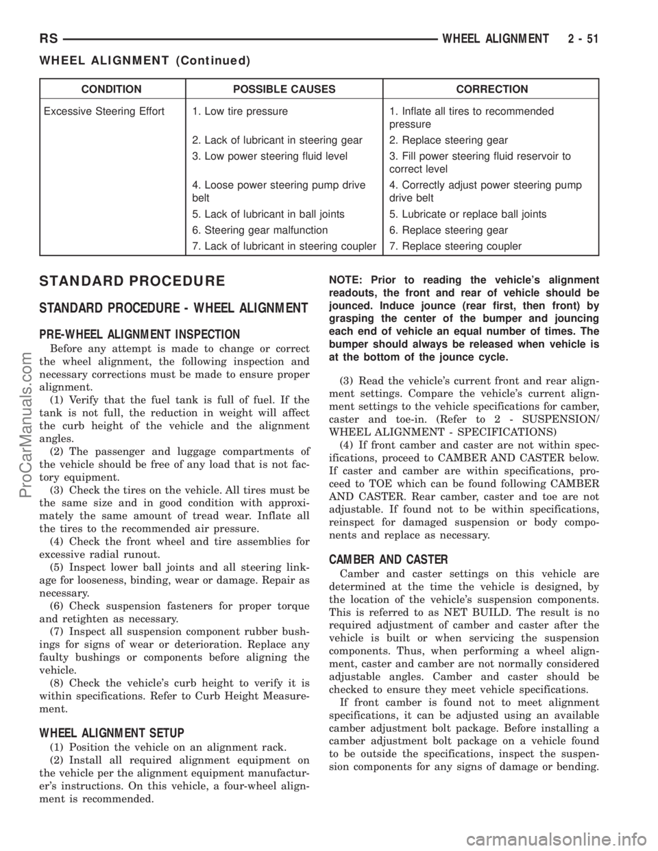
CONDITION POSSIBLE CAUSES CORRECTION
Excessive Steering Effort 1. Low tire pressure 1. Inflate all tires to recommended
pressure
2. Lack of lubricant in steering gear 2. Replace steering gear
3. Low power steering fluid level 3. Fill power steering fluid reservoir to
correct level
4. Loose power steering pump drive
belt4. Correctly adjust power steering pump
drive belt
5. Lack of lubricant in ball joints 5. Lubricate or replace ball joints
6. Steering gear malfunction 6. Replace steering gear
7. Lack of lubricant in steering coupler 7. Replace steering coupler
STANDARD PROCEDURE
STANDARD PROCEDURE - WHEEL ALIGNMENT
PRE-WHEEL ALIGNMENT INSPECTION
Before any attempt is made to change or correct
the wheel alignment, the following inspection and
necessary corrections must be made to ensure proper
alignment.
(1) Verify that the fuel tank is full of fuel. If the
tank is not full, the reduction in weight will affect
the curb height of the vehicle and the alignment
angles.
(2) The passenger and luggage compartments of
the vehicle should be free of any load that is not fac-
tory equipment.
(3) Check the tires on the vehicle. All tires must be
the same size and in good condition with approxi-
mately the same amount of tread wear. Inflate all
the tires to the recommended air pressure.
(4) Check the front wheel and tire assemblies for
excessive radial runout.
(5) Inspect lower ball joints and all steering link-
age for looseness, binding, wear or damage. Repair as
necessary.
(6) Check suspension fasteners for proper torque
and retighten as necessary.
(7) Inspect all suspension component rubber bush-
ings for signs of wear or deterioration. Replace any
faulty bushings or components before aligning the
vehicle.
(8) Check the vehicle's curb height to verify it is
within specifications. Refer to Curb Height Measure-
ment.
WHEEL ALIGNMENT SETUP
(1) Position the vehicle on an alignment rack.
(2) Install all required alignment equipment on
the vehicle per the alignment equipment manufactur-
er's instructions. On this vehicle, a four-wheel align-
ment is recommended.NOTE: Prior to reading the vehicle's alignment
readouts, the front and rear of vehicle should be
jounced. Induce jounce (rear first, then front) by
grasping the center of the bumper and jouncing
each end of vehicle an equal number of times. The
bumper should always be released when vehicle is
at the bottom of the jounce cycle.
(3) Read the vehicle's current front and rear align-
ment settings. Compare the vehicle's current align-
ment settings to the vehicle specifications for camber,
caster and toe-in. (Refer to 2 - SUSPENSION/
WHEEL ALIGNMENT - SPECIFICATIONS)
(4) If front camber and caster are not within spec-
ifications, proceed to CAMBER AND CASTER below.
If caster and camber are within specifications, pro-
ceed to TOE which can be found following CAMBER
AND CASTER. Rear camber, caster and toe are not
adjustable. If found not to be within specifications,
reinspect for damaged suspension or body compo-
nents and replace as necessary.
CAMBER AND CASTER
Camber and caster settings on this vehicle are
determined at the time the vehicle is designed, by
the location of the vehicle's suspension components.
This is referred to as NET BUILD. The result is no
required adjustment of camber and caster after the
vehicle is built or when servicing the suspension
components. Thus, when performing a wheel align-
ment, caster and camber are not normally considered
adjustable angles. Camber and caster should be
checked to ensure they meet vehicle specifications.
If front camber is found not to meet alignment
specifications, it can be adjusted using an available
camber adjustment bolt package. Before installing a
camber adjustment bolt package on a vehicle found
to be outside the specifications, inspect the suspen-
sion components for any signs of damage or bending.
RSWHEEL ALIGNMENT2-51
WHEEL ALIGNMENT (Continued)
ProCarManuals.com
Page 107 of 2177
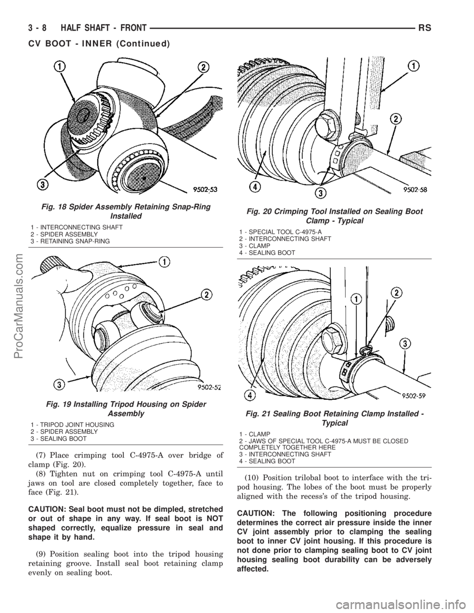
(7) Place crimping tool C-4975-A over bridge of
clamp (Fig. 20).
(8) Tighten nut on crimping tool C-4975-A until
jaws on tool are closed completely together, face to
face (Fig. 21).
CAUTION: Seal boot must not be dimpled, stretched
or out of shape in any way. If seal boot is NOT
shaped correctly, equalize pressure in seal and
shape it by hand.
(9) Position sealing boot into the tripod housing
retaining groove. Install seal boot retaining clamp
evenly on sealing boot.(10) Position trilobal boot to interface with the tri-
pod housing. The lobes of the boot must be properly
aligned with the recess's of the tripod housing.
CAUTION: The following positioning procedure
determines the correct air pressure inside the inner
CV joint assembly prior to clamping the sealing
boot to inner CV joint housing. If this procedure is
not done prior to clamping sealing boot to CV joint
housing sealing boot durability can be adversely
affected.
Fig. 18 Spider Assembly Retaining Snap-Ring
Installed
1 - INTERCONNECTING SHAFT
2 - SPIDER ASSEMBLY
3 - RETAINING SNAP-RING
Fig. 19 Installing Tripod Housing on Spider
Assembly
1 - TRIPOD JOINT HOUSING
2 - SPIDER ASSEMBLY
3 - SEALING BOOT
Fig. 20 Crimping Tool Installed on Sealing Boot
Clamp - Typical
1 - SPECIAL TOOL C-4975-A
2 - INTERCONNECTING SHAFT
3 - CLAMP
4 - SEALING BOOT
Fig. 21 Sealing Boot Retaining Clamp Installed -
Typical
1 - CLAMP
2 - JAWS OF SPECIAL TOOL C-4975-A MUST BE CLOSED
COMPLETELY TOGETHER HERE
3 - INTERCONNECTING SHAFT
4 - SEALING BOOT
3 - 8 HALF SHAFT - FRONTRS
CV BOOT - INNER (Continued)
ProCarManuals.com
Page 108 of 2177
CAUTION: When venting the inner CV joint assem-
bly, use care so that the inner CV sealing boot does
not get punctured, or in any other way damaged. If
sealing boot is punctured, or damaged in any way
while being vented, the sealing boot can not be
used.
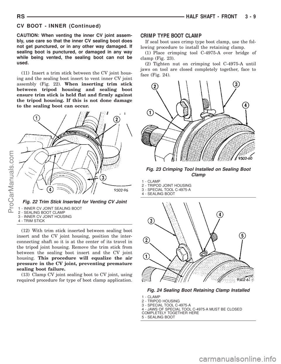
(11) Insert a trim stick between the CV joint hous-
ing and the sealing boot insert to vent inner CV joint
assembly (Fig. 22).When inserting trim stick
between tripod housing and sealing boot
ensure trim stick is held flat and firmly against
the tripod housing. If this is not done damage
to the sealing boot can occur.
(12) With trim stick inserted between sealing boot
insert and the CV joint housing, position the inter-
connecting shaft so it is at the center of its travel in
the tripod joint housing. Remove the trim stick from
between the sealing boot insert and the CV joint
housing.This procedure will equalize the air
pressure in the CV joint, preventing premature
sealing boot failure.
(13) Clamp CV joint sealing boot to CV joint, using
required procedure for type of boot clamp application.CRIMP TYPE BOOT CLAMP
If seal boot uses crimp type boot clamp, use the fol-
lowing procedure to install the retaining clamp.
(1) Place crimping tool C-4975-A over bridge of
clamp (Fig. 23).
(2) Tighten nut on crimping tool C-4975-A until
jaws on tool are closed completely together, face to
face (Fig. 24).
Fig. 22 Trim Stick Inserted for Venting CV Joint
1 - INNER CV JOINT SEALING BOOT
2 - SEALING BOOT CLAMP
3 - INNER CV JOINT HOUSING
4 - TRIM STICK
Fig. 23 Crimping Tool Installed on Sealing Boot
Clamp
1 - CLAMP
2 - TRIPOD JOINT HOUSING
3 - SPECIAL TOOL C-4975-A
4 - SEALING BOOT
Fig. 24 Sealing Boot Retaining Clamp Installed
1 - CLAMP
2 - TRIPOD HOUSING
3 - SPECIAL TOOL C-4975-A
4 - JAWS OF SPECIAL TOOL C-4975-A MUST BE CLOSED
COMPLETELY TOGETHER HERE
5 - SEALING BOOT
RSHALF SHAFT - FRONT3-9
CV BOOT - INNER (Continued)
ProCarManuals.com
Page 141 of 2177
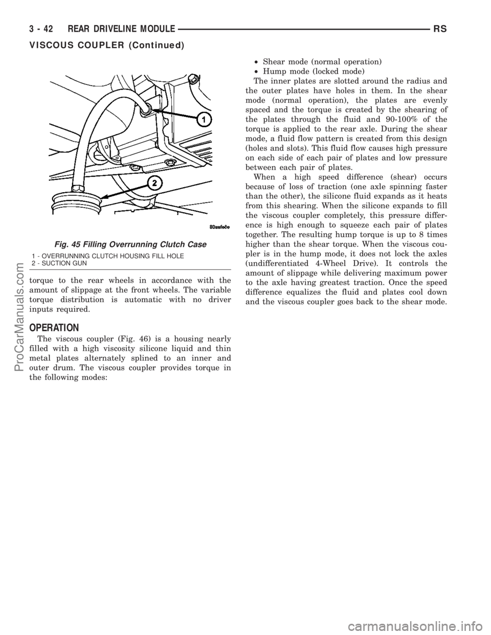
torque to the rear wheels in accordance with the
amount of slippage at the front wheels. The variable
torque distribution is automatic with no driver
inputs required.
OPERATION
The viscous coupler (Fig. 46) is a housing nearly
filled with a high viscosity silicone liquid and thin
metal plates alternately splined to an inner and
outer drum. The viscous coupler provides torque in
the following modes:²Shear mode (normal operation)
²Hump mode (locked mode)
The inner plates are slotted around the radius and
the outer plates have holes in them. In the shear
mode (normal operation), the plates are evenly
spaced and the torque is created by the shearing of
the plates through the fluid and 90-100% of the
torque is applied to the rear axle. During the shear
mode, a fluid flow pattern is created from this design
(holes and slots). This fluid flow causes high pressure
on each side of each pair of plates and low pressure
between each pair of plates.
When a high speed difference (shear) occurs
because of loss of traction (one axle spinning faster
than the other), the silicone fluid expands as it heats
from this shearing. When the silicone expands to fill
the viscous coupler completely, this pressure differ-
ence is high enough to squeeze each pair of plates
together. The resulting hump torque is up to 8 times
higher than the shear torque. When the viscous cou-
pler is in the hump mode, it does not lock the axles
(undifferentiated 4-Wheel Drive). It controls the
amount of slippage while delivering maximum power
to the axle having greatest traction. Once the speed
difference equalizes the fluid and plates cool down
and the viscous coupler goes back to the shear mode.
Fig. 45 Filling Overrunning Clutch Case
1 - OVERRUNNING CLUTCH HOUSING FILL HOLE
2 - SUCTION GUN
3 - 42 REAR DRIVELINE MODULERS
VISCOUS COUPLER (Continued)
ProCarManuals.com
Page 151 of 2177
WARNING
WARNING: DUST AND DIRT ACCUMULATING ON
BRAKE PARTS DURING NORMAL USE MAY CON-
TAIN ASBESTOS FIBERS FROM PRODUCTION OR
AFTERMARKET BRAKE LININGS. BREATHING
EXCESSIVE CONCENTRATIONS OF ASBESTOS
FIBERS CAN CAUSE SERIOUS BODILY HARM.
EXERCISE CARE WHEN SERVICING BRAKE
PARTS. DO NOT SAND OR GRIND BRAKE LINING
UNLESS EQUIPMENT USED IS DESIGNED TO CON-
TAIN THE DUST RESIDUE. DO NOT CLEAN BRAKE
PARTS WITH COMPRESSED AIR OR BY DRY
BRUSHING. CLEANING SHOULD BE DONE BY
DAMPENING THE BRAKE COMPONENTS WITH A
FINE MIST OF WATER, THEN WIPING THE BRAKE
COMPONENTS CLEAN WITH A DAMPENED CLOTH.
DISPOSE OF CLOTH AND ALL RESIDUE CONTAIN-
ING ASBESTOS FIBERS IN AN IMPERMEABLE
CONTAINER WITH THE APPROPRIATE LABEL. FOL-
LOW PRACTICES PRESCRIBED BY THE OCCUPA-
TIONAL SAFETY AND HEALTH ADMINISTRATION
(OSHA) AND THE ENVIRONMENTAL PROTECTION
AGENCY (EPA) FOR THE HANDLING, PROCESSING,
AND DISPOSING OF DUST OR DEBRIS THAT MAY
CONTAIN ASBESTOS FIBERS.
CAUTION
CAUTION: During service procedures, grease or
any other foreign material must be kept off brake
shoe assemblies, and braking surfaces of brake
rotor or drum, and external surfaces of hub and
bearing assembly.
CAUTION: Handling of brake rotors and calipers
must be done in such a way as to avoid damage to
the rotor and scratching or nicking of brake lining
on the brake shoes.
CAUTION: At no time when servicing a vehicle, can
a sheet metal screw, bolt or other metal fastener be
installed in the shock tower to take the place of an
original plastic clip. Also, NO holes can be drilled
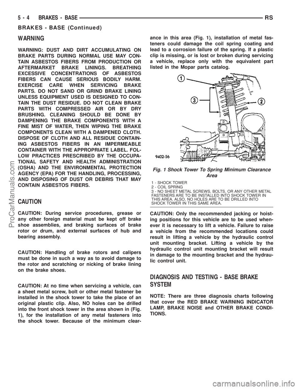
into the front shock tower in the area shown in (Fig.
1), for the installation of any metal fasteners into
the shock tower. Because of the minimum clear-ance in this area (Fig. 1), installation of metal fas-
teners could damage the coil spring coating and
lead to a corrosion failure of the spring. If a plastic
clip is missing, or is lost or broken during servicing
a vehicle, replace only with the equivalent part
listed in the Mopar parts catalog.
CAUTION: Only the recommended jacking or hoist-
ing positions for this vehicle are to be used when-
ever it is necessary to lift a vehicle. Failure to raise
a vehicle from the recommended locations could
result in lifting a vehicle by the hydraulic control
unit mounting bracket. Lifting a vehicle by the
hydraulic control unit mounting bracket will result
in damage to the mounting bracket and the hydrau-
lic control unit.
DIAGNOSIS AND TESTING - BASE BRAKE
SYSTEM
NOTE: There are three diagnosis charts following
that cover the RED BRAKE WARNING INDICATOR
LAMP, BRAKE NOISE and OTHER BRAKE CONDI-
TIONS.
Fig. 1 Shock Tower To Spring Minimum Clearance
Area
1 - SHOCK TOWER
2 - COIL SPRING
3 - NO SHEET METAL SCREWS, BOLTS, OR ANY OTHER METAL
FASTENERS ARE TO BE INSTALLED INTO SHOCK TOWER IN
THIS AREA. ALSO, NO HOLES ARE TO BE DRILLED INTO
SHOCK TOWER IN THIS SAME AREA.
5 - 4 BRAKES - BASERS
BRAKES - BASE (Continued)
ProCarManuals.com