air DODGE TOWN AND COUNTRY 2003 Owner's Guide
[x] Cancel search | Manufacturer: DODGE, Model Year: 2003, Model line: TOWN AND COUNTRY, Model: DODGE TOWN AND COUNTRY 2003Pages: 2177, PDF Size: 59.81 MB
Page 152 of 2177
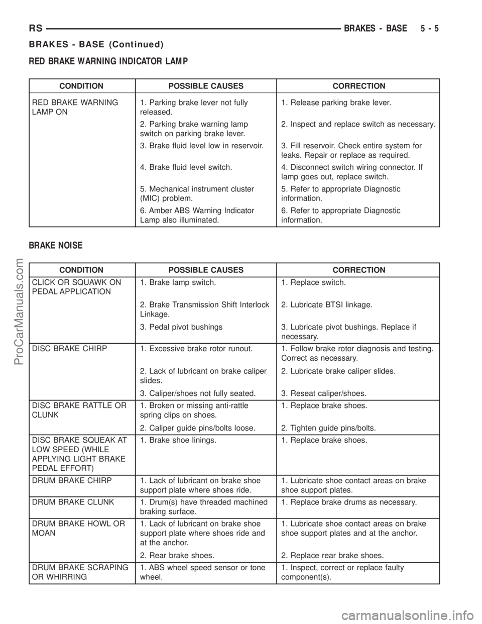
RED BRAKE WARNING INDICATOR LAMP
CONDITION POSSIBLE CAUSES CORRECTION
RED BRAKE WARNING
LAMP ON1. Parking brake lever not fully
released.1. Release parking brake lever.
2. Parking brake warning lamp
switch on parking brake lever.2. Inspect and replace switch as necessary.
3. Brake fluid level low in reservoir. 3. Fill reservoir. Check entire system for
leaks. Repair or replace as required.
4. Brake fluid level switch. 4. Disconnect switch wiring connector. If
lamp goes out, replace switch.
5. Mechanical instrument cluster
(MIC) problem.5. Refer to appropriate Diagnostic
information.
6. Amber ABS Warning Indicator
Lamp also illuminated.6. Refer to appropriate Diagnostic
information.
BRAKE NOISE
CONDITION POSSIBLE CAUSES CORRECTION
CLICK OR SQUAWK ON
PEDAL APPLICATION1. Brake lamp switch. 1. Replace switch.
2. Brake Transmission Shift Interlock
Linkage.2. Lubricate BTSI linkage.
3. Pedal pivot bushings 3. Lubricate pivot bushings. Replace if
necessary.
DISC BRAKE CHIRP 1. Excessive brake rotor runout. 1. Follow brake rotor diagnosis and testing.
Correct as necessary.
2. Lack of lubricant on brake caliper
slides.2. Lubricate brake caliper slides.
3. Caliper/shoes not fully seated. 3. Reseat caliper/shoes.
DISC BRAKE RATTLE OR
CLUNK1. Broken or missing anti-rattle
spring clips on shoes.1. Replace brake shoes.
2. Caliper guide pins/bolts loose. 2. Tighten guide pins/bolts.
DISC BRAKE SQUEAK AT
LOW SPEED (WHILE
APPLYING LIGHT BRAKE
PEDAL EFFORT)1. Brake shoe linings. 1. Replace brake shoes.
DRUM BRAKE CHIRP 1. Lack of lubricant on brake shoe
support plate where shoes ride.1. Lubricate shoe contact areas on brake
shoe support plates.
DRUM BRAKE CLUNK 1. Drum(s) have threaded machined
braking surface.1. Replace brake drums as necessary.
DRUM BRAKE HOWL OR
MOAN1. Lack of lubricant on brake shoe
support plate where shoes ride and
at the anchor.1. Lubricate shoe contact areas on brake
shoe support plates and at the anchor.
2. Rear brake shoes. 2. Replace rear brake shoes.
DRUM BRAKE SCRAPING
OR WHIRRING1. ABS wheel speed sensor or tone
wheel.1. Inspect, correct or replace faulty
component(s).
RSBRAKES - BASE5-5
BRAKES - BASE (Continued)
ProCarManuals.com
Page 153 of 2177
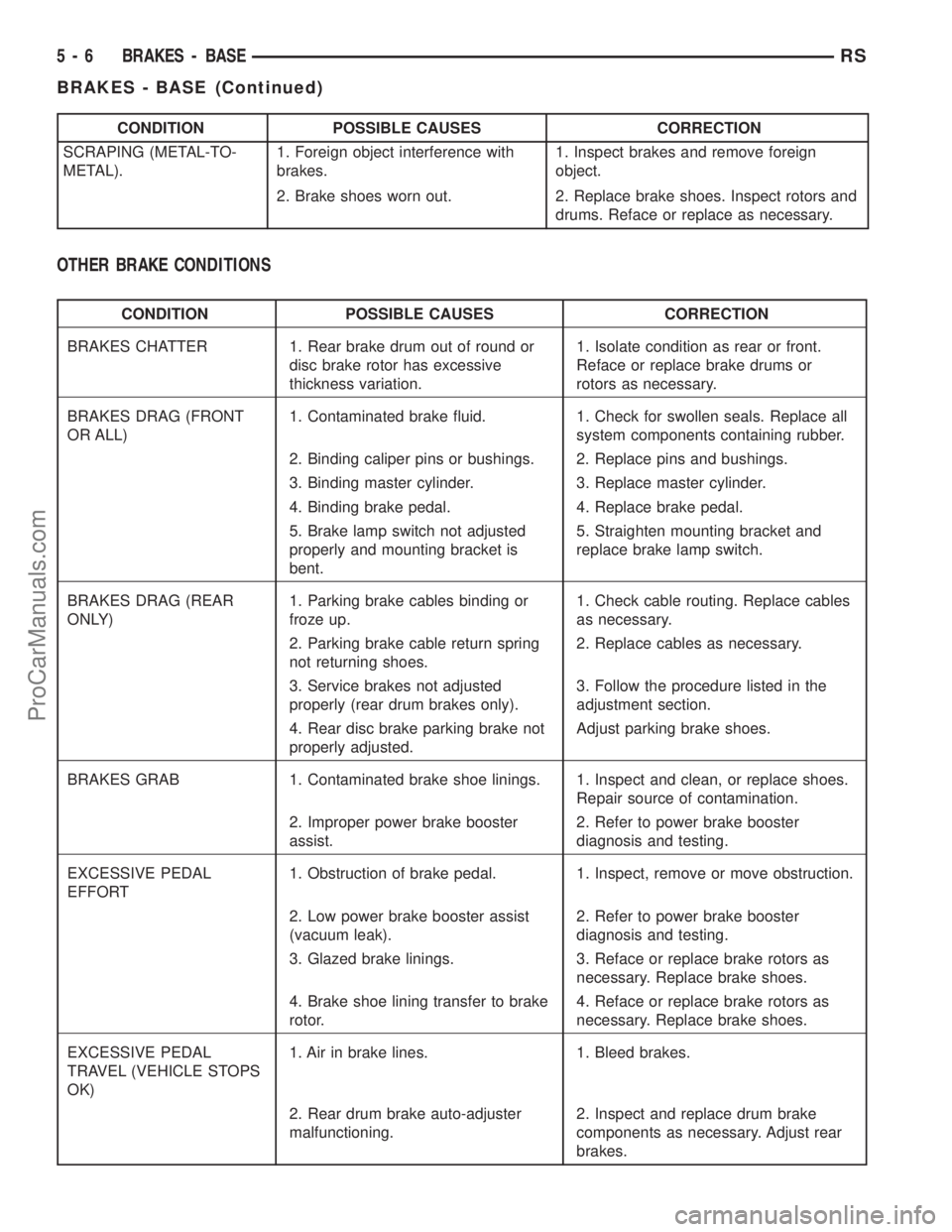
CONDITION POSSIBLE CAUSES CORRECTION
SCRAPING (METAL-TO-
METAL).1. Foreign object interference with
brakes.1. Inspect brakes and remove foreign
object.
2. Brake shoes worn out. 2. Replace brake shoes. Inspect rotors and
drums. Reface or replace as necessary.
OTHER BRAKE CONDITIONS
CONDITION POSSIBLE CAUSES CORRECTION
BRAKES CHATTER 1. Rear brake drum out of round or
disc brake rotor has excessive
thickness variation.1. Isolate condition as rear or front.
Reface or replace brake drums or
rotors as necessary.
BRAKES DRAG (FRONT
OR ALL)1. Contaminated brake fluid. 1. Check for swollen seals. Replace all
system components containing rubber.
2. Binding caliper pins or bushings. 2. Replace pins and bushings.
3. Binding master cylinder. 3. Replace master cylinder.
4. Binding brake pedal. 4. Replace brake pedal.
5. Brake lamp switch not adjusted
properly and mounting bracket is
bent.5. Straighten mounting bracket and
replace brake lamp switch.
BRAKES DRAG (REAR
ONLY)1. Parking brake cables binding or
froze up.1. Check cable routing. Replace cables
as necessary.
2. Parking brake cable return spring
not returning shoes.2. Replace cables as necessary.
3. Service brakes not adjusted
properly (rear drum brakes only).3. Follow the procedure listed in the
adjustment section.
4. Rear disc brake parking brake not
properly adjusted.Adjust parking brake shoes.
BRAKES GRAB 1. Contaminated brake shoe linings. 1. Inspect and clean, or replace shoes.
Repair source of contamination.
2. Improper power brake booster
assist.2. Refer to power brake booster
diagnosis and testing.
EXCESSIVE PEDAL
EFFORT1. Obstruction of brake pedal. 1. Inspect, remove or move obstruction.
2. Low power brake booster assist
(vacuum leak).2. Refer to power brake booster
diagnosis and testing.
3. Glazed brake linings. 3. Reface or replace brake rotors as
necessary. Replace brake shoes.
4. Brake shoe lining transfer to brake
rotor.4. Reface or replace brake rotors as
necessary. Replace brake shoes.
EXCESSIVE PEDAL
TRAVEL (VEHICLE STOPS
OK)1. Air in brake lines. 1. Bleed brakes.
2. Rear drum brake auto-adjuster
malfunctioning.2. Inspect and replace drum brake
components as necessary. Adjust rear
brakes.
5 - 6 BRAKES - BASERS
BRAKES - BASE (Continued)
ProCarManuals.com
Page 154 of 2177
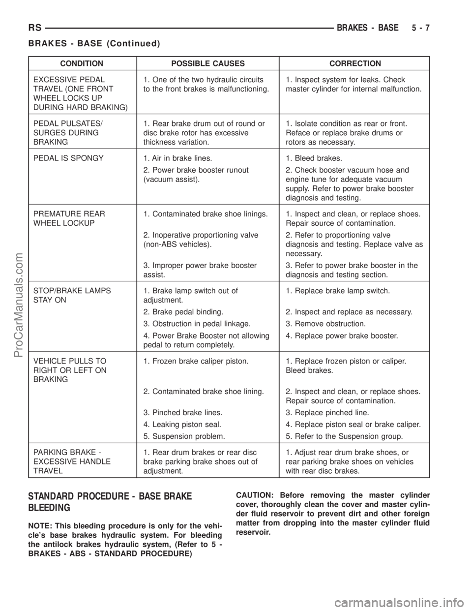
CONDITION POSSIBLE CAUSES CORRECTION
EXCESSIVE PEDAL
TRAVEL (ONE FRONT
WHEEL LOCKS UP
DURING HARD BRAKING)1. One of the two hydraulic circuits
to the front brakes is malfunctioning.1. Inspect system for leaks. Check
master cylinder for internal malfunction.
PEDAL PULSATES/
SURGES DURING
BRAKING1. Rear brake drum out of round or
disc brake rotor has excessive
thickness variation.1. Isolate condition as rear or front.
Reface or replace brake drums or
rotors as necessary.
PEDAL IS SPONGY 1. Air in brake lines. 1. Bleed brakes.
2. Power brake booster runout
(vacuum assist).2. Check booster vacuum hose and
engine tune for adequate vacuum
supply. Refer to power brake booster
diagnosis and testing.
PREMATURE REAR
WHEEL LOCKUP1. Contaminated brake shoe linings. 1. Inspect and clean, or replace shoes.
Repair source of contamination.
2. Inoperative proportioning valve
(non-ABS vehicles).2. Refer to proportioning valve
diagnosis and testing. Replace valve as
necessary.
3. Improper power brake booster
assist.3. Refer to power brake booster in the
diagnosis and testing section.
STOP/BRAKE LAMPS
S TAY O N1. Brake lamp switch out of
adjustment.1. Replace brake lamp switch.
2. Brake pedal binding. 2. Inspect and replace as necessary.
3. Obstruction in pedal linkage. 3. Remove obstruction.
4. Power Brake Booster not allowing
pedal to return completely.4. Replace power brake booster.
VEHICLE PULLS TO
RIGHT OR LEFT ON
BRAKING1. Frozen brake caliper piston. 1. Replace frozen piston or caliper.
Bleed brakes.
2. Contaminated brake shoe lining. 2. Inspect and clean, or replace shoes.
Repair source of contamination.
3. Pinched brake lines. 3. Replace pinched line.
4. Leaking piston seal. 4. Replace piston seal or brake caliper.
5. Suspension problem. 5. Refer to the Suspension group.
PARKING BRAKE -
EXCESSIVE HANDLE
TRAVEL1. Rear drum brakes or rear disc
brake parking brake shoes out of
adjustment.1. Adjust rear drum brake shoes, or
rear parking brake shoes on vehicles
with rear disc brakes.
STANDARD PROCEDURE - BASE BRAKE
BLEEDING
NOTE: This bleeding procedure is only for the vehi-
cle's base brakes hydraulic system. For bleeding
the antilock brakes hydraulic system, (Refer to 5 -
BRAKES - ABS - STANDARD PROCEDURE)CAUTION: Before removing the master cylinder
cover, thoroughly clean the cover and master cylin-
der fluid reservoir to prevent dirt and other foreign
matter from dropping into the master cylinder fluid
reservoir.
RSBRAKES - BASE5-7
BRAKES - BASE (Continued)
ProCarManuals.com
Page 155 of 2177
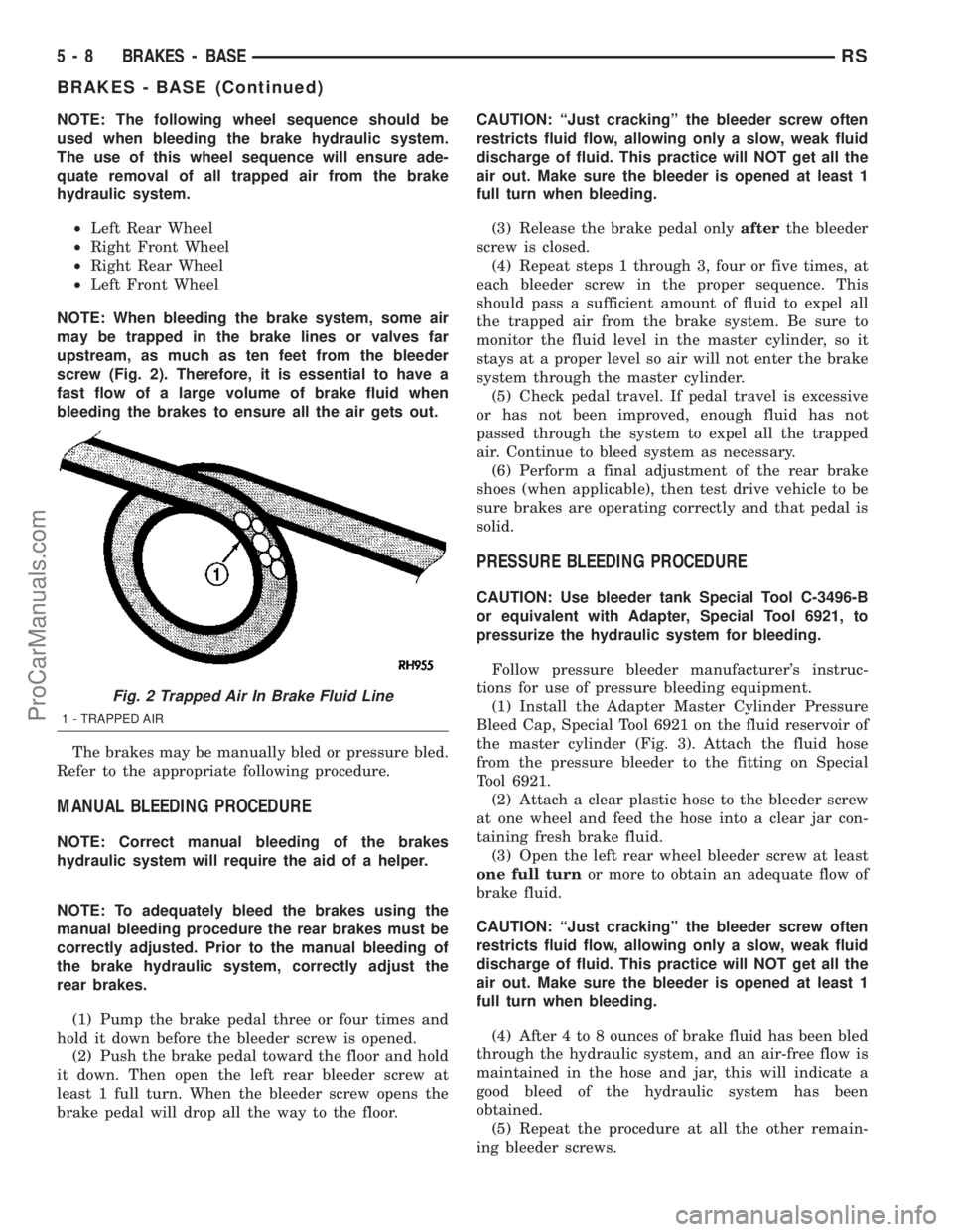
NOTE: The following wheel sequence should be
used when bleeding the brake hydraulic system.
The use of this wheel sequence will ensure ade-
quate removal of all trapped air from the brake
hydraulic system.
²Left Rear Wheel
²Right Front Wheel
²Right Rear Wheel
²Left Front Wheel
NOTE: When bleeding the brake system, some air
may be trapped in the brake lines or valves far
upstream, as much as ten feet from the bleeder
screw (Fig. 2). Therefore, it is essential to have a
fast flow of a large volume of brake fluid when
bleeding the brakes to ensure all the air gets out.
The brakes may be manually bled or pressure bled.
Refer to the appropriate following procedure.
MANUAL BLEEDING PROCEDURE
NOTE: Correct manual bleeding of the brakes
hydraulic system will require the aid of a helper.
NOTE: To adequately bleed the brakes using the
manual bleeding procedure the rear brakes must be
correctly adjusted. Prior to the manual bleeding of
the brake hydraulic system, correctly adjust the
rear brakes.
(1) Pump the brake pedal three or four times and
hold it down before the bleeder screw is opened.
(2) Push the brake pedal toward the floor and hold
it down. Then open the left rear bleeder screw at
least 1 full turn. When the bleeder screw opens the
brake pedal will drop all the way to the floor.CAUTION: ªJust crackingº the bleeder screw often
restricts fluid flow, allowing only a slow, weak fluid
discharge of fluid. This practice will NOT get all the
air out. Make sure the bleeder is opened at least 1
full turn when bleeding.
(3) Release the brake pedal onlyafterthe bleeder
screw is closed.
(4) Repeat steps 1 through 3, four or five times, at
each bleeder screw in the proper sequence. This
should pass a sufficient amount of fluid to expel all
the trapped air from the brake system. Be sure to
monitor the fluid level in the master cylinder, so it
stays at a proper level so air will not enter the brake
system through the master cylinder.
(5) Check pedal travel. If pedal travel is excessive
or has not been improved, enough fluid has not
passed through the system to expel all the trapped
air. Continue to bleed system as necessary.
(6) Perform a final adjustment of the rear brake
shoes (when applicable), then test drive vehicle to be
sure brakes are operating correctly and that pedal is
solid.
PRESSURE BLEEDING PROCEDURE
CAUTION: Use bleeder tank Special Tool C-3496-B
or equivalent with Adapter, Special Tool 6921, to
pressurize the hydraulic system for bleeding.
Follow pressure bleeder manufacturer's instruc-
tions for use of pressure bleeding equipment.
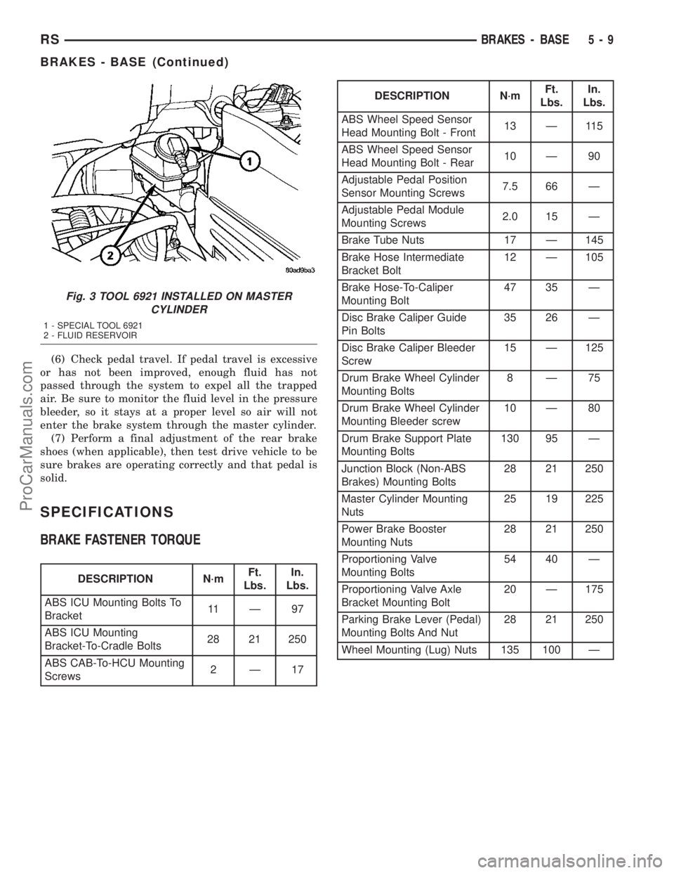
(1) Install the Adapter Master Cylinder Pressure
Bleed Cap, Special Tool 6921 on the fluid reservoir of
the master cylinder (Fig. 3). Attach the fluid hose
from the pressure bleeder to the fitting on Special
Tool 6921.
(2) Attach a clear plastic hose to the bleeder screw
at one wheel and feed the hose into a clear jar con-
taining fresh brake fluid.
(3) Open the left rear wheel bleeder screw at least
one full turnor more to obtain an adequate flow of
brake fluid.
CAUTION: ªJust crackingº the bleeder screw often
restricts fluid flow, allowing only a slow, weak fluid
discharge of fluid. This practice will NOT get all the
air out. Make sure the bleeder is opened at least 1
full turn when bleeding.
(4) After 4 to 8 ounces of brake fluid has been bled
through the hydraulic system, and an air-free flow is
maintained in the hose and jar, this will indicate a
good bleed of the hydraulic system has been
obtained.
(5) Repeat the procedure at all the other remain-
ing bleeder screws.
Fig. 2 Trapped Air In Brake Fluid Line
1 - TRAPPED AIR
5 - 8 BRAKES - BASERS
BRAKES - BASE (Continued)
ProCarManuals.com
Page 156 of 2177
(6) Check pedal travel. If pedal travel is excessive
or has not been improved, enough fluid has not
passed through the system to expel all the trapped
air. Be sure to monitor the fluid level in the pressure
bleeder, so it stays at a proper level so air will not
enter the brake system through the master cylinder.
(7) Perform a final adjustment of the rear brake
shoes (when applicable), then test drive vehicle to be
sure brakes are operating correctly and that pedal is
solid.
SPECIFICATIONS
BRAKE FASTENER TORQUE
DESCRIPTION N´mFt.
Lbs.In.
Lbs.
ABS ICU Mounting Bolts To
Bracket11 Ð 9 7
ABS ICU Mounting
Bracket-To-Cradle Bolts28 21 250
ABS CAB-To-HCU Mounting
Screws2Ð17
DESCRIPTION N´mFt.
Lbs.In.
Lbs.
ABS Wheel Speed Sensor
Head Mounting Bolt - Front13 Ð 115
ABS Wheel Speed Sensor
Head Mounting Bolt - Rear10 Ð 90
Adjustable Pedal Position
Sensor Mounting Screws7.5 66 Ð
Adjustable Pedal Module
Mounting Screws2.0 15 Ð
Brake Tube Nuts 17 Ð 145
Brake Hose Intermediate
Bracket Bolt12 Ð 105
Brake Hose-To-Caliper
Mounting Bolt47 35 Ð
Disc Brake Caliper Guide
Pin Bolts35 26 Ð
Disc Brake Caliper Bleeder
Screw15 Ð 125
Drum Brake Wheel Cylinder
Mounting Bolts8Ð75
Drum Brake Wheel Cylinder
Mounting Bleeder screw10 Ð 80
Drum Brake Support Plate
Mounting Bolts130 95 Ð
Junction Block (Non-ABS
Brakes) Mounting Bolts28 21 250
Master Cylinder Mounting
Nuts25 19 225
Power Brake Booster
Mounting Nuts28 21 250
Proportioning Valve
Mounting Bolts54 40 Ð
Proportioning Valve Axle
Bracket Mounting Bolt20 Ð 175
Parking Brake Lever (Pedal)
Mounting Bolts And Nut28 21 250
Wheel Mounting (Lug) Nuts 135 100 Ð
Fig. 3 TOOL 6921 INSTALLED ON MASTER
CYLINDER
1 - SPECIAL TOOL 6921
2 - FLUID RESERVOIR
RSBRAKES - BASE5-9
BRAKES - BASE (Continued)
ProCarManuals.com
Page 163 of 2177
CLEANING - DISC BRAKE SHOES
WARNING: DUST AND DIRT ACCUMULATING ON
BRAKE PARTS DURING NORMAL USE MAY CON-
TAIN ASBESTOS FIBERS FROM PRODUCTION OR
AFTERMARKET BRAKE LININGS. BREATHING
EXCESSIVE CONCENTRATIONS OF ASBESTOS
FIBERS CAN CAUSE SERIOUS BODILY HARM.
EXERCISE CARE WHEN SERVICING BRAKE
PARTS. DO NOT SAND OR GRIND BRAKE LINING
UNLESS EQUIPMENT USED IS DESIGNED TO CON-
TAIN THE DUST RESIDUE. DO NOT CLEAN BRAKE
PARTS WITH COMPRESSED AIR OR BY DRY
BRUSHING. CLEANING SHOULD BE DONE BY
DAMPENING THE BRAKE COMPONENTS WITH A
FINE MIST OF WATER, THEN WIPING THE BRAKE
COMPONENTS CLEAN WITH A DAMPENED CLOTH.
DISPOSE OF CLOTH AND ALL RESIDUE CONTAIN-
ING ASBESTOS FIBERS IN AN IMPERMEABLE
CONTAINER WITH THE APPROPRIATE LABEL. FOL-
LOW PRACTICES PRESCRIBED BY THE OCCUPA-
TIONAL SAFETY AND HEALTH ADMINISTRATION
(OSHA) AND THE ENVIRONMENTAL PROTECTION
AGENCY (EPA) FOR THE HANDLING, PROCESSING,
AND DISPOSING OF DUST OR DEBRIS THAT MAY
CONTAIN ASBESTOS FIBERS.
INSPECTION - DISC BRAKE SHOES
Visually inspect brake shoes (pads) for uneven lin-
ing wear. Also inspect for excessive lining deteriora-
tion. Check the clearance between the tips of the
wear indicators on the shoes (if equipped) and the
brake rotors.
If a visual inspection does not adequately deter-
mine the condition of the lining, a physical check will
be necessary. To check the amount of lining wear,
remove the disc brake shoes from the calipers.
Measure each brake shoe. The combined brake
shoe and its lining material thickness should be mea-
sured at its thinnest point.
²For front disc brake shoes, when a set of brake
shoes are worn to a thickness of approximately 7.95
mm (5/16 inch), they should be replaced.
²For rear disc brake shoes, when a set of brake
shoes are worn to a thickness of approximately 7.0
mm (9/32 inch), they should be replaced.
²Typically, if front shoes are worn out, both fronts
and rears need to be replaced. Make sure to check
rears.
Replacebothdisc brake shoes (inboard and out-
board) on each caliper. It is necessary to replace the
shoes on the opposite side of the vehicle as well as
the shoes failing inspection.If the brake shoe assemblies do not require
replacement, be sure to reinstall the brake shoes in
the original position they were removed from.
INSTALLATION
INSTALLATION - FRONT DISC BRAKE SHOES
(DISC/DISC BRAKES)
NOTE: There may be more than 1 lining material
released. Make sure proper linings are being
installed.
(1) Begin on one side of the vehicle or the other.
(2) Completely retract the caliper piston back into
its bore in the brake caliper (This is required for cal-
iper installation on the brake rotor with new brake
shoes installed).
(3) If applied, remove the protective paper from
the noise suppression gasket on the rear of both the
inner and outer brake shoe assemblies.
(4) Install the new inboard brake shoe into the cal-
iper piston by firmly pressing its retaining clip into
the piston bore. Be sure the inboard brake shoe is
positioned squarely against the face of the caliper
piston.
(5) Lubricate both adapter abutments where the
shoes slide with a small amount of MopartDielectric
grease, or equivalent.
(6) Slide the new outboard brake shoe into the cal-
iper adapter with the lining up against the outside of
the brake rotor.
CAUTION: Use care when installing the caliper
assembly onto the caliper adapter, so the caliper
guide pin bushings do not get damaged by the
adapter bosses.
(7) Carefully position the brake caliper over the
brake rotor and adapter.
(8) Install the caliper guide pin bolts and tighten
to a torque of 35 N´m (26 ft. lbs.).Extreme caution
should be taken not to cross thread the caliper
guide pin bolts.
(9) Install the caps over the caliper guide pin bolts.
(10) Install the new caliper hold down spring (anti-
rattle clip) on the outboard side of the caliper. Start
the spring into the holes on the caliper, then stretch
the clip legs past the abutments on the caliper
adapter.
(11) Repeat the above procedure on other side of
the vehicle.
(12) Install the wheel and tire assemblies. Tighten
the wheel mounting nuts in proper sequence until all
nuts are torqued to half specification, then repeat the
5 - 16 BRAKES - BASERS
BRAKE PADS/SHOES - FRONT (Continued)
ProCarManuals.com
Page 165 of 2177
(7) Remove the outboard brake shoe from the cali-
per. Brake shoe is removed by pushing the shoe
toward the piston, disengaging the two metal protru-
sions on the shoe back, then sliding the brake shoe
off the caliper.
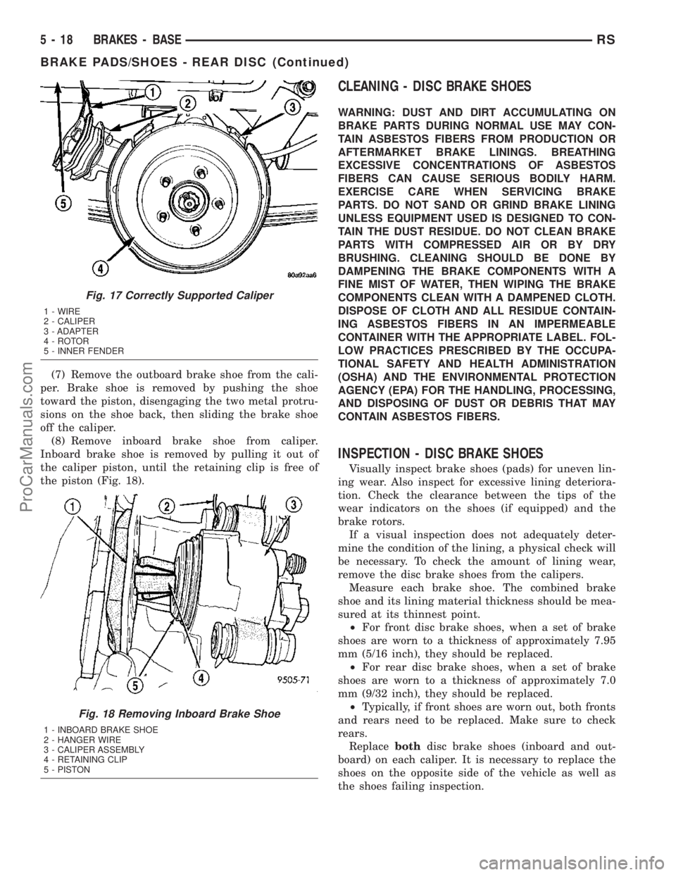
(8) Remove inboard brake shoe from caliper.
Inboard brake shoe is removed by pulling it out of
the caliper piston, until the retaining clip is free of
the piston (Fig. 18).
CLEANING - DISC BRAKE SHOES
WARNING: DUST AND DIRT ACCUMULATING ON
BRAKE PARTS DURING NORMAL USE MAY CON-
TAIN ASBESTOS FIBERS FROM PRODUCTION OR
AFTERMARKET BRAKE LININGS. BREATHING
EXCESSIVE CONCENTRATIONS OF ASBESTOS
FIBERS CAN CAUSE SERIOUS BODILY HARM.
EXERCISE CARE WHEN SERVICING BRAKE
PARTS. DO NOT SAND OR GRIND BRAKE LINING
UNLESS EQUIPMENT USED IS DESIGNED TO CON-
TAIN THE DUST RESIDUE. DO NOT CLEAN BRAKE
PARTS WITH COMPRESSED AIR OR BY DRY
BRUSHING. CLEANING SHOULD BE DONE BY
DAMPENING THE BRAKE COMPONENTS WITH A
FINE MIST OF WATER, THEN WIPING THE BRAKE
COMPONENTS CLEAN WITH A DAMPENED CLOTH.
DISPOSE OF CLOTH AND ALL RESIDUE CONTAIN-
ING ASBESTOS FIBERS IN AN IMPERMEABLE
CONTAINER WITH THE APPROPRIATE LABEL. FOL-
LOW PRACTICES PRESCRIBED BY THE OCCUPA-
TIONAL SAFETY AND HEALTH ADMINISTRATION
(OSHA) AND THE ENVIRONMENTAL PROTECTION
AGENCY (EPA) FOR THE HANDLING, PROCESSING,
AND DISPOSING OF DUST OR DEBRIS THAT MAY
CONTAIN ASBESTOS FIBERS.
INSPECTION - DISC BRAKE SHOES
Visually inspect brake shoes (pads) for uneven lin-
ing wear. Also inspect for excessive lining deteriora-
tion. Check the clearance between the tips of the
wear indicators on the shoes (if equipped) and the
brake rotors.
If a visual inspection does not adequately deter-
mine the condition of the lining, a physical check will
be necessary. To check the amount of lining wear,
remove the disc brake shoes from the calipers.
Measure each brake shoe. The combined brake
shoe and its lining material thickness should be mea-
sured at its thinnest point.
²For front disc brake shoes, when a set of brake
shoes are worn to a thickness of approximately 7.95
mm (5/16 inch), they should be replaced.
²For rear disc brake shoes, when a set of brake
shoes are worn to a thickness of approximately 7.0
mm (9/32 inch), they should be replaced.
²Typically, if front shoes are worn out, both fronts
and rears need to be replaced. Make sure to check
rears.
Replacebothdisc brake shoes (inboard and out-
board) on each caliper. It is necessary to replace the
shoes on the opposite side of the vehicle as well as
the shoes failing inspection.
Fig. 17 Correctly Supported Caliper
1 - WIRE
2 - CALIPER
3 - ADAPTER
4 - ROTOR
5 - INNER FENDER
Fig. 18 Removing Inboard Brake Shoe
1 - INBOARD BRAKE SHOE
2 - HANGER WIRE
3 - CALIPER ASSEMBLY
4 - RETAINING CLIP
5 - PISTON
5 - 18 BRAKES - BASERS
BRAKE PADS/SHOES - REAR DISC (Continued)
ProCarManuals.com
Page 166 of 2177
If the brake shoe assemblies do not require
replacement, be sure to reinstall the brake shoes in
the original position they were removed from.
INSTALLATION - REAR DISC BRAKE SHOES
(1) Completely retract caliper piston back into pis-
ton bore of caliper assembly.
(2) Lubricate both adapter abutments where the
shoes contact with a liberal amount of MopartMul-
tipurpose Lubricant, or equivalent.
(3) If removed, install the brake rotor on the hub,
making sure it is squarely seated on the face of the
hub.
(4) Install the inboard brake shoe into the caliper
piston by firmly pressing it into the piston bore using
your thumbs. Be sure inboard brake shoe is posi-
tioned squarely against the face of the caliper piston.
NOTE: The outboard shoes are different left to
right. They can be identified by a L or R stamped on
the clip.
(5) Install the outboard brake shoe on the disc
brake caliper. Be sure the outboard shoe is positioned
squarely against the outboard fingers of the caliper.
CAUTION: Use care when installing the caliper
assembly onto the adapter, so the caliper guide pin
bushings do not get damaged by the mounting
bosses.
(6) Carefully lower caliper and brake shoes over
rotor and onto adapter, reversing the removal proce-
dure (Fig. 16).
CAUTION: When installing the caliper guide pin
bolts extreme caution should be taken not to
crossthread the guide pin bolts.
(7) Install the caliper guide pin bolts. Tighten the
guide pin bolts to a torque of 35 N´m (26 ft. lbs.).
(8) Install the wheel and tire assembly. Tighten
the wheel mounting nuts in proper sequence until all
nuts are torqued to half specification. Then repeat
the tightening sequence to the full specified torque of
135 N´m (100 ft. lbs.).
(9) Lower vehicle.
CAUTION: Before moving vehicle, pump the brake
pedal several times to insure the vehicle has a firm
brake pedal to adequately stop the vehicle.
(10) Pump brake pedal several times to set brake
shoes to rotors.(11) Check fluid level in reservoir.
(12) Road test the vehicle and make several stops
to wear off any foreign material on the brakes and to
seat the brake shoe linings.BRAKE PADS/SHOES - REAR
DRUM
REMOVAL - REAR DRUM BRAKE SHOES
(1) Raise vehicle. (Refer to LUBRICATION &
MAINTENANCE/HOISTING - STANDARD PROCE-
DURE).
(2) Remove the rear wheel and tire assemblies
from the vehicle.
(3) Remove rear brake drum to hub retaining clips
(if equipped), then remove rear brake drums. (Refer
to 5 - BRAKES/HYDRAULIC/MECHANICAL/DRUM
- REMOVAL)
NOTE: When creating slack in the park brake cables
by locking out the automatic adjuster, (Fig. 19) be
sure that the park brake pedal is in the released
(most upward) position.
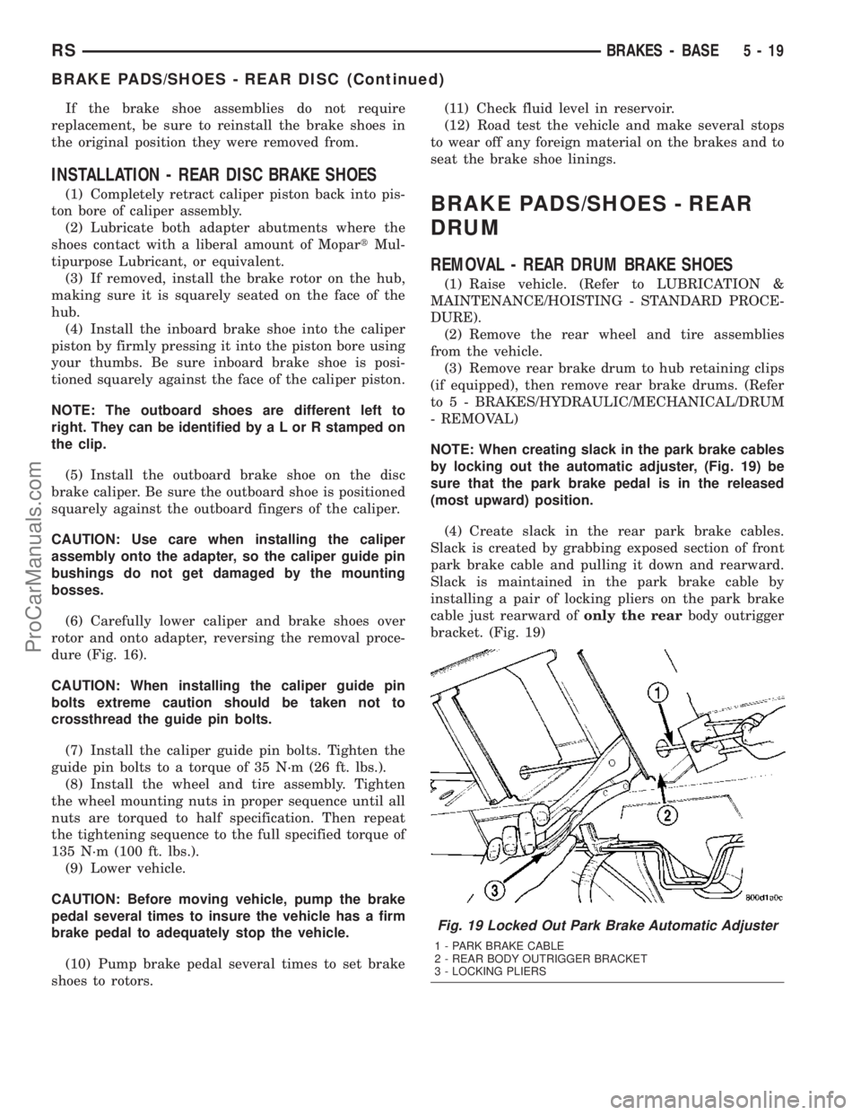
(4) Create slack in the rear park brake cables.
Slack is created by grabbing exposed section of front
park brake cable and pulling it down and rearward.
Slack is maintained in the park brake cable by
installing a pair of locking pliers on the park brake
cable just rearward ofonly the rearbody outrigger
bracket. (Fig. 19)
Fig. 19 Locked Out Park Brake Automatic Adjuster
1 - PARK BRAKE CABLE
2 - REAR BODY OUTRIGGER BRACKET
3 - LOCKING PLIERS
RSBRAKES - BASE5-19
BRAKE PADS/SHOES - REAR DISC (Continued)
ProCarManuals.com
Page 171 of 2177
DISC BRAKE CALIPER -
FRONT
REMOVAL
REMOVAL - FRONT DISC BRAKE CALIPER
(DISC/DISC BRAKES)
(1) Depress the brake pedal past its first inch of
travel and hold it in this position using a brake pedal
depressor (holding) tool. This is done to isolate the
master cylinder from the brake hydraulic system dis-
allowing the brake fluid to completely drain out of
the brake fluid reservoir.
(2) Raise the vehicle. (Refer to LUBRICATION &
MAINTENANCE/HOISTING - STANDARD PROCE-
DURE).
(3) Remove front wheel and tire assembly.
(4) Remove the banjo bolt connecting the brake
hose to the brake caliper. There are two washers (one
on each side of the brake hose fitting) that will come
off with the banjo bolt. Discard these washers.
(5) Remove the 2 caliper guide pin bolts.
(6) Remove the brake caliper from the adapter.
REMOVAL - FRONT DISC BRAKE CALIPER
(DISC/DRUM BRAKES)
(1) Using a brake pedal holding tool, depress the
brake pedal past its first one inch of travel and hold
it in this position. This will isolate the master cylin-
der from the brake hydraulic system and will not
allow the brake fluid to drain out of the master cyl-
inder reservoir when the lines are opened.
(2) Raise the vehicle. Refer to HOISTING in
LUBRICATION AND MAINTENANCE.
(3) Remove the front tire and wheel assembly.
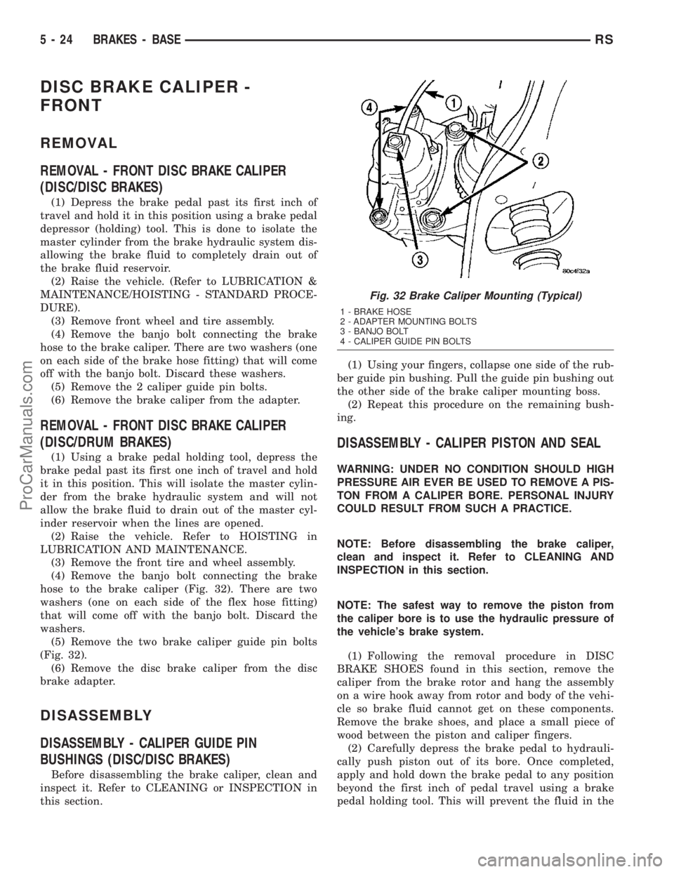
(4) Remove the banjo bolt connecting the brake
hose to the brake caliper (Fig. 32). There are two
washers (one on each side of the flex hose fitting)
that will come off with the banjo bolt. Discard the
washers.
(5) Remove the two brake caliper guide pin bolts
(Fig. 32).
(6) Remove the disc brake caliper from the disc
brake adapter.
DISASSEMBLY
DISASSEMBLY - CALIPER GUIDE PIN
BUSHINGS (DISC/DISC BRAKES)
Before disassembling the brake caliper, clean and
inspect it. Refer to CLEANING or INSPECTION in
this section.(1) Using your fingers, collapse one side of the rub-
ber guide pin bushing. Pull the guide pin bushing out
the other side of the brake caliper mounting boss.
(2) Repeat this procedure on the remaining bush-
ing.
DISASSEMBLY - CALIPER PISTON AND SEAL
WARNING: UNDER NO CONDITION SHOULD HIGH
PRESSURE AIR EVER BE USED TO REMOVE A PIS-
TON FROM A CALIPER BORE. PERSONAL INJURY
COULD RESULT FROM SUCH A PRACTICE.
NOTE: Before disassembling the brake caliper,
clean and inspect it. Refer to CLEANING AND
INSPECTION in this section.
NOTE: The safest way to remove the piston from
the caliper bore is to use the hydraulic pressure of
the vehicle's brake system.
(1) Following the removal procedure in DISC
BRAKE SHOES found in this section, remove the
caliper from the brake rotor and hang the assembly
on a wire hook away from rotor and body of the vehi-
cle so brake fluid cannot get on these components.
Remove the brake shoes, and place a small piece of
wood between the piston and caliper fingers.
(2) Carefully depress the brake pedal to hydrauli-
cally push piston out of its bore. Once completed,
apply and hold down the brake pedal to any position
beyond the first inch of pedal travel using a brake
pedal holding tool. This will prevent the fluid in the
Fig. 32 Brake Caliper Mounting (Typical)
1 - BRAKE HOSE
2 - ADAPTER MOUNTING BOLTS
3 - BANJO BOLT
4 - CALIPER GUIDE PIN BOLTS
5 - 24 BRAKES - BASERS
ProCarManuals.com
Page 172 of 2177
master cylinder reservoir from completely draining
out.
(3) Disconnect the brake fluid flex hose from the
caliper assembly and remove it from the vehicle.
CAUTION: Do not use excessive force when clamp-
ing caliper in vise. Excessive vise pressure will
cause bore distortion.
(4) Mount the caliper in a vise equipped with pro-
tective jaws.
(5) Remove the piston dust boot from the caliper
and discard.
NOTE: Do not use a screw driver or other metal tool
for seal removal. Using such tools can scratch the
bore or leave burrs on the seal groove edges.
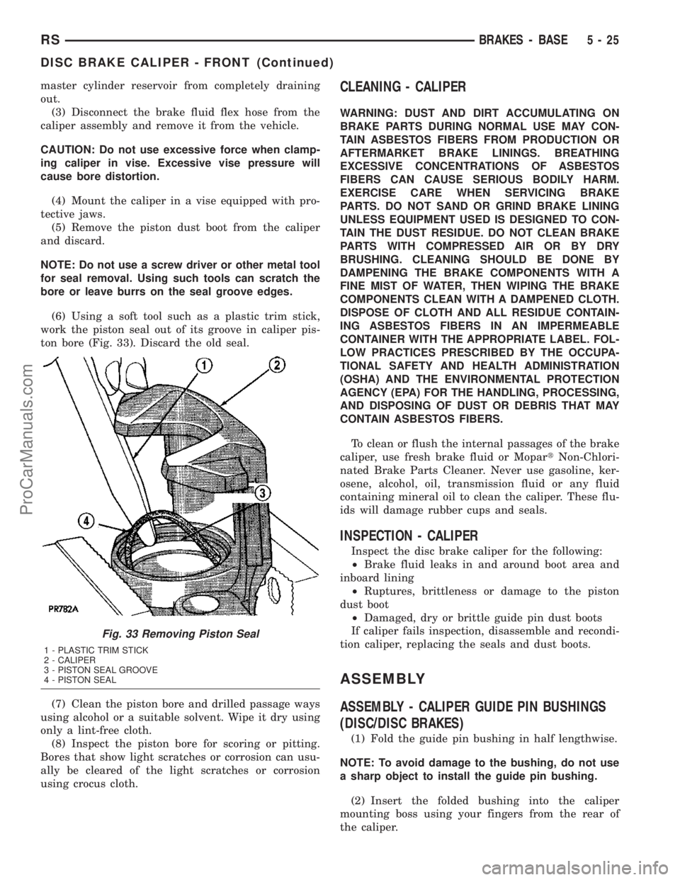
(6) Using a soft tool such as a plastic trim stick,
work the piston seal out of its groove in caliper pis-
ton bore (Fig. 33). Discard the old seal.
(7) Clean the piston bore and drilled passage ways
using alcohol or a suitable solvent. Wipe it dry using
only a lint-free cloth.
(8) Inspect the piston bore for scoring or pitting.
Bores that show light scratches or corrosion can usu-
ally be cleared of the light scratches or corrosion
using crocus cloth.CLEANING - CALIPER
WARNING: DUST AND DIRT ACCUMULATING ON
BRAKE PARTS DURING NORMAL USE MAY CON-
TAIN ASBESTOS FIBERS FROM PRODUCTION OR
AFTERMARKET BRAKE LININGS. BREATHING
EXCESSIVE CONCENTRATIONS OF ASBESTOS
FIBERS CAN CAUSE SERIOUS BODILY HARM.
EXERCISE CARE WHEN SERVICING BRAKE
PARTS. DO NOT SAND OR GRIND BRAKE LINING
UNLESS EQUIPMENT USED IS DESIGNED TO CON-
TAIN THE DUST RESIDUE. DO NOT CLEAN BRAKE
PARTS WITH COMPRESSED AIR OR BY DRY
BRUSHING. CLEANING SHOULD BE DONE BY
DAMPENING THE BRAKE COMPONENTS WITH A
FINE MIST OF WATER, THEN WIPING THE BRAKE
COMPONENTS CLEAN WITH A DAMPENED CLOTH.
DISPOSE OF CLOTH AND ALL RESIDUE CONTAIN-
ING ASBESTOS FIBERS IN AN IMPERMEABLE
CONTAINER WITH THE APPROPRIATE LABEL. FOL-
LOW PRACTICES PRESCRIBED BY THE OCCUPA-
TIONAL SAFETY AND HEALTH ADMINISTRATION
(OSHA) AND THE ENVIRONMENTAL PROTECTION
AGENCY (EPA) FOR THE HANDLING, PROCESSING,
AND DISPOSING OF DUST OR DEBRIS THAT MAY
CONTAIN ASBESTOS FIBERS.
To clean or flush the internal passages of the brake
caliper, use fresh brake fluid or MopartNon-Chlori-
nated Brake Parts Cleaner. Never use gasoline, ker-
osene, alcohol, oil, transmission fluid or any fluid
containing mineral oil to clean the caliper. These flu-
ids will damage rubber cups and seals.
INSPECTION - CALIPER
Inspect the disc brake caliper for the following:
²Brake fluid leaks in and around boot area and
inboard lining
²Ruptures, brittleness or damage to the piston
dust boot
²Damaged, dry or brittle guide pin dust boots
If caliper fails inspection, disassemble and recondi-
tion caliper, replacing the seals and dust boots.
ASSEMBLY
ASSEMBLY - CALIPER GUIDE PIN BUSHINGS
(DISC/DISC BRAKES)
(1) Fold the guide pin bushing in half lengthwise.
NOTE: To avoid damage to the bushing, do not use
a sharp object to install the guide pin bushing.
(2) Insert the folded bushing into the caliper
mounting boss using your fingers from the rear of
the caliper.
Fig. 33 Removing Piston Seal
1 - PLASTIC TRIM STICK
2 - CALIPER
3 - PISTON SEAL GROOVE
4 - PISTON SEAL
RSBRAKES - BASE5-25
DISC BRAKE CALIPER - FRONT (Continued)
ProCarManuals.com