DODGE TOWN AND COUNTRY 2003 Service Manual
Manufacturer: DODGE, Model Year: 2003, Model line: TOWN AND COUNTRY, Model: DODGE TOWN AND COUNTRY 2003Pages: 2177, PDF Size: 59.81 MB
Page 401 of 2177
(1) Install target magnet in end of camshaft.
Tighten mounting screw to 3 N´m (30 in. lbs.) torque.
Over torqueing could cause cracks in magnet. If mag-
net cracks replace it.
(2) Install camshaft position sensor. Tighten sensor
mounting screws to 12.9 N´m (115 in. lbs.) torque.
(3) Carefully attach electrical connector to cam-
shaft position sensor.
(4) Connect the negative battery cable.
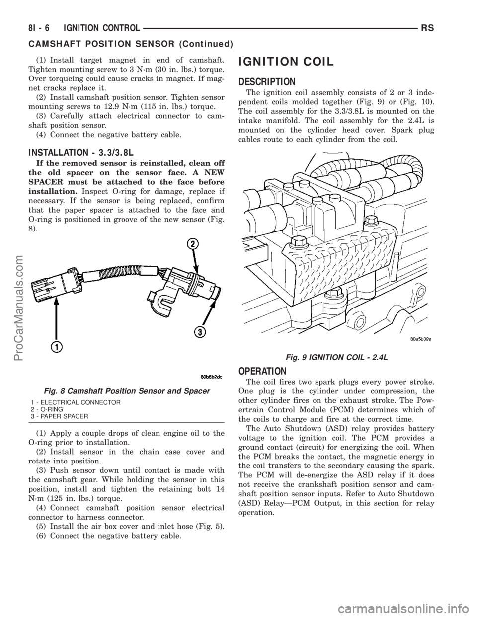
INSTALLATION - 3.3/3.8L
If the removed sensor is reinstalled, clean off
the old spacer on the sensor face. A NEW
SPACER must be attached to the face before
installation.Inspect O-ring for damage, replace if
necessary. If the sensor is being replaced, confirm
that the paper spacer is attached to the face and
O-ring is positioned in groove of the new sensor (Fig.
8).
(1) Apply a couple drops of clean engine oil to the
O-ring prior to installation.
(2) Install sensor in the chain case cover and
rotate into position.
(3) Push sensor down until contact is made with
the camshaft gear. While holding the sensor in this
position, install and tighten the retaining bolt 14
N´m (125 in. lbs.) torque.
(4) Connect camshaft position sensor electrical
connector to harness connector.
(5) Install the air box cover and inlet hose (Fig. 5).
(6) Connect the negative battery cable.
IGNITION COIL
DESCRIPTION
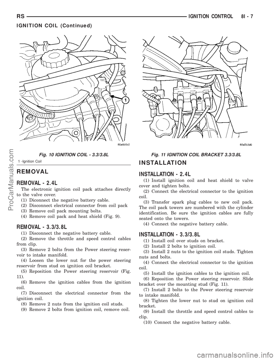
The ignition coil assembly consists of 2 or 3 inde-
pendent coils molded together (Fig. 9) or (Fig. 10).
The coil assembly for the 3.3/3.8L is mounted on the
intake manifold. The coil assembly for the 2.4L is
mounted on the cylinder head cover. Spark plug
cables route to each cylinder from the coil.
OPERATION
The coil fires two spark plugs every power stroke.
One plug is the cylinder under compression, the
other cylinder fires on the exhaust stroke. The Pow-
ertrain Control Module (PCM) determines which of
the coils to charge and fire at the correct time.
The Auto Shutdown (ASD) relay provides battery
voltage to the ignition coil. The PCM provides a
ground contact (circuit) for energizing the coil. When
the PCM breaks the contact, the magnetic energy in
the coil transfers to the secondary causing the spark.
The PCM will de-energize the ASD relay if it does
not receive the crankshaft position sensor and cam-
shaft position sensor inputs. Refer to Auto Shutdown
(ASD) RelayÐPCM Output, in this section for relay
operation.
Fig. 8 Camshaft Position Sensor and Spacer
1 - ELECTRICAL CONNECTOR
2 - O-RING
3 - PAPER SPACER
Fig. 9 IGNITION COIL - 2.4L
8I - 6 IGNITION CONTROLRS
CAMSHAFT POSITION SENSOR (Continued)
ProCarManuals.com
Page 402 of 2177
REMOVAL
REMOVAL - 2.4L
The electronic ignition coil pack attaches directly
to the valve cover.
(1) Diconnect the negative battery cable.
(2) Disconnect electrical connector from coil pack
(3) Remove coil pack mounting bolts.
(4) Remove coil pack and heat shield (Fig. 9).
REMOVAL - 3.3/3.8L
(1) Disconnect the negative battery cable.
(2) Remove the throttle and speed control cables
from clip.
(3) Remove 2 bolts from the Power steering reser-
voir to intake manifold.
(4) Loosen the lower nut for the power steering
reservoir from stud on ignition coil bracket.
(5) Reposition the Power steering reservoir (Fig.
11).
(6) Remove the ignition cables from the ignition
coil.
(7) Disconnect the electrical connector from the
ignition coil.
(8) Remove 2 nuts from the ignition coil studs.
(9) Remove 2 bolts from ignition coil, remove coil.
INSTALLATION
INSTALLATION - 2.4L
(1) Install ignition coil and heat shield to valve
cover and tighten bolts.
(2) Connect the electrical connector to the ignition
coil.
(3) Transfer spark plug cables to new coil pack.
The coil pack towers are numbered with the cylinder
identification. Be sure the ignition cables are fully
seated onto the towers.
(4) Connect the negative battery cable.
INSTALLATION - 3.3/3.8L
(1) Install coil over studs on bracket.
(2) Install 2 bolts to ignition coil.
(3) Install 2 nuts to the ignition coil studs. Tighten
nuts and bolts.
(4) Connect the electrical connector to the ignition
coil.
(5) Install the ignition cables to the ignition coil.
(6) Reposition the Power steering reservoir. Slide
bracket over the mounting stud (Fig. 11).
(7) Install 2 bolts to the Power steering reservoir
to intake manifold.
(8) Tighten the lower nut to stud on ignition coil
bracket.
(9) Install the throttle and speed control cables to
clip.
(10) Connect the negative battery cable.
Fig. 10 IGNITION COIL - 3.3/3.8L
1 -Ignition Coil
Fig. 11 IGNITION COIL BRACKET 3.3/3.8L
RSIGNITION CONTROL8I-7
IGNITION COIL (Continued)
ProCarManuals.com
Page 403 of 2177
KNOCK SENSOR
DESCRIPTION
The knock sensor threads into the cylinder block.
The knock sensor is designed to detect engine vibra-
tion that is caused by detonation.
OPERATION
When the knock sensor detects a knock in one of
the cylinders, it sends an input signal to the PCM. In
response, the PCM retards ignition timing for all cyl-
inders by a scheduled amount.
Knock sensors contain a piezoelectric material
which constantly vibrates and sends an input voltage
(signal) to the PCM while the engine operates. As the
intensity of the crystal's vibration increases, the
knock sensor output voltage also increases.
The voltage signal produced by the knock sensor
increases with the amplitude of vibration. The PCM
receives as an input the knock sensor voltage signal.
If the signal rises above a predetermined level, the
PCM will store that value in memory and retard
ignition timing to reduce engine knock. If the knock
sensor voltage exceeds a preset value, the PCM
retards ignition timing for all cylinders. It is not a
selective cylinder retard.
The PCM ignores knock sensor input during engine
idle conditions. Once the engine speed exceeds a
specified value, knock retard is allowed.
Knock retard uses its own short term and long
term memory program.
Long term memory stores previous detonation
information in its battery-backed RAM. The maxi-
mum authority that long term memory has over tim-
ing retard can be calibrated.
Short term memory is allowed to retard timing up
to a preset amount under all operating conditions (as
long as rpm is above the minimum rpm) except WOT.
The PCM, using short term memory, can respond
quickly to retard timing when engine knock is
detected. Short term memory is lost any time the
ignition key is turned off.
NOTE: Over or under tightening affects knock sen-
sor performance, possibly causing improper spark
control.
REMOVAL
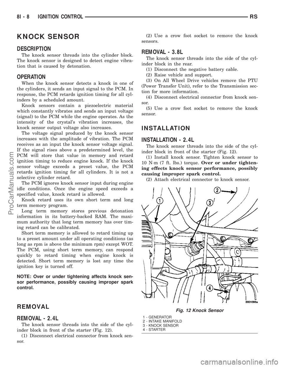
REMOVAL - 2.4L
The knock sensor threads into the side of the cyl-
inder block in front of the starter (Fig. 12).
(1) Disconnect electrical connector from knock sen-
sor.(2) Use a crow foot socket to remove the knock
sensors.
REMOVAL - 3.8L
The knock sensor threads into the side of the cyl-
inder block in the rear.
(1) Disconnect the negative battery cable.
(2) Raise vehicle and support.
(3) On All Wheel Drive vehicles remove the PTU
(Power Transfer Unit), refer to the Transmission sec-
tion for more information.
(4) Disconnect electrical connector from knock sen-
sor.
(5) Use a crow foot socket to remove the knock
sensor.
INSTALLATION
INSTALLATION - 2.4L
The knock sensor threads into the side of the cyl-
inder block in front of the starter (Fig. 12).
(1) Install knock sensor. Tighten knock sensor to
10 N´m (7 ft. lbs.) torque.Over or under tighten-
ing effects knock sensor performance, possibly
causing improper spark control.
(2) Attach electrical connector to knock sensor.
Fig. 12 Knock Sensor
1 - GENERATOR
2 - INTAKE MANIFOLD
3 - KNOCK SENSOR
4-STARTER
8I - 8 IGNITION CONTROLRS
ProCarManuals.com
Page 404 of 2177
INSTALLATION - 3.8L
The knock sensor threads into the side of the cyl-
inder block in the rear.
(1) Install knock sensor. Tighten knock sensor to
10 N´m (7 ft. lbs.) torque.Over or under tighten-
ing effects knock sensor performance, possibly
causing improper spark control.
(2) Attach electrical connector to knock sensor.
(3) On All Wheel Drive vehicles install the PTU
(Power Transfer Unit) for the rear wheels, refer to
the Transmission section for more information.
(4) Lower vehicle.
(5) Connect the negative cable.
SPARK PLUG
DESCRIPTION
DESCRIPTION - STANDARD 4 CYLINDER
All engines use resistor spark plugs. They have
resistance values ranging from 6,000 to 20,000 ohms
when checked with at least a 1000 volt spark plug
tester.
Do not use an ohm meter to check the resis-
tance of the spark plugs. This will give an inac-
curate reading.
Refer to the Specifications section for gap and type
of spark plug.
DESCRIPTION - PLATINUM PLUGS
The V6 engines use platinum resistor spark plugs.
They have resistance values of 6,000 to 20,000 ohms
when checked with at least a 1000 volt tester. For
spark plug identification and specifications, Refer to
the Specifications section.
Do not use an ohm meter to check the resis-
tance of the spark plugs. This will give an inac-
curate reading.
When the spark plugs use a single or double plat-
inum tips and they have a recommended service life
of 100,000 miles for normal driving conditions per
schedule A in this manual. The spark plugs have a
recommended service life of 75,000 miles for severe
driving conditions per schedule B in this manual. A
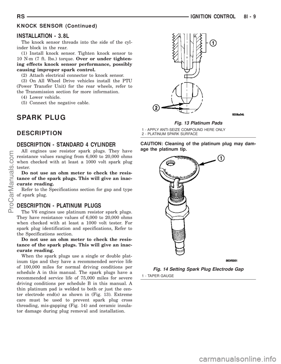
thin platinum pad is welded to both or just the cen-
ter electrode end(s) as shown in (Fig. 13). Extreme
care must be used to prevent spark plug cross
threading, mis-gapping (Fig. 14) and ceramic insula-
tor damage during plug removal and installation.CAUTION: Cleaning of the platinum plug may dam-
age the platinum tip.
Fig. 13 Platinum Pads
1 - APPLY ANTI-SEIZE COMPOUND HERE ONLY
2 - PLATINUM SPARK SURFACE
Fig. 14 Setting Spark Plug Electrode Gap
1 - TAPER GAUGE
RSIGNITION CONTROL8I-9
KNOCK SENSOR (Continued)
ProCarManuals.com
Page 405 of 2177

REMOVAL
When replacing the spark plugs and spark plug
cables, route the cables correctly and secure them in
the appropriate retainers. Failure to route the cables
properly can cause the radio to reproduce ignition
noise, cross ignition of the spark plugs orshort cir-
cuit the cables to ground.
Always remove cables by grasping at the boot,
rotating the boot 1/2 turn, and pulling straight back
in a steady motion.
(1) Prior to removing the spark plug, spray com-
pressed air around the spark plug hole and the area
around the spark plug.
(2) Remove the spark plug using a quality socket
with a foam insert.
(3) Inspect the spark plug condition.
INSTALLATION
When replacing the spark plugs and spark plug
cables, route the cables correctly and secure them in
the appropriate retainers. Failure to route the cables
properly can cause the radio to reproduce ignition
noise, cross ignition of the spark plugs orshort cir-
cuit the cables to ground.
(1) Coat threads of spark plug with anti-seize. Be
sure not to get anti-seizeANTWHERE BUT ON
THE THREADS OF THE SPARK PLUG as
shown in (Fig. 13).
(2) To avoid cross threading, start the spark plug
into the cylinder head by hand.
(3) Tighten spark plugs to 17.5 N´m (13 ft. lbs.)
torque.
(4) Install spark plug cables over spark plugs. A
click will be heard and felt when the cable properly
attaches to the spark plug.
SPARK PLUG CABLE
DESCRIPTION
Spark Plug cables are sometimes referred to as
secondary ignition wires. The wires transfer electri-
cal current from the ignition coil pack to individual
spark plugs at each cylinder. The resistive spark plug
cables are of nonmetallic construction. The cables
provide suppression of radio frequency emissions
from the ignition system.
Check the spark plug cable connections for good
contact at the coil, and spark plugs. Terminals should
be fully seated. The insulators should be in good con-
dition and should fit tightly on the coil, and spark
plugs. Spark plug cables with insulators that are
cracked or torn must be replaced.
Clean Spark Plug cables with a cloth moistened
with a non-flammable solvent. Wipe the cables dry.
Check for brittle or cracked insulation. The spark
plug cables and spark plug boots are made from high
temperature materials.
REMOVAL - 2.0/2.4L
Failure to route the cables properly could cause the
radio to reproduce ignition noise, cross ignition of the
spark plugs or short circuit the cables to ground.
Remove spark plug cable from coil first.
Always remove the spark plug cable by grasping
the top of the spark plug insulator, turning the boot
1/2 turn and pulling straight up in a steady motion.
INSTALLATION - 2.0/2.4L
Failure to route the cables properly could cause the
radio to reproduce ignition noise, cross ignition of the
spark plugs or short circuit the cables to ground.
Install spark plug insulators over spark plugs.
Ensure the top of the spark plug insulator covers the
upper end of the spark plug tube, then connect the
other end to coil pack.
8I - 10 IGNITION CONTROLRS
SPARK PLUG (Continued)
ProCarManuals.com
Page 406 of 2177
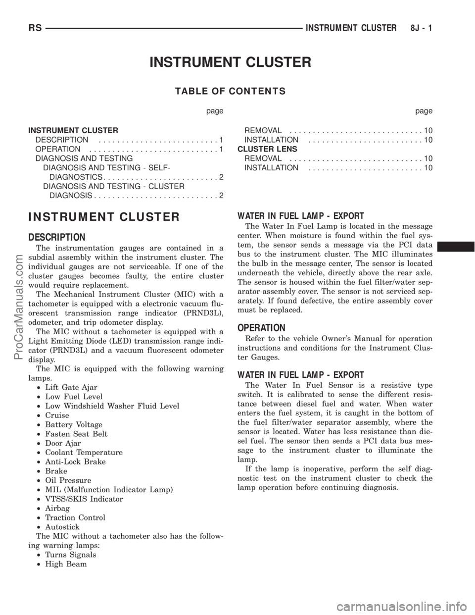
INSTRUMENT CLUSTER
TABLE OF CONTENTS
page page
INSTRUMENT CLUSTER
DESCRIPTION..........................1
OPERATION............................1
DIAGNOSIS AND TESTING
DIAGNOSIS AND TESTING - SELF-
DIAGNOSTICS.........................2
DIAGNOSIS AND TESTING - CLUSTER
DIAGNOSIS...........................2REMOVAL.............................10
INSTALLATION.........................10
CLUSTER LENS
REMOVAL.............................10
INSTALLATION.........................10
INSTRUMENT CLUSTER
DESCRIPTION
The instrumentation gauges are contained in a
subdial assembly within the instrument cluster. The
individual gauges are not serviceable. If one of the
cluster gauges becomes faulty, the entire cluster
would require replacement.
The Mechanical Instrument Cluster (MIC) with a
tachometer is equipped with a electronic vacuum flu-
orescent transmission range indicator (PRND3L),
odometer, and trip odometer display.
The MIC without a tachometer is equipped with a
Light Emitting Diode (LED) transmission range indi-
cator (PRND3L) and a vacuum fluorescent odometer
display.
The MIC is equipped with the following warning
lamps.
²Lift Gate Ajar
²Low Fuel Level
²Low Windshield Washer Fluid Level
²Cruise
²Battery Voltage
²Fasten Seat Belt
²Door Ajar
²Coolant Temperature
²Anti-Lock Brake
²Brake
²Oil Pressure
²MIL (Malfunction Indicator Lamp)
²VTSS/SKIS Indicator
²Airbag
²Traction Control
²Autostick
The MIC without a tachometer also has the follow-
ing warning lamps:
²Turns Signals
²High Beam
WATER IN FUEL LAMP - EXPORT
The Water In Fuel Lamp is located in the message
center. When moisture is found within the fuel sys-
tem, the sensor sends a message via the PCI data
bus to the instrument cluster. The MIC illuminates
the bulb in the message center, The sensor is located
underneath the vehicle, directly above the rear axle.
The sensor is housed within the fuel filter/water sep-
arator assembly cover. The sensor is not serviced sep-
arately. If found defective, the entire assembly cover
must be replaced.
OPERATION
Refer to the vehicle Owner's Manual for operation
instructions and conditions for the Instrument Clus-
ter Gauges.
WATER IN FUEL LAMP - EXPORT
The Water In Fuel Sensor is a resistive type
switch. It is calibrated to sense the different resis-
tance between diesel fuel and water. When water
enters the fuel system, it is caught in the bottom of
the fuel filter/water separator assembly, where the
sensor is located. Water has less resistance than die-
sel fuel. The sensor then sends a PCI data bus mes-
sage to the instrument cluster to illuminate the
lamp.
If the lamp is inoperative, perform the self diag-
nostic test on the instrument cluster to check the
lamp operation before continuing diagnosis.
RSINSTRUMENT CLUSTER8J-1
ProCarManuals.com
Page 407 of 2177
DIAGNOSIS AND TESTING
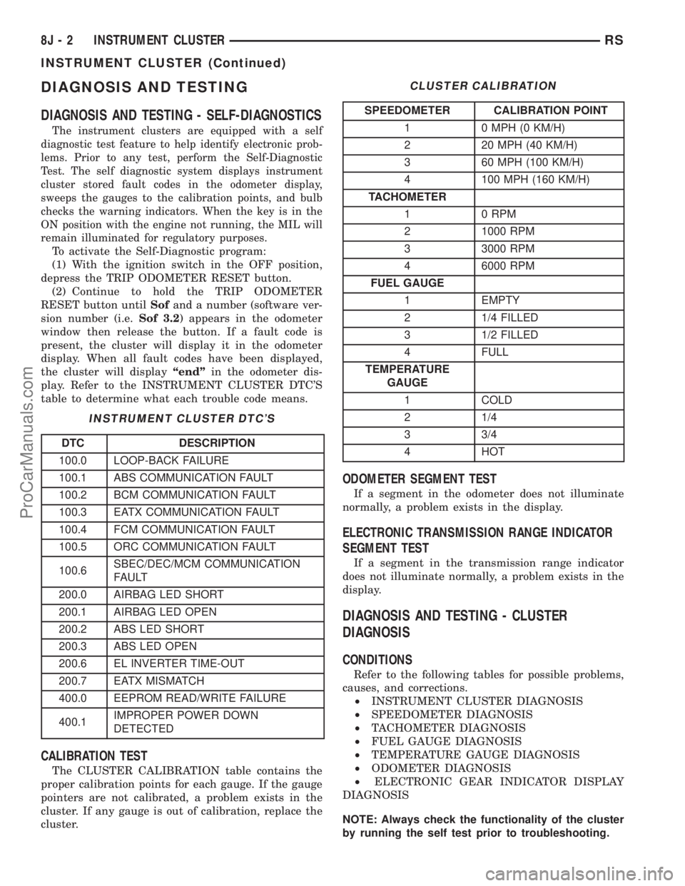
DIAGNOSIS AND TESTING - SELF-DIAGNOSTICS
The instrument clusters are equipped with a self
diagnostic test feature to help identify electronic prob-
lems. Prior to any test, perform the Self-Diagnostic
Test. The self diagnostic system displays instrument
cluster stored fault codes in the odometer display,
sweeps the gauges to the calibration points, and bulb
checks the warning indicators. When the key is in the
ON position with the engine not running, the MIL will
remain illuminated for regulatory purposes.
To activate the Self-Diagnostic program:
(1) With the ignition switch in the OFF position,
depress the TRIP ODOMETER RESET button.
(2) Continue to hold the TRIP ODOMETER
RESET button untilSofand a number (software ver-
sion number (i.e.Sof 3.2) appears in the odometer
window then release the button. If a fault code is
present, the cluster will display it in the odometer
display. When all fault codes have been displayed,
the cluster will displayªendºin the odometer dis-
play. Refer to the INSTRUMENT CLUSTER DTC'S
table to determine what each trouble code means.
INSTRUMENT CLUSTER DTC'S
DTC DESCRIPTION
100.0 LOOP-BACK FAILURE
100.1 ABS COMMUNICATION FAULT
100.2 BCM COMMUNICATION FAULT
100.3 EATX COMMUNICATION FAULT
100.4 FCM COMMUNICATION FAULT
100.5 ORC COMMUNICATION FAULT
100.6SBEC/DEC/MCM COMMUNICATION
FAULT
200.0 AIRBAG LED SHORT
200.1 AIRBAG LED OPEN
200.2 ABS LED SHORT
200.3 ABS LED OPEN
200.6 EL INVERTER TIME-OUT
200.7 EATX MISMATCH
400.0 EEPROM READ/WRITE FAILURE
400.1IMPROPER POWER DOWN
DETECTED
CALIBRATION TEST
The CLUSTER CALIBRATION table contains the
proper calibration points for each gauge. If the gauge
pointers are not calibrated, a problem exists in the
cluster. If any gauge is out of calibration, replace the
cluster.
CLUSTER CALIBRATION
SPEEDOMETER CALIBRATION POINT
1 0 MPH (0 KM/H)
2 20 MPH (40 KM/H)
3 60 MPH (100 KM/H)
4 100 MPH (160 KM/H)
TACHOMETER
1 0 RPM
2 1000 RPM
3 3000 RPM
4 6000 RPM
FUEL GAUGE
1 EMPTY
2 1/4 FILLED
3 1/2 FILLED
4 FULL
TEMPERATURE
GAUGE
1 COLD
2 1/4
3 3/4
4 HOT
ODOMETER SEGMENT TEST
If a segment in the odometer does not illuminate
normally, a problem exists in the display.
ELECTRONIC TRANSMISSION RANGE INDICATOR
SEGMENT TEST
If a segment in the transmission range indicator
does not illuminate normally, a problem exists in the
display.
DIAGNOSIS AND TESTING - CLUSTER
DIAGNOSIS
CONDITIONS
Refer to the following tables for possible problems,
causes, and corrections.
²INSTRUMENT CLUSTER DIAGNOSIS
²SPEEDOMETER DIAGNOSIS
²TACHOMETER DIAGNOSIS
²FUEL GAUGE DIAGNOSIS
²TEMPERATURE GAUGE DIAGNOSIS
²ODOMETER DIAGNOSIS
²ELECTRONIC GEAR INDICATOR DISPLAY
DIAGNOSIS
NOTE: Always check the functionality of the cluster
by running the self test prior to troubleshooting.
8J - 2 INSTRUMENT CLUSTERRS
INSTRUMENT CLUSTER (Continued)
ProCarManuals.com
Page 408 of 2177
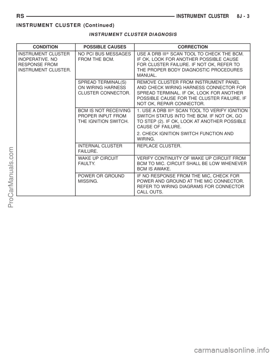
INSTRUMENT CLUSTER DIAGNOSIS
CONDITION POSSIBLE CAUSES CORRECTION
INSTRUMENT CLUSTER
INOPERATIVE. NO
RESPONSE FROM
INSTRUMENT CLUSTER.NO PCI BUS MESSAGES
FROM THE BCM.USE A DRB IIITSCAN TOOL TO CHECK THE BCM.
IF OK, LOOK FOR ANOTHER POSSIBLE CAUSE
FOR CLUSTER FAILURE. IF NOT OK, REFER TO
THE PROPER BODY DIAGNOSTIC PROCEDURES
MANUAL.
SPREAD TERMINAL(S)
ON WIRING HARNESS
CLUSTER CONNECTOR.REMOVE CLUSTER FROM INSTRUMENT PANEL
AND CHECK WIRING HARNESS CONNECTOR FOR
SPREAD TERMINAL. IF OK, LOOK FOR ANOTHER
POSSIBLE CAUSE FOR THE CLUSTER FAILURE. IF
NOT OK, REPAIR CONNECTOR.
BCM IS NOT RECEIVING
PROPER INPUT FROM
THE IGNITION SWITCH.1. USE A DRB IIITSCAN TOOL TO VERIFY IGNITION
SWITCH STATUS INTO THE BCM. IF NOT OK, GO
TO STEP (2). IF OK, LOOK AT ANOTHER POSSIBLE
CAUSE OF FAILURE.
2. CHECK IGNITION SWITCH FUNCTION AND
WIRING.
INTERNAL CLUSTER
FAILURE.REPLACE CLUSTER.
WAKE UP CIRCUIT
FAULTY.VERIFY CONTINUITY OF WAKE UP CIRCUIT FROM
BCM TO MIC. CIRCUIT SHALL BE LOW WHENEVER
BCM IS AWAKE.
POWER OR GROUND
MISSING.IF NO RESPONSE FROM THE MIC, CHECK FOR
POWER AND GROUND AT THE MIC CONNECTOR.
REFER TO WIRING DIAGRAMS FOR CONNECTOR
CALL OUTS.
RSINSTRUMENT CLUSTER8J-3
INSTRUMENT CLUSTER (Continued)
ProCarManuals.com
Page 409 of 2177
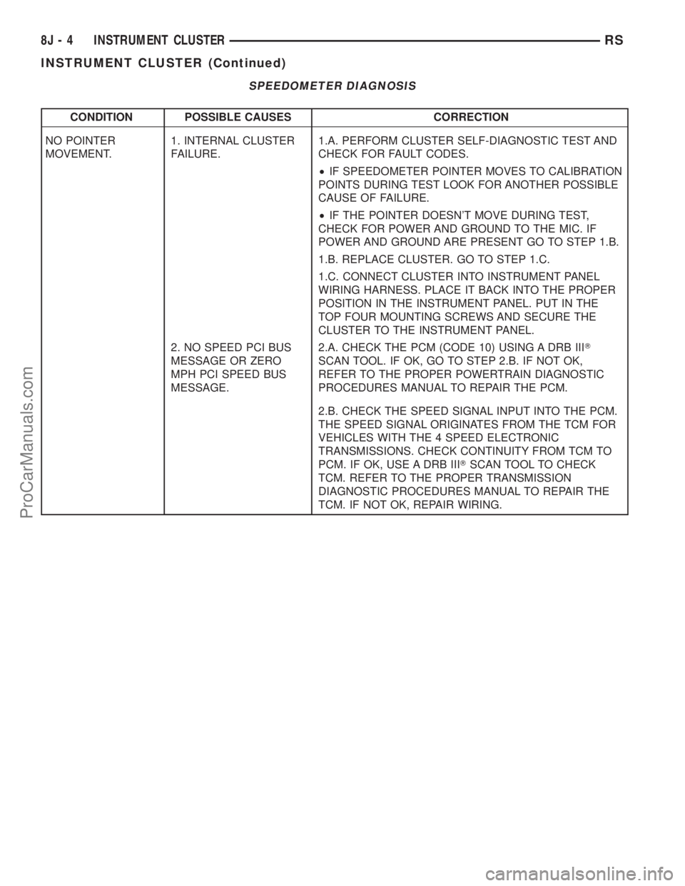
SPEEDOMETER DIAGNOSIS
CONDITION POSSIBLE CAUSES CORRECTION
NO POINTER
MOVEMENT.1. INTERNAL CLUSTER
FAILURE.1.A. PERFORM CLUSTER SELF-DIAGNOSTIC TEST AND
CHECK FOR FAULT CODES.
²IF SPEEDOMETER POINTER MOVES TO CALIBRATION
POINTS DURING TEST LOOK FOR ANOTHER POSSIBLE
CAUSE OF FAILURE.
²IF THE POINTER DOESN'T MOVE DURING TEST,
CHECK FOR POWER AND GROUND TO THE MIC. IF
POWER AND GROUND ARE PRESENT GO TO STEP 1.B.
1.B. REPLACE CLUSTER. GO TO STEP 1.C.
1.C. CONNECT CLUSTER INTO INSTRUMENT PANEL
WIRING HARNESS. PLACE IT BACK INTO THE PROPER
POSITION IN THE INSTRUMENT PANEL. PUT IN THE
TOP FOUR MOUNTING SCREWS AND SECURE THE
CLUSTER TO THE INSTRUMENT PANEL.
2. NO SPEED PCI BUS
MESSAGE OR ZERO
MPH PCI SPEED BUS
MESSAGE.2.A. CHECK THE PCM (CODE 10) USING A DRB IIIT
SCAN TOOL. IF OK, GO TO STEP 2.B. IF NOT OK,
REFER TO THE PROPER POWERTRAIN DIAGNOSTIC
PROCEDURES MANUAL TO REPAIR THE PCM.
2.B. CHECK THE SPEED SIGNAL INPUT INTO THE PCM.
THE SPEED SIGNAL ORIGINATES FROM THE TCM FOR
VEHICLES WITH THE 4 SPEED ELECTRONIC
TRANSMISSIONS. CHECK CONTINUITY FROM TCM TO
PCM. IF OK, USE A DRB IIITSCAN TOOL TO CHECK
TCM. REFER TO THE PROPER TRANSMISSION
DIAGNOSTIC PROCEDURES MANUAL TO REPAIR THE
TCM. IF NOT OK, REPAIR WIRING.
8J - 4 INSTRUMENT CLUSTERRS
INSTRUMENT CLUSTER (Continued)
ProCarManuals.com
Page 410 of 2177
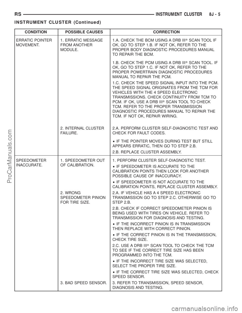
CONDITION POSSIBLE CAUSES CORRECTION
ERRATIC POINTER
MOVEMENT.1. ERRATIC MESSAGE
FROM ANOTHER
MODULE.1.A. CHECK THE BCM USING A DRB IIITSCAN TOOL IF
OK, GO TO STEP 1.B. IF NOT OK, REFER TO THE
PROPER BODY DIAGNOSTIC PROCEDURES MANUAL
TO REPAIR THE BCM.
1.B. CHECK THE PCM USING A DRB IIITSCAN TOOL. IF
OK, GO TO STEP 1.C. IF NOT OK, REFER TO THE
PROPER POWERTRAIN DIAGNOSTIC PROCEDURES
MANUAL TO REPAIR THE PCM.
1.C. CHECK THE SPEED SIGNAL INPUT INTO THE PCM.
THE SPEED SIGNAL ORIGINATES FROM THE TCM FOR
VEHICLES WITH THE 4 SPEED ELECTRONIC
TRANSMISSIONS. CHECK CONTINUITY FROM TCM TO
PCM. IF OK, USE A DRB IIITSCAN TOOL TO CHECK
TCM. REFER TO THE PROPER TRANSMISSION
DIAGNOSTIC PROCEDURES MANUAL TO REPAIR THE
TCM. IF NOT OK, REPAIR WIRING.
2. INTERNAL CLUSTER
FAILURE.2.A. PERFORM CLUSTER SELF-DIAGNOSTIC TEST AND
CHECK FOR FAULT CODES.
²IF THE POINTER MOVES DURING TEST BUT STILL
APPEARS ERRATIC, THEN GO TO STEP 2.B.
2.B. REPLACE CLUSTER ASSEMBLY.
SPEEDOMETER
INACCURATE.1. SPEEDOMETER OUT
OF CALIBRATION.1. PERFORM CLUSTER SELF-DIAGNOSTIC TEST.
²IF SPEEDOMETER IS ACCURATE TO THE
CALIBRATION POINTS THEN LOOK FOR ANOTHER
POSSIBLE CAUSE OF INACCURACY.
²IF SPEEDOMETER IS NOT ACCURATE TO THE
CALIBRATION POINTS, REPLACE CLUSTER ASSEMBLY.
2. WRONG
SPEEDOMETER PINION
FOR TIRE SIZE.2.A. IF VEHICLE HAS A 4 SPEED ELECTRONIC
TRANSMISSION GO TO STEP 2.C. OTHERWISE GO TO
STEP 2.B.
2.B. CHECK IF CORRECT SPEEDOMETER PINION IS
BEING USED WITH TIRES ON VEHICLE. REFER TO
TRANSMISSION FOR DIAGNOSIS AND TESTING.
²IF THE INCORRECT PINION IS IN TRANSMISSION
THEN REPLACE WITH CORRECT PINION.
²IF THE CORRECT PINION IS IN THE TRANSMISSION,
CHECK TIRE SIZE.
2.C. USE A DRB IIITSCAN TOOL TO CHECK THE TCM
TO SEE IF THE CORRECT TIRE SIZE HAS BEEN
PROGRAMMED INTO THE TCM.
²IF THE INCORRECT TIRE SIZE WAS SELECTED,
SELECT THE PROPER TIRE SIZE.
²IF THE CORRECT TIRE SIZE WAS SELECTED, CHECK
SPEED SENSOR.
3. BAD SPEED SENSOR. 3. REFER TO TRANSMISSION, SPEED SENSOR,
DIAGNOSIS AND TESTING.
RSINSTRUMENT CLUSTER8J-5
INSTRUMENT CLUSTER (Continued)
ProCarManuals.com