maintenance schedule DODGE TRUCK 1993 Service User Guide
[x] Cancel search | Manufacturer: DODGE, Model Year: 1993, Model line: TRUCK, Model: DODGE TRUCK 1993Pages: 1502, PDF Size: 80.97 MB
Page 40 of 1502
•
LUBRICATION
AND
MAINTENANCE
0 - 21 ROUTINE INSPECTION
It is recommended that the drive belt(s) be rou
tinely inspected for cracks, fraying and excessive
wear. Replace as necessary.
EXHAUST SYSTEM
An exhaust system must be properly aligned to
prevent stress, leakage, and vehicle body contact.
MAINTENANCE SCHEDULE Inspect the exhaust system at the interval specified
in maintenance schedule.
INSPECTION Inspect for cracked or loose joints, corrosion dam
age,
and worn or broken hangers. Replace all compo
nents that are damaged. Do not attempt repair. Also,
inspect for the following conditions and correct as
necessary:
• Exhaust system leaks, misalignment • Contact with body panels or the frame
• Catalytic converter bulging or excessive heat dam
age
CAUTION:
A
catalytic converter
will
become
con
taminated
if
leaded gasoline
is
burned
in the en
gine.
If
this
occurs,
the
complete converter must
be
replaced.
AIR-CONDITIONER COMPRESSOR LUBRICANT
AND
REFRIGERANT
The lubricant level in the compressor should be
checked if there are indications that oil was lost.
Loss of lubricating oil usually accompanies a loss of
refrigerant. The presence of bubbles in sight glass in dicates that loss of refrigerant has occurred. For additional information involving the A/C sys
tem, refer to Group 24—Heater And Air Condition ing.
Page 43 of 1502
0
- 24
LUBRICATION
AND
MAINTENANCE
•
CAUTION:
Do not
overfill
the
transmission.
(9) Adjust
the
level
of the ATF
accordingly.
It
is
important
to use the
correct fluid
in an
automatic transmission. MOPAR®ATF PLUS
(ATF Type
7176)
should
be
used. Dexron®
II
ATF
can be
used
if the
recommended fluid
is not
available,
(10) Insert
the
dipstick into
the
tube.
DRAIN, FILTER CHANGE, BAND ADJUSTMENT AND REFILL
The chart below lists
the
intervals
at
which
the
transmission should
be
serviced. Also, refer
to the
Fluid Capacities chart
for
fill capacity.
AUTOMATIC TRANSMISSION SERVICE
IN-
TERVALS
Normal
Usage
Light
Duty
Cycle
60 000
km
37,500
miles
Heavy
Duty
Cycle
38
000 km 24,000
miles
Severe
Usage
19 000 km 12,000
miles
J9100-19
It
is
very important
to use the
correct fluid
in
an automatic transmission. MOPAR®ATF PLUS
(ATF Type
7176)
should
be
used.
An
equivalent
Dexron®
II ATF
could
be
used only
if the
recom
mended fluid
is not
available.
The torque converter does
not
have
a
drain plug.
No attempt should
be
made
to
drain
the
converter.
Refer
to
Group
21
—Transmissions
for
transmission
drain
and
refill procedures.
TRANSFER
CASE
(4WD
VEHICLES)
INSPECTION The NP205
and
NP241 transfer cases fluid level
should
be
checked whenever maintenance
is
neces
sary under
the
vehicle.
FLUID
LEVEL
The vehicle must
be
level when
the
fluid level
is checked.
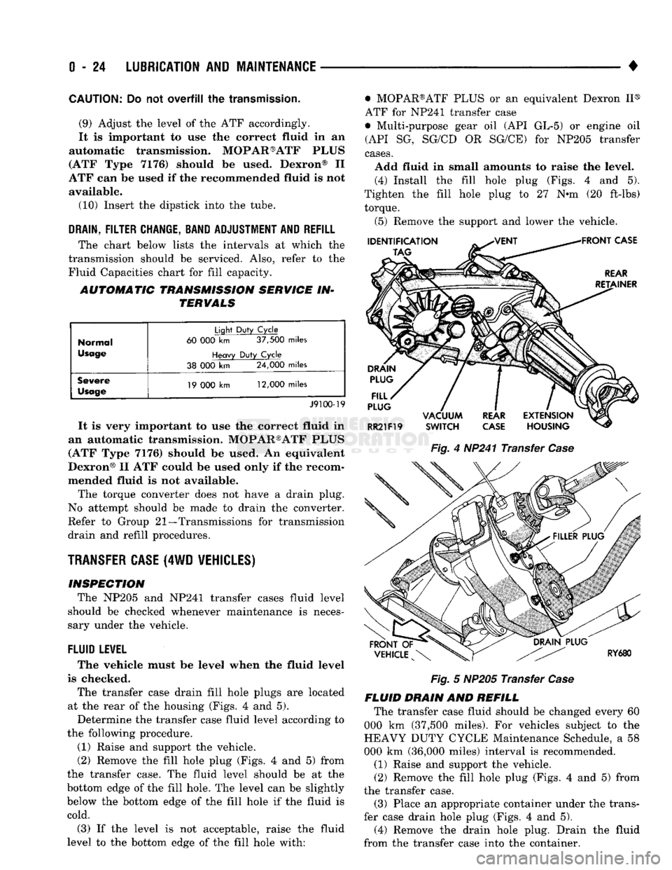
The transfer case drain fill hole plugs
are
located
at
the
rear
of the
housing (Figs.
4 and 5).
Determine
the
transfer case fluid level according
to
the following procedure.
(1) Raise
and
support
the
vehicle.
(2) Remove
the
fill hole plug (Figs.
4 and 5)
from
the transfer case.
The
fluid level should
be at the
bottom edge
of the
fill hole.
The
level
can be
slightly
below
the
bottom edge
of the
fill hole
if the
fluid
is
cold.
(3)
If the
level
is not
acceptable, raise
the
fluid
level
to the
bottom edge
of the
fill hole with: • MOPAR®ATF PLUS
or an
equivalent Dexron
II®
ATF
for
NP241 transfer case
• Multi-purpose gear
oil (API GL-5) or
engine
oil
(API
SG,
SG/CD
OR
SG/CE)
for
NP205 transfer
cases.
Add fluid
in
small amounts
to
raise
the
level. (4) Install
the
fill hole plug (Figs.
4 and 5).
Tighten
the
fill hole plug
to 27 N-m (20
ft-lbs) torque.
(5) Remove
the
support
and
lower
the
vehicle.
Fig.
4
HP241 Transfer
Case
Fig.
5
NP205 Transfer
Case
FLUID DRAIN
AND
REFILL The transfer case fluid should
be
changed every
60
000
km
(37,500 miles).
For
vehicles subject
to the
HEAVY DUTY CYCLE Maintenance Schedule,
a 58
000
km
(36,000 miles) interval
is
recommended.
(1) Raise
and
support
the
vehicle.
(2) Remove
the
fill hole plug (Figs.
4 and 5)
from
the transfer case. (3) Place
an
appropriate container under
the
trans
fer case drain hole plug (Figs.
4 and 5).
(4) Remove
the
drain hole plug. Drain
the
fluid
from
the
transfer case into
the
container.
Page 45 of 1502
0
- 26
LUBRICATION
AND
MAINTENANCE
•
"PRESS-IN"
TYPE FILLER PLUG
RK43t
Fig.
8
Rear Axle Fill Plug Location—Typical Fig.
9
Front Axle (4
WD)
Fill Plug Location
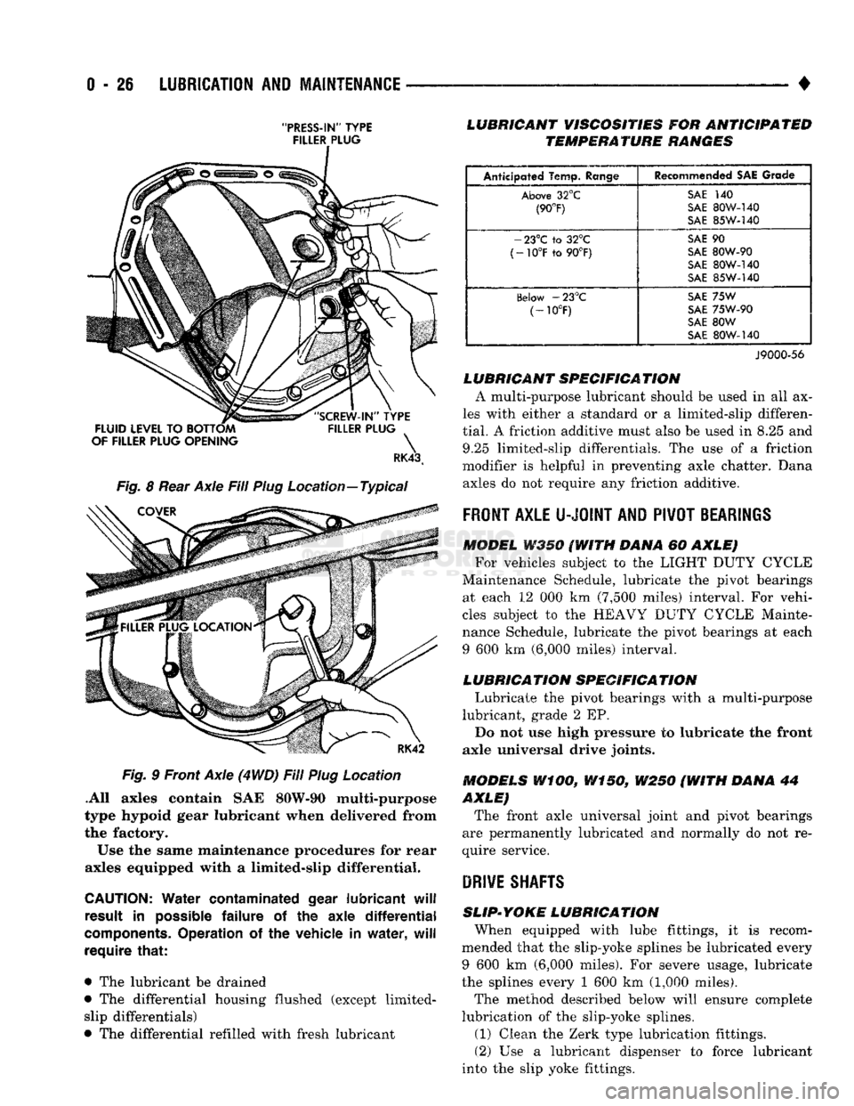
.All axles contain
SAE
80W-90 multi-purpose
type hypoid gear lubricant when delivered from
the factory.
Use
the
same maintenance procedures
for
rear
axles equipped with
a
limited-slip differential.
CAUTION:
Water
contaminated
gear
lubricant
will
result
in
possible
failure
of the
axle
differential
components.
Operation
of the
vehicle
in
water,
will
require
that:
•
The
lubricant
be
drained
•
The
differential housing flushed (except limited- slip differentials)
•
The
differential refilled with fresh lubricant
LUBRICANT
VISCOSITIES
FOR
ANTICIPATED
TEMPERATURE
RANGES
Anticipated Temp.
Range
Recommended
SAE
Grade
Above
32°C
SAi
140
(90°F)
SAE
SOW-140
(90°F)
S\E
85W-140
-
23°C to 32°C
SAE
90
(-10°F
to 90°F)
SAE
80W-90
(-10°F
to 90°F)
SAE
80W-140
oAE
85W-140
(ielow
-23°C
SAE
75W
(-10°F)
SAE
75W-90
(-10°F)
SAE
80W
SAE
80W-I40
J9000-56
LUBRICANT
SPECIFICA
TION
A multi-purpose lubricant should
be
used
in all ax
les with either
a
standard
or a
limited-slip differen
tial.
A
friction additive must also
be
used
in 8.25 and
9.25 limited-slip differentials.
The use of a
friction
modifier
is
helpful
in
preventing axle chatter. Dana axles
do not
require
any
friction additive.
FRONT
AXLE
U-JOINT
AND
PIVOT
BEARINGS
MODEL
W350 (WITH
DANA
60
AXLE) For vehicles subject
to the
LIGHT DUTY CYCLE
Maintenance Schedule, lubricate
the
pivot bearings at each
12 000 km
(7,500 miles) interval.
For
vehi
cles subject
to the
HEAVY DUTY CYCLE Mainte
nance Schedule, lubricate
the
pivot bearings
at
each
9
600 km
(6,000 miles) interval.
LUBRICATION
SPECIFICATION
Lubricate
the
pivot bearings with
a
multi-purpose
lubricant, grade
2 EP.
Do
not use
high pressure
to
lubricate
the
front
axle universal drive joints.
MODELS
WiOO,
W150,
W250 (WITH
DANA
44
AXLE)
The front axle universal joint
and
pivot bearings
are permanently lubricated
and
normally
do not re
quire service.
DRIVE
SHAFTS
SLIP-YOKE
LUBRICATION
When equipped with lube fittings,
it is
recom
mended that
the
slip-yoke splines
be
lubricated every
9
600 km
(6,000 miles).
For
severe usage, lubricate
the splines every
1 600 km
(1,000 miles).
The method described below will ensure complete
lubrication
of the
slip-yoke splines.
(1)
Clean
the
Zerk type lubrication fittings.
(2)
Use a
lubricant dispenser
to
force lubricant
into
the
slip yoke fittings.
Page 47 of 1502
0
- 28
LUBRICATION
AND
MAINTENANCE
•
CHASSIS AND BODY
page
Body
Component Mechanisms
32
Front
Suspension
Ball
Joints
28
Front
Wheel Bearings
29
Headlamps
32
Lower
and
Upper Suspension
Arm
Bushings
.... 30
Manual
Steering Gear
28
STEERING
LINKAGE
INSPECTION When
a
vehicle
is
raised
for
maintenance under
the vehicle,
all
steering components should
be
checked.
LUBRICATION SCHEDULE The steering linkage
is
lubricated with
a
chassis
lubricant. However,
it is
recommended that
the
link
age
be
inspected
and
lubricated after each:
•
24 000 km
(15,000 miles) interval
or
every
6
months,
for 2WD
vehicles subject
to the
LIGHT
DUTY CYCLE Maintenance Schedule
•
9 600 km
(6,000 miles) interval
or
every
6
months,
for
2WD
vehicles subject
to the
HEAVY DUTY
CY
CLE Maintenance Schedule
•
12 000 km
(7,500 miles) interval
or
every
6
months,
for 4WD
vehicles subject
to the
LIGHT DUTY CYCLE Maintenance Schedule
•
9 600 km
(6,000 miles) interval
or
every
6
months,
for
4WD
vehicles subject
to the
HEAVY DUTY
CY
CLE Maintenance Schedule.
LUBRICATION (1) Inspect
the
steering linkage
for
looseness
and
excessive wear. (2) Replace,
all
ruptured seals
and
damaged steer
ing linkage components. Damaged seals should
be re
placed
to
prevent leakage
and
contamination
of the
lubricant.
CAUTION:
Use
care
to
prevent lubricant from
con
tacting
the
brake rotors.
(3) Lubricate
the
steering linkage:
• Clean
the
Zerk type lubrication fittings
on the tie-
rod
and
center link ball-stud ends
• Lubricate
the
ball studs with MOPAR®Multi-Mile- age Lubricant
• Wipe
the
excess lubricant from
the
exterior sur
faces
of the
ball joints
page
Power
Brake System
30
Power
Steering System
. . 29
Rear
Wheel Bearings
30
Speedometer Cable
33
Steering Linkage
28
Tires
32
FRONT
SUSPENSION
BALL JOINTS
INSPECTION When
a
vehicle
is
raised
for
lubrication/general
maintenance,
the
ball joints should
be
inspected.
LUBRICATION SCHEDULE The front suspension ball joints
are
lubricated dur
ing manufacture with
a
long-life chassis lubricant.
However,
it is
recommended that
the
ball joints
be
inspected
and the
studs lubricated:
•
At
each
36 000 km
(22,500 miles) interval
or
every
2 years,
for
vehicles subject
to the
LIGHT DUTY
CY
CLE Maintenance Schedule
•
At
each
9 600 km
(6,000 miles) interval
or
every
2
years,
for
vehicles subject
to the
HEAVY DUTY
CY
CLE Maintenance Schedule.
4WD vehicles that
are
frequently driven
off-
road should
be
lubricated
at
every engine
oil
change.
LUBRICATION (1) Inspect
the
front suspension. Examine
the
ball
studs
for
looseness
and
excessive wear. (2) Replace
all
torn ball-stud seals
and
damaged
ball joints. Damaged seals should
be
replaced
to
pre vent leakage
and
contamination.
CAUTION:
Use
care
to
prevent lubricant from
con
tacting
the
brake rotors.
(3) Lubricate
the
ball studs:
• Clean
the
Zerk type lubrication fittings
on the
ball-stud ends
• Lubricate
the
ball studs with MOPAR®Multi-Mile-age Lubricant
• Wipe
the
excess lubricant from
the
exterior sur
faces
of the
ball joints
MANUAL
STEERING
GEAR
LUBRICATION Manual steering gears
are
permanently lubricated
during manufacture. Periodic lubrication
is not
nec
essary.
Page 48 of 1502
•
LUBRICATION
AND
MAINTENANCE
0 - 29
POWER STEERING SYSTEM
SERVICE SCHEDULE
FLUID
LEWEL
WARNING.
THE
POWER
STEERING
FLUID LEVEL
SHOULD
ALWAYS
BE
CHECKED
WITH THE EN
GINE
OFF TO
PREVENT
PERSONAL
INJURY.
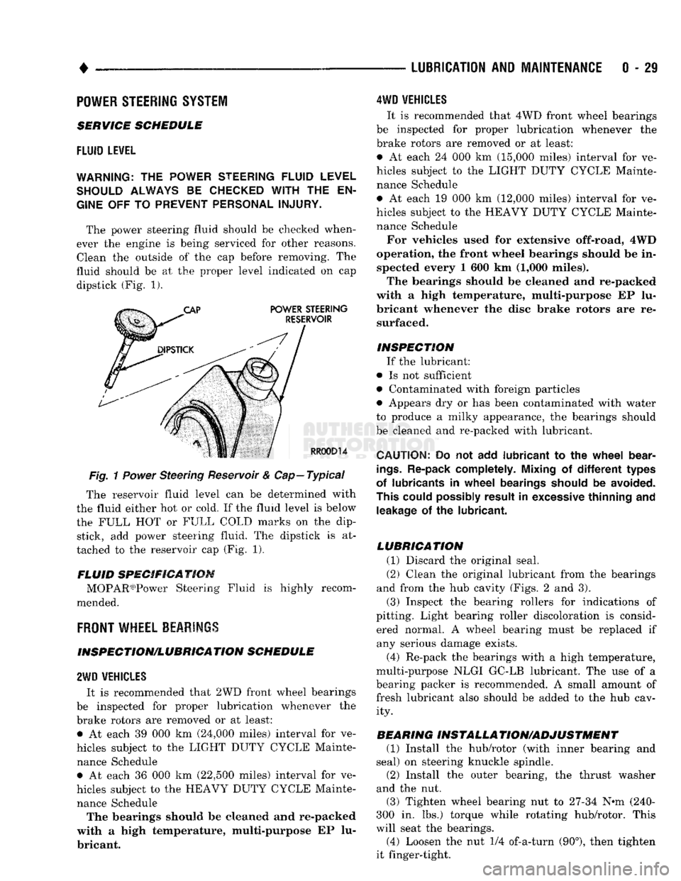
The power steering fluid should be checked when
ever the engine is being serviced for other reasons. Clean the outside of the cap before removing. The
fluid should be at the proper level indicated on cap dipstick (Fig. 1).
Fig.
1
Power
Steering Reservoir & Cap—Typical
The reservoir fluid level can be determined with
the fluid either hot or cold. If the fluid level is below
the FULL HOT or FULL COLD marks on the dip stick, add power steering fluid. The dipstick is at
tached to the reservoir cap (Fig. 1).
FLUID SPECIFICATION MOPAR03)Power Steering Fluid is highly recom
mended.
FRONT
WHEEL BEARINGS
INSPECTION/LUBRICATION SCHEDULE
2WD
VEHICLES
It is recommended that 2WD front wheel bearings
be inspected for proper lubrication whenever the
brake rotors are removed or at least: • At each 39 000 km (24,000 miles) interval for ve
hicles subject to the LIGHT DUTY CYCLE Mainte nance Schedule • At each 36 000 km (22,500 miles) interval for ve
hicles subject to the HEAVY DUTY CYCLE Mainte nance Schedule The bearings should be cleaned and re-packed
with a high temperature, multi-purpose EP lu
bricant.
4WD
VEHICLES
It is recommended that 4WD front wheel bearings
be inspected for proper lubrication whenever the
brake rotors are removed or at least:
• At each 24 000 km (15,000 miles) interval for ve
hicles subject to the LIGHT DUTY CYCLE Mainte nance Schedule
• At each 19 000 km (12,000 miles) interval for ve
hicles subject to the HEAVY DUTY CYCLE Mainte nance Schedule
For vehicles used for extensive off-road, 4WD
operation, the front wheel bearings should be in spected every 1 600 km (1,000 miles).
The bearings should be cleaned and re-packed
with a high temperature, multi-purpose EP lu
bricant whenever the disc brake rotors are re surfaced.
INSPECTION If the lubricant:
• Is not sufficient
• Contaminated with foreign particles
• Appears dry or has been contaminated with water
to produce a milky appearance, the bearings should
be cleaned and re-packed with lubricant.
CAUTION:
Do not add
lubricant
to the
wheel
bear
ings.
Re-pack completely. Mixing
of
different
types
of lubricants
in
wheel
bearings should
be
avoided.
This could possibly result
in
excessive thinning
and
leakage
of the
lubricant.
LUBRICATION (1) Discard the original seal.
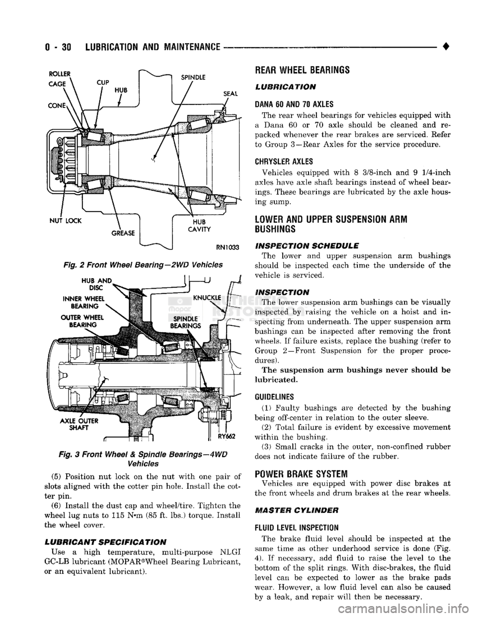
(2) Clean the original lubricant from the bearings
and from the hub cavity (Figs. 2 and 3).
(3) Inspect the bearing rollers for indications of
pitting. Light bearing roller discoloration is consid ered normal. A wheel bearing must be replaced if any serious damage exists.
(4) Re-pack the bearings with a high temperature,
multi-purpose NLGI GC-LB lubricant. The use of a
bearing packer is recommended. A small amount of fresh lubricant also should be added to the hub cav ity.
BEARING INSTALLA TION/ADJUSTMENT (1) Install the hub/rotor (with inner bearing and
seal) on steering knuckle spindle.
(2) Install the outer bearing, the thrust washer
and the nut.
(3) Tighten wheel bearing nut to 27-34 N^m (240-
300 in. lbs.) torque while rotating hub/rotor. This
will seat the bearings.
(4) Loosen the nut 1/4 of-a-turn (90°), then tighten
it finger-tight.
Page 49 of 1502
0 - 30
LUBRICATION
AND
MAINTENANCE
— - •
Fig.
2 Front
Wheel
Bearing—2WD Vehicles
Fig.
3 Front
Wheel
&
Spindle
Bearings—4WD
Vehicles
(5) Position nut lock on the nut with one pair of
slots aligned with the cotter pin hole. Install the cot
ter pin.
(6) Install the dust cap and wheel/tire. Tighten the
wheel lug nuts to 115 N*m (85 ft. lbs.) torque. Install
the wheel cover.
LUBRICANT SPECIFICATION
Use a high temperature, multi-purpose NLGI
GC-LB lubricant (MOPAR®Wheel Bearing Lubricant,
or an equivalent lubricant).
REAR
WHEEL BEARINGS
LUBRICATION
DANA
60
AND
70
AXLES
The rear wheel bearings for vehicles equipped with
a Dana 60 or 70 axle should be cleaned and re
packed whenever the rear brakes are serviced. Refer
to Group 3—Rear Axles for the service procedure.
CHRYSLER
AXLES
, Vehicles equipped with 8 3/8-inch and 9
1/4-inch
axles have axle shaft bearings instead of wheel bear
ings.
These bearings are lubricated by the axle hous
ing sump.
LOWER
AND UPPER
SUSPENSION
ARM
BUSHINGS
INSPECTION
SCHEDULE
The lower and upper suspension arm bushings
should be inspected each time the underside of the
vehicle is serviced.
INSPECTION
The lower suspension arm bushings can be visually
inspected by raising the vehicle on a hoist and in specting from underneath. The upper suspension arm
bushings can be inspected after removing the front wheels. If failure exists, replace the bushing (refer to Group 2—Front Suspension for the proper proce
dures).
The suspension arm bushings never should be
lubricated.
GUIDELINES
(1) Faulty bushings are detected by the bushing
being off-center in relation to the outer sleeve.
(2) Total failure is evident by excessive movement
within the bushing.
(3)
Small cracks in the outer, non-confined rubber
does not indicate failure of the rubber. '
POWER BRAKE SYSTEM
Vehicles are equipped with power disc brakes at
the front wheels and drum brakes at the rear wheels.
MASTER CYLINDER
FLUID
LEVEL INSPECTION
The brake fluid level should be inspected at the
same time as other underhood service is done (Fig.
4).
If necessary, add fluid to raise the level to the
bottom of the split rings. With disc-brakes, the fluid level can be expected to lower as the brake pads
wear. However, a low fluid level can also be caused
by a leak, and repair will then be necessary.
Page 51 of 1502
0
- 32
LUBRICATION
AND
MAINTENANCE
•
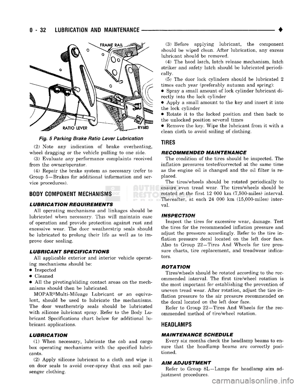
Fig.
5 Parking Brake Ratio Lever Lubrication (2) Note any indication of brake overheating,
wheel dragging or the vehicle pulling to one side.
(3) Evaluate any performance complaints received
from the owner/operator. (4) Repair the brake system as necessary (refer to
Group 5—Brakes for additional information and ser
vice procedures).
BODY
COMPONENT
MECHANISMS
LUBRICATION REQUIREMENTS
All operating mechanisms and linkages should be
lubricated when necessary. This will maintain ease of operation and provide protection against rust and
excessive wear. The door weatherstrip seals should
be lubricated to prolong their life as well as to im prove door sealing.
LUBRICANT SPECIFICATIONS
All applicable exterior and interior vehicle operat
ing mechanisms should be:
• Inspected • Cleaned
• All the pivoting/sliding contact areas on the mech anisms should then be lubricated.
MOPAR®Multi-Mileage Lubricant or an equiva
lent, should be used to lubricate the mechanisms.
The door weatherstrip seals should be lubricated
with silicone lubricant spray. Refer to the Body Lu
bricant Specifications chart below for additional lu
bricant applications.
LUBRICATION
(1) When necessary, lubricate the cab and cargo
box operating mechanisms with the specified lubri
cants.
(2) Apply silicone lubricant to a cloth and wipe it
on door seals to avoid over-spray that can soil pas
senger clothing. (3) Before applying lubricant, the component
should be wiped clean. After lubrication, any excess
lubricant should be removed.
(4) The hood latch, latch release mechanism, latch
striker and safety latch should be lubricated periodi
cally.
(5) The door lock cylinders should be lubricated 2
times each year (preferably autumn and spring): • Spray a small amount of lock cylinder lubricant di
rectly into the lock cylinder
• Apply a small amount to the key and insert it into
the lock cylinder • Rotate it to the locked position and then back to
the unlocked position several times
• Remove the key. Wipe the lubricant from it with a
clean cloth to avoid soiling of clothing.
TIRES
RECOMMENDED MAINTENANCE
The condition of the tires should be inspected. The
inflation pressures tested/corrected at the same time as the engine oil is changed and the oil filter is re
placed.
The tires/wheels should be rotated periodically to
ensure even tread wear. The tires/wheels should be
rotated at the first 12 000 km (7,500-miles) interval.
Thereafter, at each 24 000 km (15,000-miles) inter
val.
INSPECTION
Inspect the tires for excessive wear, damage. Test
the tires for the recommended inflation pressure and adjust the pressure accordingly. Refer to the tire in
flation pressure decal located on the left door face. Also to Group 22—Tires And Wheels for tire pressure charts, tire replacement, and treadwear indica
tors.
ROTATION
Tires/wheels should be rotated according to the rec
ommended interval. The first tire/wheel rotation is
the most important for establishing the prevention of uneven tread wear. After rotation, adjust the tire in
flation pressure to the air pressure recommended on
the decal located on the left door face.
Refer to Group 22—Tires And Wheels for the rec
ommended method of tire/wheel rotation.
HEADLAMPS
MAINTENANCE SCHEDULE
Every six months check the headlamp beams to en
sure that the headlamp beams are correctly posi
tioned.
AIM
ADJUSTMENT
Refer to Group 8L—Lamps for headlamp aim ad
justment procedures.
Page 352 of 1502
•
IGNITION
SYSTEMS
8D
- 1
CONTENTS
page page
COMPONENT IDENTIFICATION/SYSTEM DIAGNOSTICS/SERVICE PROCEDURES
7
OPERATION
1
IGNITION SWITCH
25
COMPONENT REMOVAL/INSTALLATION
..... 18
SPECIFICATIONS
28
COMPONENT
IDENTIFICATION/SYSTEM OPERATION
INDEX
page
Automatic
Shut Down (ASD) Relay
1
Camshaft Position Sensor
2
Crankshaft Position Sensor
2
Distributors
3
Engine Coolant
Temperature
Sensor
...........
4
General
Information
1
page
Ignition
Coil
3
Intake
Manifold Charge
Air
Temperature
Sensor
. . 4
Manifold Absolute Pressure (MAP) Sensor
4
Powertrain
Control
Module (PCM)
. 5
Throttle
Position Sensor
5
GENERAL
INFORMATION
Throughout this group, references
are
made
to
par
ticular vehicle models
by
alphabetical designation
or
by
the
particular vehicle nameplate.
A
chart showing a breakdown
of
alphabetical designations
is
included
in
the
Introduction group
at the
beginning
of
this
manual. 5.9L
gas
powered engines will
be
referred
to as ei
ther: LDC (Light Duty Cycle),
or
HDC (Heavy Duty Cycle). This section
of the
group, Component Identifica
tion/System Operation, will discuss ignition system operation
and
will identify ignition system compo
nents.
For diagnostic procedures
and
adjustments, refer
to
the Diagnostics/Service Procedures section
of
this
group.
For removal
and
installation
of
ignition system
components, refer
to the
Component Removal/Instal
lation section
of
this group. For other useful information, refer
to
On-Board
Di
agnostics
in the
General Diagnosis sections
of
Group
14,
Fuel System
in
this manual. For operation
of the DRB II
Diagnostic Scan Tool,
refer
to the
appropriate Powertrain Diagnostic Proce
dures service manual.
An Ignition specifications section
is
included
at the
end
of
this group.
A
general Maintenance Schedule (mileage intervals)
for
ignition related items
can be
found
in
Group
0,
Lubrication and Maintenance. This
schedule
can
also
be
found
in the
Owners Manual.
IGNITION
SYSTEMS
The ignition systems used
on all
engines
are
basi
cally identical. Similarities
and
differences between
the systems will
be
discussed.
A sequential multi-port fuel injection system
is
used
on all gas
powered engines.
The ignition system
is
controlled
by the
powertrain
control module (PCM)
on all
engines.
The
PCM
was
formerly referred
to as the
SBEC
or
engine control ler.
The ignition system consists
of:
• Spark Plugs
• Ignition Coil
• Secondary Ignition Cables
• Ignition distributor. Contains rotor
and
camshaft
position sensor • Powertrain Control Module (PCM)
• Crankshaft Position Sensor
AUTOMATIC SHUT DOWN (ASD) RELAY
The automatic shut down (ASD) relay
is
located
in
the engine compartment (Fig.
1). As one of its
func
tions,
the ASD
relay will supply battery voltage
to
the ignition coil.
The
ground circuit
for the
ASD
re
lay
is
controlled
by the
powertrain control module (PCM).
The PCM
regulates
ASD
relay operation
by
switching
the
ground circuit on-and-off.
IGNITION
SYSTEMS
Page 384 of 1502
•
INSTRUMENT PANEL
AND
GAUGES
8E - 3
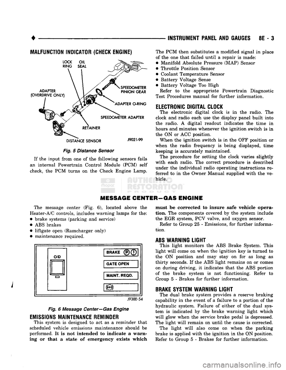
MALFUNCTION INDICATOR (CHECK ENGINE)
Fig.
5
Distance Sensor
If
the
input from
one of the
following sensors fails
an internal Powertrain Control Module
(PCM)
self
check,
the PCM
turns
on the
Check Engine Lamp. The
PCM
then substitutes
a
modified signal
in
place
of
the one
that failed until
a
repair
is
made:
• Manifold Absolute Pressure (MAP) Sensor
• Throttle Position Sensor
• Coolant Temperature Sensor
• Battery Voltage Sense
• Battery Voltage
Too
High
Refer
to the
appropriate Powertrain Diagnostic
Test Procedures manual
for
further information.
ELECTRONIC DIGITAL CLOCK
The electronic digital clock
is in the
radio.
The
clock
and
radio each
use the
display panel built into
the radio.
A
digital readout indicates
the
time
in
hours
and
minutes whenever
the
ignition switch
is in
the
ON or ACC
position. When
the
ignition switch
is in the OFF
position
or
when
the
radio frequency
is
being displayed, time keeping
is
accurately maintained. The procedure
for
setting
the
clock varies slightly
with each radio.
The
correct procedure
is
described under
the
individual radio operating instructions
re
ferred
to in the
Owner Manual supplied with
the ve
hicle.
MESSAGE CENTER—GAS ENGINE
The message center
(Fig. 6),
located above
the
Heater-A/C controls, includes warning lamps
for the:
• brake systems (parking
and
service)
•
ABS
brakes • liftgate open (Ramcharger only)
• maintenance required.
O/D
BRAKE
(P)(7
GATE OPEN
MAINT
REQD.
J938E-54
Fig.
6
Message Center—Gas Engine
EMISSIONS
MAINTENANCE REMINDER
This system
is
designed
to act as a
reminder that
scheduled vehicle emissions maintenance should
be
performed.
It is not
intended
to
indicate
a
warn
ing
or
that
a
state
of
emergency exists which must
be
corrected
to
insure safe vehicle opera
tion.
The
components covered
by the
system include
the
EGR
system,
PCV
valve,
and
oxygen sensor. Refer
to
Group
25 -
Emissions,
for
further informa
tion.
ABS
WARNING
LIGHT
This light monitors
the ABS
Brake System. This
light will come
on
when
the
ignition
key is
turned
to
the
ON
position
and may
stay
on for as
long
as
thirty seconds.
If the ABS
light remains
on or
comes on during driving,
it
indicates that
the ABS
portion
of
the
brake system
is not
functioning. Refer
to
Group
5 -
Brakes
for
further information.
BRAKE
SYSTEM WARNING
LIGHT
The dual brake system provides
a
reserve braking
capability
in the
event
of a
failure
to a
portion
of the
hydraulic system. Failure
of
either
of the
dual sys
tem
is
indicated
by the
brake warning light which
will glow when
the
service brake pedal
is
depressed.
The light will remain
on
until
the
cause
is
corrected. The light will also come
on
when
the
parking
brake
is
applied with
the
ignition
in the ON
position.
Refer
to
Group
5 -
Brakes
for
further information.
Page 904 of 1502
•
FUEL SYSTEM
14-85 to pass through it, but prevents moisture (water)
from doing so. Moisture collects at the bottom of the
separator filter.
WARNING:
EXTINGUISH
ALL
SMOKING
MATERI
ALS
BEFORE
DRAINING
THE
FUEL/WATER
SEPA
RATOR
FILTER.
There is a drain at the bottom of the separator fil
ter (Fig. 16). Place a drain pan under the drain tube.
With the engine not running, push up on the drain
to remove the water from the separator filter. Hold
the drain open until all water and contaminants
have been removed and clean fuel exits the drain. Dispose of mixture in drain pan according to applica
ble regulations.
Refer to the maintenance schedules in Group 0 in
this manual for the recommended fuel/water separa
tor filter replacement intervals.
KSB
SOLENOID
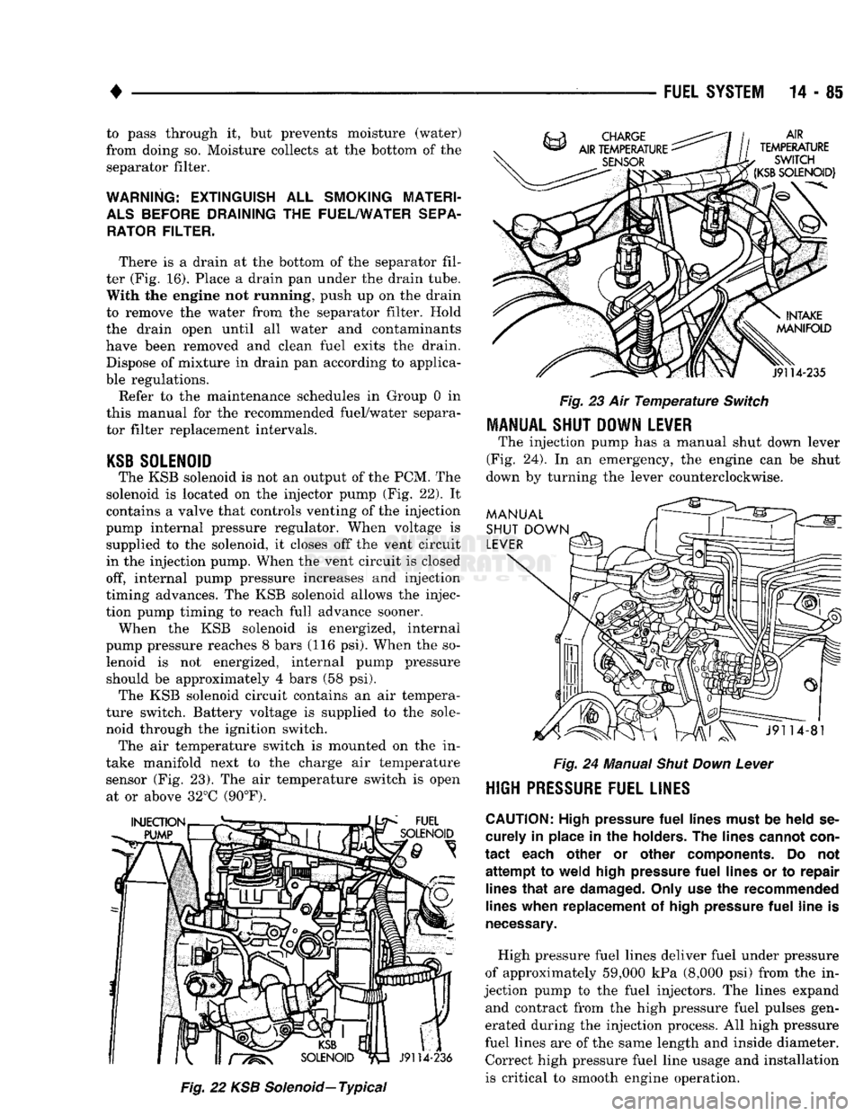
The KSB solenoid is not an output of the PCM. The
solenoid is located on the injector pump (Fig. 22). It
contains a valve that controls venting of the injection
pump internal pressure regulator. When voltage is supplied to the solenoid, it closes off the vent circuit
in the injection pump. When the vent circuit is closed
off, internal pump pressure increases and injection
timing advances. The KSB solenoid allows the injec
tion pump timing to reach full advance sooner. When the KSB solenoid is energized, internal
pump pressure reaches 8 bars (116 psi). When the so lenoid is not energized, internal pump pressure should be approximately 4 bars (58 psi). The KSB solenoid circuit contains an air tempera
ture switch. Battery voltage is supplied to the sole
noid through the ignition switch. The air temperature switch is mounted on the in
take manifold next to the charge air temperature sensor (Fig. 23). The air temperature switch is open at or above 32°C (90°F).
Fig.
22 KSB
Solenoid—
Typical
Fig.
23 Air
Temperature
Switch
MANUAL SHUT DOWN LEVER
The injection pump has a manual shut down lever
(Fig. 24). In an emergency, the engine can be shut
down by turning the lever counterclockwise.
Fig.
24 Manual
Shut
Down
Lever
HIGH
PRESSURE FUEL LINES
CAUTION:
High pressure
fuel
lines must
be
held
se
curely
in
place
in the
holders.
The
lines cannot con
tact
each other
or
other components.
Do not
attempt
to
weld high pressure
fuel
lines
or to
repair lines
that
are
damaged. Only use
the
recommended
lines when replacement
of
high pressure
fuel
line
is
necessary.
High pressure fuel lines deliver fuel under pressure
of approximately 59,000 kPa (8,000 psi) from the in
jection pump to the fuel injectors. The lines expand and contract from the high pressure fuel pulses gen
erated during the injection process. All high pressure
fuel lines are of the same length and inside diameter. Correct high pressure fuel line usage and installation
is critical to smooth engine operation.