battery DODGE TRUCK 1993 Service Repair Manual
[x] Cancel search | Manufacturer: DODGE, Model Year: 1993, Model line: TRUCK, Model: DODGE TRUCK 1993Pages: 1502, PDF Size: 80.97 MB
Page 15 of 1502
10 INTRODUCTION
•
INTERNATIONAL CONTROL AND DISPLAY SYMBOLS
ID
HIGH
BEAM P
FOG UGHTS -&
HEADLIGHTS,
PARKING UGHTS, PANEL UGHTS TURN SIGNAL A
HAZARD WARNING WINDSHIELD
WASHER
WINDSHIELD WIPER WINDSHIELD WIPER
AND WASHER
AND DEFROSTING *
VENTILATING
FAN 8
M f
REAR
WINDOW DEFOGGER
sp
REARWINLX)W WIPER
CD
l
m
REAR
WINDOW WASHER FUEL ENGINE COOLANT
TEMPERATURE BATTERY CHARGING
CONDITION ENGINE OIL
SEAT
BELT
(©) (®) ky
11 J
LIGHTER
BRAKE
FAILURE
PARKING
BRAKE
FRONT HOOD
REAR
HOOD
(TRUNK)
HORN
11 J
LIGHTER
93IN-9
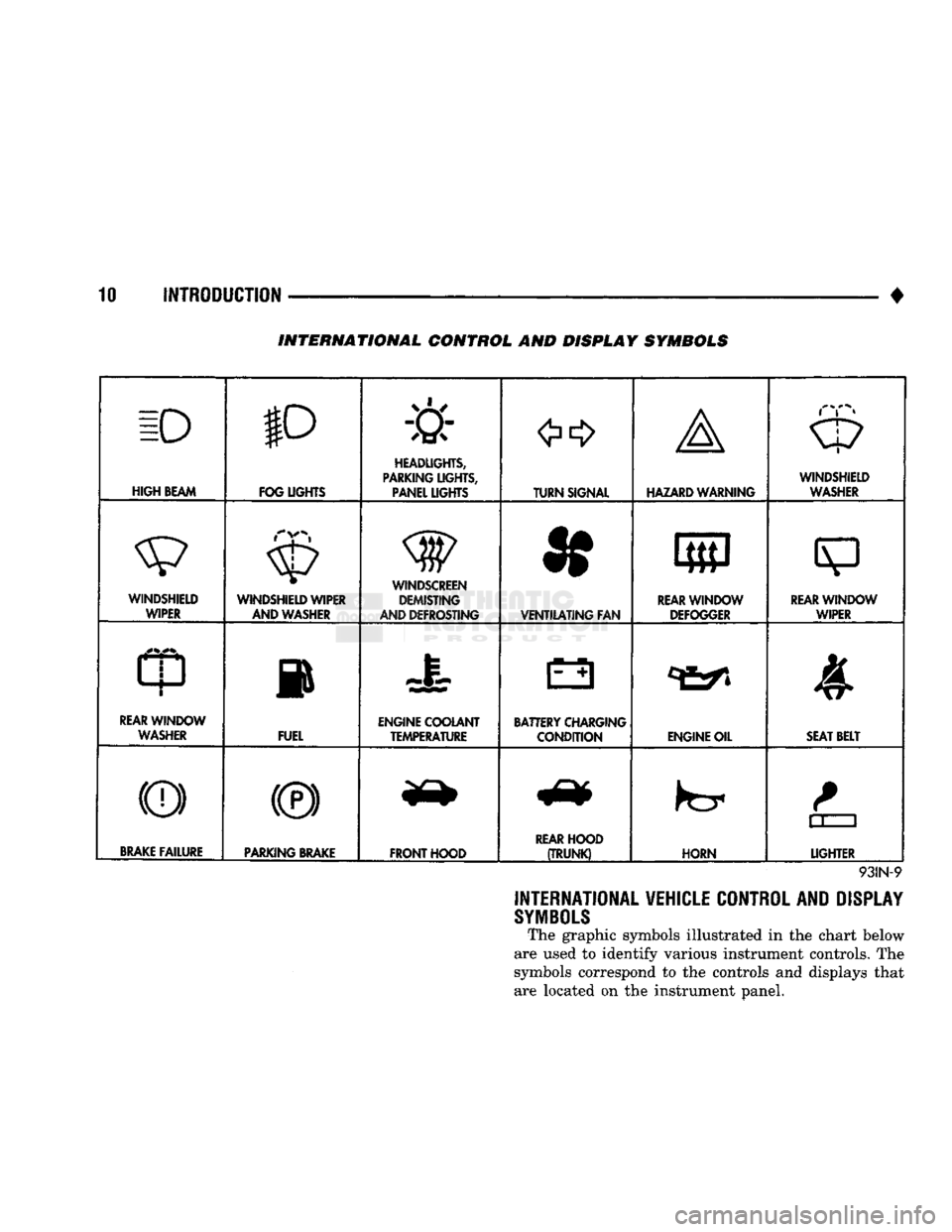
INTERNATIONAL VEHICLE CONTROL AND DISPLAY
SYMBOLS
The graphic symbols illustrated in the chart below
are used to identify various instrument controls. The
symbols correspond to the controls and displays that are located on the instrument panel.
Page 21 of 1502
0 - 2
LUBRICATION
AND
MAINTENANCE
• Commercial service
When a vehicle is continuously subjected to severe
driving conditions, lubricate:
• Body components
• All the driveline coupling joints
• Steering linkage More often than normal driving conditions
DUSTY
AREAS
With this type of severe driving condition, special
care should be given to the:
• Engine air cleaner filter
• PCV filter
• Crankcase ventilation system
• Brake booster control valve air filter. Verify that the filters and the associated compo
nents are clean. Also verify that they are functioning
effectively. This will minimize the amount of abra sive particles that enter the engine.
OFF-ROAD
(4WD)
OPERATION
After off-road (4WD) operation, inspect the under
side of the vehicle. Inspect the:
• Tires
• Body structure
• Steering components
• Suspension components • Exhaust system
• Threaded fasteners
HARSH
SURFACE ENVIRONMENTS
After extended operation in harsh environments,
the brake drums, brake linings, and rear wheel bear ings should be inspected and cleaned. This will pre
vent wear and erratic brake action.
ROUTINE MAINTENANCE
The following routine maintenance is recommended
on a monthly basis: TIRES—Inspect the tires for unusual wear/damage.
Determine if the inflation pressure is adequate for
the vehicle load. BATTERY—Inspect and clean the terminals.
Tighten the terminals if necessary. FLUIDS—Determine if the component fluid levels
are acceptable. Add fluid, if necessary. LIGHTS/ELECTRICAL—Test all the electrical sys
tems in the vehicle for proper operation. It is also recommended that the engine oil and the
washer fluid level be determined at each fuel fill-up.
VEHICLE
NOISE CONTROL
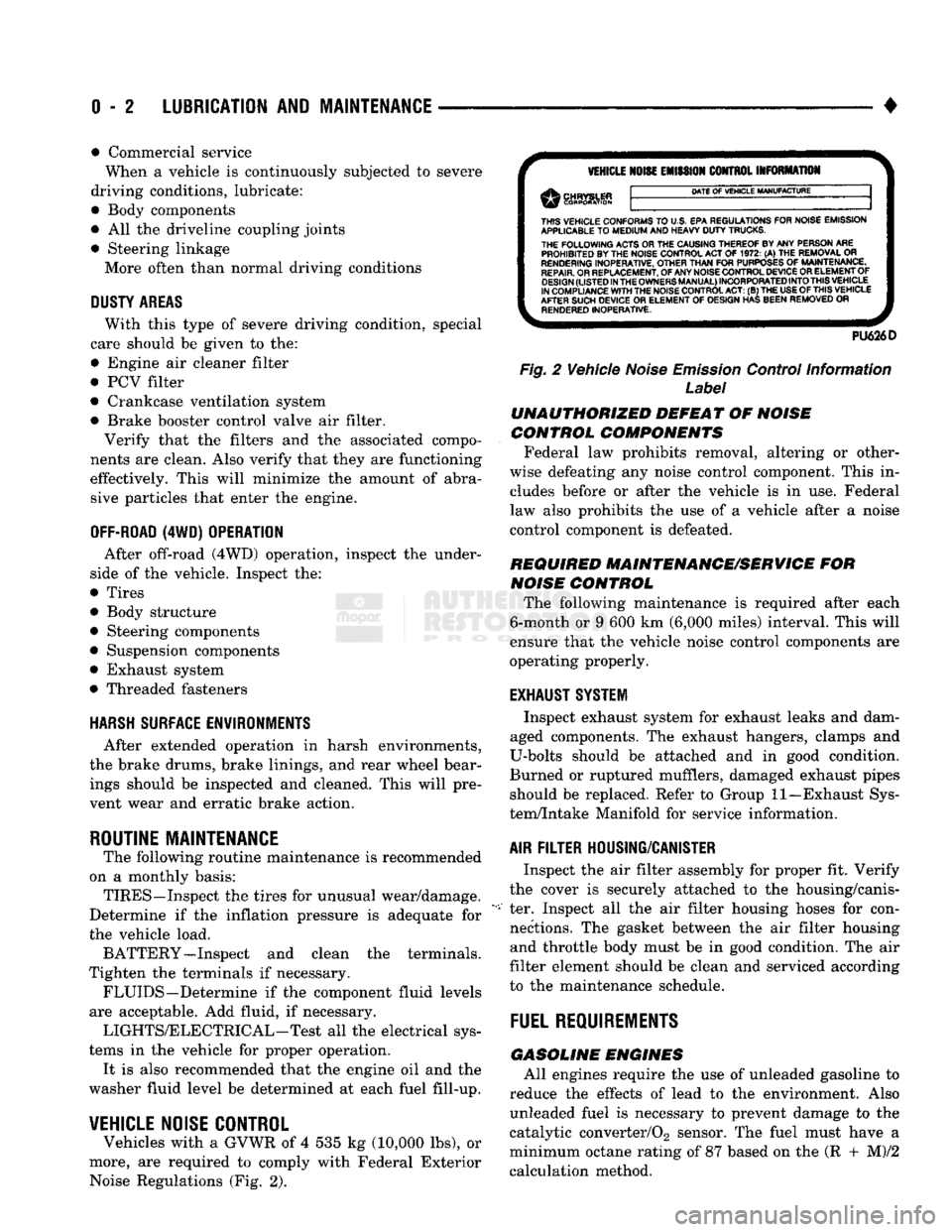
Vehicles with a GVWR of 4 535 kg (10,000 lbs), or
more, are required to comply with Federal Exterior Noise Regulations (Fig. 2).
VEHICLE
NOISE
EMISSION
CONTROL INFORMATION
DATE
OF
VEHICLE
MANUFACTURE
THIS
VEHICLE CONFORMS
TO
U.S. EPA REGULATIONS FOR NOISE EMISSION
APPLICABLE
TO
MEDIUM
AND HEAVY
DUTY
TRUCKS. THE
FOLLOWING
ACTS OR THE CAUSING THEREOF BY ANY PERSON ARE PROHIBITED BY THE NOISE CONTROL ACT
OF 1972. (A) THE
REMOVAL
OR
RENDERING
INOPERATIVE, OTHER
THAN
FOR
PURPOSES
OF
MAINTENANCE,
REPAIR.
OR REPLACEMENT, OF ANY NOISE CONTROL DEVICE OR ELEMENT OF
DESIGN
(LISTED
IN
THE
OWNERS
MANUAL)
INCORPORATED
INTO
THIS
VEHICLE
IN COMPLIANCE
WITH
THE NOISE CONTROL
ACT:
(B) THE
USE
OF
THIS
VEHICLE
AFTER SUCH DEVICE
OR
ELEMENT
OF
DESIGN HAS BEEN REMOVED
OR
RENDERED
INOPERATIVE.
PU626D
Fig.
2 Vehicle
Noise
Emission
Control Information
Label
UNAUTHORIZED
DEFEAT
OF
NOISE
CONTROL COMPONENTS
Federal law prohibits removal, altering or other
wise defeating any noise control component. This in
cludes before or after the vehicle is in use. Federal
law also prohibits the use of a vehicle after a noise
control component is defeated.
REQUIRED MAINTENANCE/SERVICE
FOR
NOISE
CONTROL
The following maintenance is required after each
6-month or 9 600 km (6,000 miles) interval. This will
ensure that the vehicle noise control components are
operating properly.
EXHAUST SYSTEM
Inspect exhaust system for exhaust leaks and dam
aged components. The exhaust hangers, clamps and
U-bolts should be attached and in good condition.
Burned or ruptured mufflers, damaged exhaust pipes should be replaced. Refer to Group 11—Exhaust Sys
tem/Intake Manifold for service information.
AIR
FILTER
HOUSING/CANISTER
Inspect the air filter assembly for proper fit. Verify
the cover is securely attached to the housing/canis
ter. Inspect all the air filter housing hoses for con nections. The gasket between the air filter housing and throttle body must be in good condition. The air
filter element should be clean and serviced according
to the maintenance schedule.
FUEL
REQUIREMENTS
GASOLINE
ENGINES
All engines require the use of unleaded gasoline to
reduce the effects of lead to the environment. Also unleaded fuel is necessary to prevent damage to the
catalytic converter/02 sensor. The fuel must have a
minimum octane rating of 87 based on the (R + M)/2
calculation method.
Page 24 of 1502
GASOLINE ENGINE MAINTENANCE SCHEDULE
LIGHT
DUTY
CYCLE
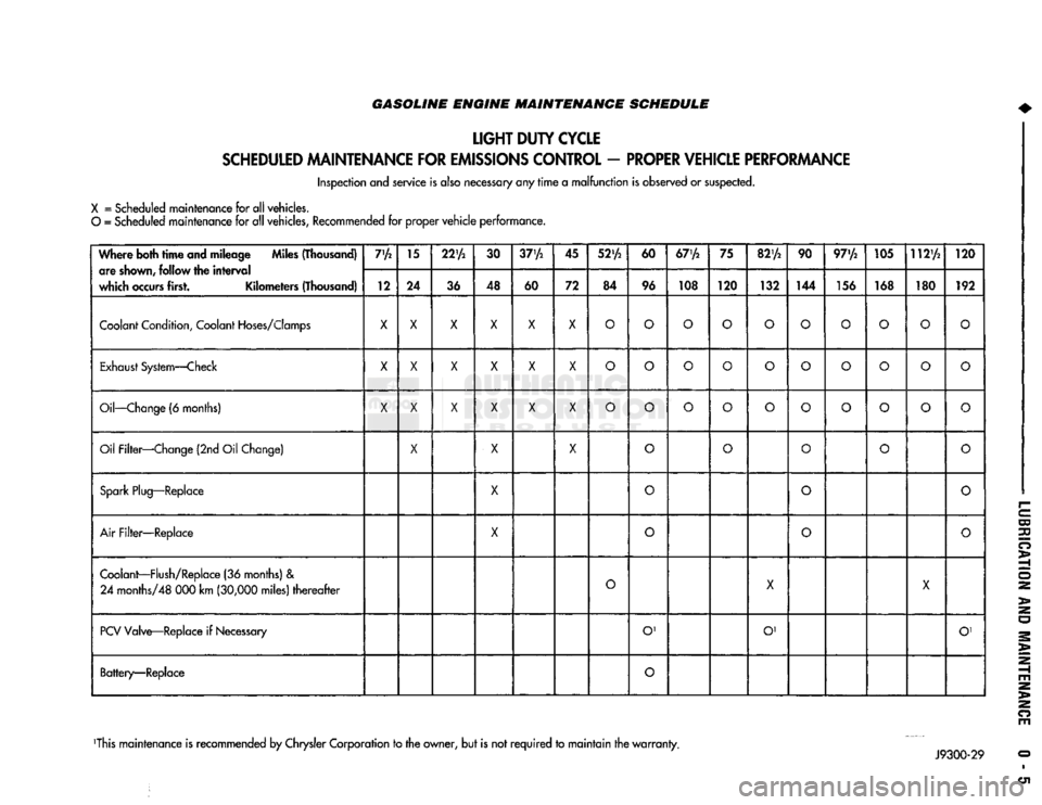
SCHEDULED
MAINTENANCE
FOR
EMISSIONS
CONTROL
-
PROPER
VEHICLE
PERFORMANCE
Inspection and service is also necessary any
rime
a
malfunction
is observed or suspected.
X
= Scheduled maintenance for all vehicles.
O
= Scheduled maintenance for all vehicles, Recommended for proper
vehicle
performance.
Where both
time
and mileage Miles (Thousand) are
shown,
follow the
interval
which
occurs
first. Kilometers (Thousand) 7'A
15
22'A
30
37'A
45
52'A
60
67'A
75
82'A
90 97'/2 105 112'A
120
Where both
time
and mileage Miles (Thousand)
are
shown,
follow the
interval
which
occurs
first. Kilometers (Thousand) 12 24
36 48
60 72 84 96 108 120
132 144 156 168 180 192
Coolant
Condition,
Coolant
Hoses/Clomps
X X X X X X
O O O O O
O O O
o
O
Exhaust
System—Check
X
X X X X
X
O O O
o
O
O O
o o o
Oil—Change
(6 months)
X X X X X X
O O O
o o
O O
o o
o
Oil Filter—Change (2nd Oil Change)
X
X X
o o
O
o
o
Spark
Plug—Replace
X
0
o o
Air
Filter—Replace
X
o
O
o
Coolant—Flush/Replace
(36 months) &
24
months/48 000 km
(30,000
miles)
thereafter
O
X
X
PCV
Valve—Replace if
Necessary
O'
O' O'
Battery—Replace
O
This maintenance is recommended by Chrysler Corporation to the owner, but is not
required
to
maintain
the
warranty.
Page 25 of 1502
0 - 6
LUBRICATION
AND
MAINTENANCE
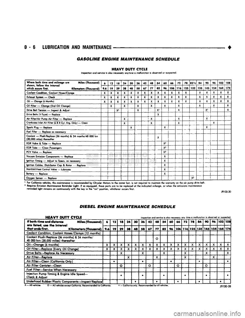
GASOLINE ENGINE MAINTENANCE SCHEDULE
HEAVY
DUTY
CYCLE
Inspection and service is also necessary anytime
a
malfunction is observed or suspected.
When both
time
and mileage
are
Miles (Thousand)
shewn,
follow
the
interval
which occurs first. Kilometers (Thousand) 6
12 18 24
30 36 42 48 54
60 66 72
78
82V2
84 90
96
102 108
When both
time
and mileage
are
Miles (Thousand)
shewn,
follow
the
interval
which occurs first. Kilometers (Thousand) 9.6 19 29
38 48 58 67 77
85 96 106 116
125 132
135
145
154 164
174
Coolant
Condition, Coolant
Hoses/Clamps
X
X X X
X X X X
X X X X
X X X
X X X
Exhaust
System
—
Check
X X X X X X X X X X X
X X X X X
X X
Oil
—
Change
(6
Months)
X X X X X X X
X X
X
X
X
X X X
X X
X
Oil
Filter
—
Change (2nd
Oil
Change)
X X X X
X X
X X
X
Drive Belt Tension
—
Inspect
&
Adjust
X' X
X1
X X' X
Drive Belts (V-Type)
—
Replace
X
Air
Filter/Air
Pump
Air
Filter
—
Replace
X X X
X
Crankcase
Inlet
Air
Filter
(6 &
8
Cyl.
Eng.
Only)
—
Clean
X X
X X
Spark
Plug
—
Replace
X X X
Fuel
Filter
—
Replace as necessary
Coolant
—
Flush/Replace
(36
months)
& 24
months/48
000 km
(30,000
miles)
thereafter
X
EGR
Valve
&
Tube
—
Replace X2
EGR
Tube
—
Clean Passengers
X2
PCV
Valve
—
Replace X2
Vacuum
Emission
Components
—
Replace
X
Ignition Timing
—
Adjust
to
Specs,
as necessary X
Ignition Cables, Distributor Cap
&
Rotor
—
Replace
X
Manifold Heat Control Valve
—
Lubricate
X
Battery
—
Replace X
Oxygen
Sensor
—
Replace
X2
1 For California vehicles, this maintenance is recommended
by
Chrysler Motors
to the
owner but, is not
required
to
maintain the
warranty
on the
air
pump drive
belt.
2 Requires
Emission
Maintenance Reminder Light.
If
so equipped, these parts
are to be
replaced
at the
indicated mileage,
or
when the
emissions
maintenance reminded light remains on continuously
with
the key in the
"on" position, whichever occurs first.
J9100-20
DIESEL
ENGINE
MAINTENANCE
SCHEDULE
HEAVY
DUTY
CYCLE
Inspection
and
service
is
also
necessary
any
time
a
malfunction
is
observed
or
suspected.
Iff both
time
and distance Miles (Thousand)
are listed, use the
interval
that
ends
first. Kilometers (Thousand) 6
12
18 24
30 36 42
4S
54
60 66
72 78
84 90 96
102 108
Iff both
time
and distance Miles (Thousand)
are listed, use the
interval
that
ends
first. Kilometers (Thousand) 9,6 19
29
38 48 58 67
77
85 96 106
116 125 135 145 154
164 174
Coolant
Condition, Coolant
Hoses/Clamps
(12 months)
Coolant
Flush/Replace (36 months) & 24 months/
48 000 km
(30,000
miles)
thereafter
O
Oil—Change
(6 months)
X X X
X X X
X X X X X
X X X X X X
X
Oil Filter—Replace (Every Oil Change)
X X X
X X X
X X
X X X
X
X X X X
X X
Drive Belts—Replace
As
Necessary
X X
X X X X
Air Filter—Replace
X X
X X
Air Filter—Clean (California Only) e
®
• •
Air
Filter
Canister—Clean
o o o
o
Fuel Filter—Service When Necessary
Injection
Pump
Timing & Engine Idle Speed—
Check
& Adjust
©
• 9 • • •
Underhood Rubber/Plastic Components—Inspect/Replace • • • • •
X
— All vehicles
O
— All
vehicles
except
California.
Recommended
for
California.
•
— California only.
Recommended
for all vehicles.
Page 28 of 1502
•
LUBRICATION AND MAINTENANCE
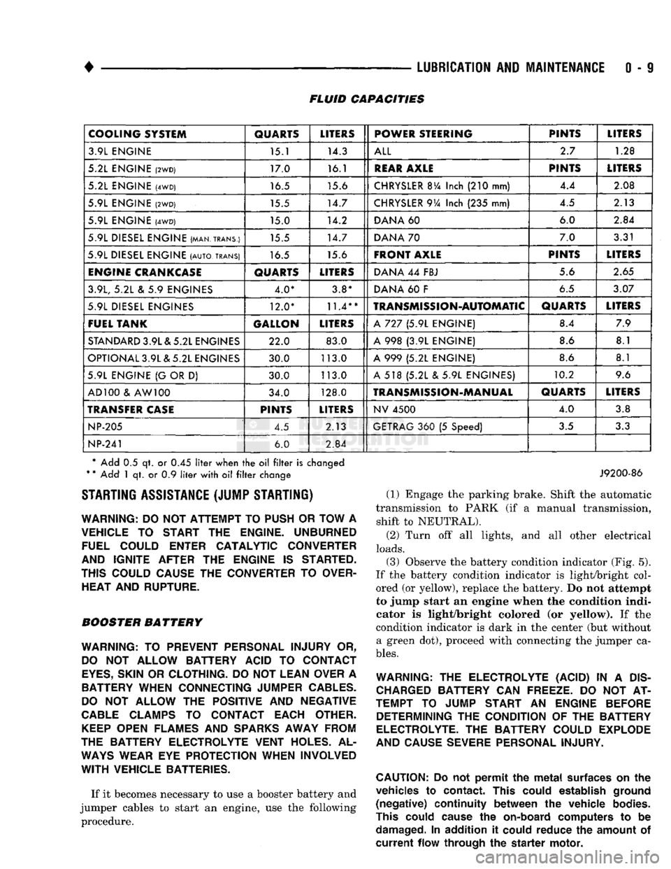
0 - 9 FLUID CAPACITIES
COOLING SYSTEM
QUARTS
LITERS
POWER STEERING PINTS
LITERS
3.9L ENGINE 15.1 14.3
ALL
2.7
1.28
5.2L ENGINE
(2WD)
17.0 16.1
REAR
AXLE
PINTS
LITERS
5.2L ENGINE
(4WD)
16.5 15.6
CHRYSLER
BVa
Inch
(210
mm) 4.4
2.08
5.9L ENGINE
(2WD)
15.5 14.7
CHRYSLER
9Va
Inch
(235
mm) 4.5
2.13
5.9L ENGINE
(4WD)
15.0 14.2
DANA
60 6.0
2.84
5.9L DIESEL ENGINE (MAN.TRANS.) 15.5 14.7
DANA
70 7.0
3.31
5.9L DIESEL ENGINE
(AUTO,
TRANS)
16.5 15.6
FRONT AXLE
PINTS
LITERS
ENGINE
CRANKCASE
QUARTS
LITERS
DANA
44
FBJ 5.6
2.65
3.9L,
5.2L & 5.9
ENGINES 4.0* 3.8*
DANA
60 F
6.5
3.07
5.9L DIESEL ENGINES 12.0*
11.4**
TRANSMISSION-AUTOMATIC
QUARTS
LITERS
FUEL TANK GALLON
LITERS
A
727 (5.9L
ENGINE) 8.4
7.9
STANDARD
3.9L & 5.2L ENGINES 22.0 83.0
A
998 (3.9L
ENGINE) 8.6
8.1
OPTIONAL 3.9L & 5.2L ENGINES 30.0 113.0
A
999 (5.2L
ENGINE) 8.6
8.1
5.9L ENGINE
{G
OR
D)
30.0 113.0
A
518 (5.2L & 5.9L
ENGINES) 10.2
9.6
AD 100
&
AW 100 34.0 128.0
TRANSMISSION-MANUAL
QUARTS
LITERS
TRANSFER
CASE
PINTS
LITERS
NV
4500
4.0
3.8
NP-205
4.5 2.13
GETRAG
360 (5
Speed)
3.5
3.3
NP-241
6.0
2.84
* Add
0.5 qt. or 0.45
liter
when
the oil filter
is
changed
*
*
Add
1 qt. or 0.9
liter
with
oil filter
change STARTING ASSISTANCE (JUMP STARTING)
WARNING:
DO NOT
ATTEMPT
TO
PUSH
OR
TOW
A
VEHICLE
TO
START
THE
ENGINE. UNBURNED FUEL COULD ENTER CATALYTIC CONVERTER
AND IGNITE AFTER
THE
ENGINE
IS
STARTED.
THIS COULD CAUSE
THE
CONVERTER
TO
OVER HEAT AND RUPTURE.
BOOSTER BATTERY
WARNING:
TO
PREVENT PERSONAL INJURY
OR,
DO
NOT
ALLOW BATTERY ACID
TO
CONTACT
EYES,
SKIN
OR
CLOTHING.
DO NOT
LEAN OVER
A
BATTERY WHEN CONNECTING JUMPER
CABLES.
DO
NOT
ALLOW
THE
POSITIVE
AND
NEGATIVE
CABLE
CLAMPS
TO
CONTACT EACH OTHER.
KEEP
OPEN FLAMES
AND
SPARKS
AWAY FROM
THE BATTERY ELECTROLYTE VENT HOLES.
AL
WAYS
WEAR
EYE
PROTECTION WHEN INVOLVED
WITH
VEHICLE BATTERIES.
If it becomes necessary to use a booster battery and
jumper cables to start an engine, use the following procedure.
J9200-86
(1) Engage the parking brake. Shift the automatic
transmission to PARK (if a manual transmission, shift to NEUTRAL).
(2) Turn off all lights, and all other electrical
loads.
(3)
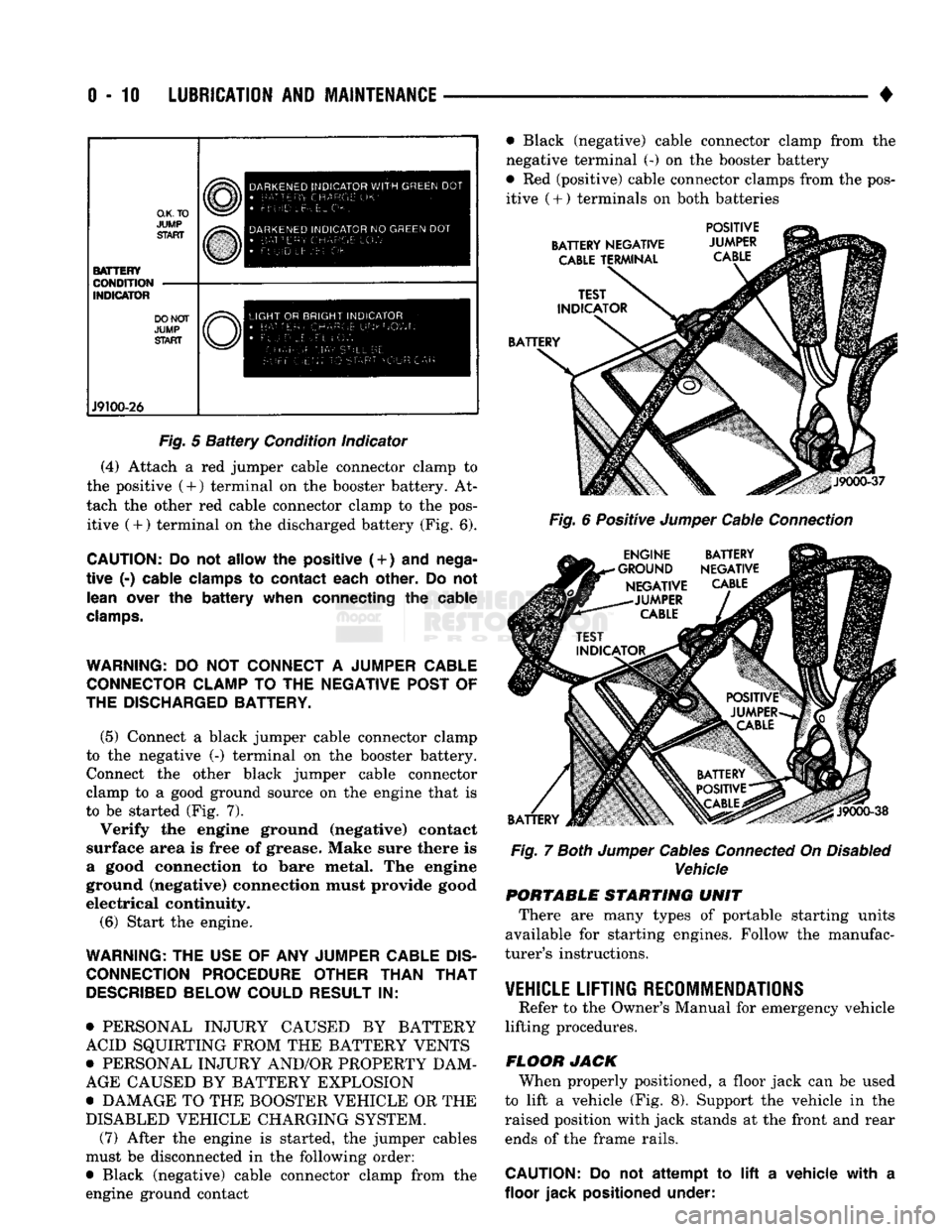
Observe the battery condition indicator (Fig. 5).
If the battery condition indicator is light/bright col
ored (or yellow), replace the battery. Do not attempt
to jump start an engine when the condition indi
cator is light/bright colored (or yellow). If the
condition indicator is dark in the center (but without a green dot), proceed with connecting the jumper ca
bles.
WARNING:
THE
ELECTROLYTE (ACID)
IN A
DIS
CHARGED
BATTERY
CAN
FREEZE.
DO NOT AT
TEMPT
TO
JUMP START
AN
ENGINE BEFORE DETERMINING
THE
CONDITION
OF THE
BATTERY
ELECTROLYTE.
THE
BATTERY COULD EXPLODE
AND CAUSE SEVERE PERSONAL INJURY.
CAUTION:
Do not
permit
the
metal
surfaces
on the
vehicles
to
contact.
This
could
establish
ground
(negative)
continuity
between
the
vehicle
bodies.
This
could
cause
the
on-board
computers
to be
damaged.
In
addition
it
could
reduce
the
amount
of
current
flow
through
the
starter
motor.
Page 29 of 1502
0-10
LUBRICATION
AND
MAINTENANCE
•
O.K.TO
JUMP
START BATTERY
CONDITION
INDICATOR DO NOT
JUMP
START J9100-26 DARKENED
INDICATOR
WITH
GREEN
DOT
•
LETTERS
Uk-
FLUID
Lt- E:L .
DARKENED
INDICATOR
NO
GREEN
DOT •
BATTERY CHARGE
10'//
• Ft UID
L
EVEl
OK
LIGHT
OR
BRIGHT
INDICATOR
•
RAT-cci,
C
H
A
P
C;
F
R^'^Owh
AM.w-GE
FlAf StIll BE
r-
•
!
F-
r tjr r
?
STA
F
•
r
O U n
C
AI:
Fig.
5
Battery
Condition indicator
(4) Attach a red jumper cable connector clamp to
the positive (4-) terminal on the booster battery. At
tach the other red cable connector clamp to the pos itive (+) terminal on the discharged battery (Fig. 6).
CAUTION:
Do not
allow
the
positive (
+
)
and
nega
tive
(-)
cable clamps
to
contact each other.
Do not
lean over
the
battery when connecting
the
cable
clamps.
WARNING:
DO NOT
CONNECT
A
JUMPER CABLE CONNECTOR CLAMP
TO THE
NEGATIVE POST
OF
THE DISCHARGED BATTERY.
(5) Connect a black jumper cable connector clamp
to the negative (-) terminal on the booster battery. Connect the other black jumper cable connector
clamp to a good ground source on the engine that is
to be started (Fig. 7).
Verify the engine ground (negative) contact
surface area is free of grease. Make sure there is
a good connection to bare metal. The engine
ground (negative) connection must provide good
electrical continuity.
(6) Start the engine.
WARNING:
THE
USE
OF ANY
JUMPER CABLE
DIS
CONNECTION PROCEDURE OTHER THAN
THAT
DESCRIBED
BELOW COULD RESULT
IN:
• PERSONAL INJURY CAUSED BY BATTERY
ACID SQUIRTING FROM THE BATTERY VENTS
• PERSONAL INJURY AND/OR PROPERTY DAM
AGE CAUSED BY BATTERY EXPLOSION
• DAMAGE TO THE BOOSTER VEHICLE OR THE
DISABLED VEHICLE CHARGING SYSTEM. (7) After the engine is started, the jumper cables
must be disconnected in the following order:
• Black (negative) cable connector clamp from the
engine ground contact • Black (negative) cable connector clamp from the
negative terminal (-) on the booster battery
• Red (positive) cable connector clamps from the pos itive
(
+ ) terminals on both batteries
BATTERY NEGATIVE
CABLE
TERMINAL POSITIVE
JUMPER
CABLE
BATTERY
J9000-37
Fig.
6 Positive
Jumper
Cable
Connection
ENGINE BATTERY
•GROUND NEGATIVE NEGATIVE
CABLE
-JUMPER
CABLE
BATTERY
J9000-38
Fig.
7
Both
Jumper
Cables
Connected
On
Disabled
Vehicle PORTABLE STARTING UNIT
There are many types of portable starting units
available for starting engines. Follow the manufac
turer's instructions.
VEHICLE
LIFTING RECOMMENDATIONS
Refer to the Owner's Manual for emergency vehicle
lifting procedures.
FLOOR JACK When properly positioned, a floor jack can be used
to lift a vehicle (Fig. 8). Support the vehicle in the
raised position with jack stands at the front and rear ends of the frame rails.
CAUTION:
Do not
attempt
to lift a
vehicle with
a
floor jack positioned under:
Page 33 of 1502
0 - 14
LUBRICATION
AND
MAINTENANCE
•
ENGINE
MAINTENANCE
INDEX
page
Air
Injection
Systems/Air Pump
. 17
Air-Conditioner
Compressor
21
Battery
19
Cooling System
15
Crankcase
Ventilation
System
17
Diesel Engine
Air Filter
Canister
17
Drive Belts
20
Engine
Air
Cleaner
Filter
Element
16
Engine Break-In
14
Engine
Oil 14
Engine
Oil
Change
and Filter
Replacement
15
Exhaust Gas
Recirculation
(EGR) System
...... 19
page
Exhaust
Manifold
Heat
Control
Valve
. 17
Exhaust System
, 21
Fuel System
18
Hoses
and
Fittings
16
Ignition
Cables,
Distributor
Cap and
Rotor
...... 19
Ignition
Timing
. 19
Oxygen
(02)
Sensor
19
Rubber/Plastic Components
20
Spark Plugs
. 19
Throttle
Control
Linkage
18
Vacuum Operated, Emission
Control
Components
19
ENGINE BREAK-IN
After first starting a new engine, allow it to idle
for 15 seconds before shifting into a drive gear. Also:
• Drive the vehicle at varying speeds less than 88
km/h (55 mph) for the first 480 km (300 miles).
• Avoid fast acceleration and sudden stops.
• Do not drive at full-throttle for extended periods of
time
• Do not drive at constant speeds
• Do not idle the engine excessively A special break-in engine oil is not required. The
original engine oil installed is a high quality lubri
cant. New engines tend to consume more fuel and oil un
til after the break-in period has ended.
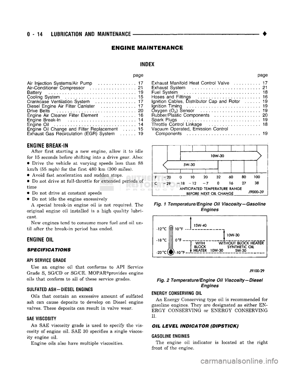
ENGINE
OIL SPECIFICATIONS
API SERWICE
GRADE
Use an engine oil that conforms to API Service
Grade S5 SG/CD or SG/CE. MOPAR®provides engine
oils that conform to all of these service grades.
SULFATED ASH—DIESEL ENGINES
Oils that contain an excessive amount of sulfated
ash can cause deposits to develop on Diesel engine
valves. These deposits can result in valve wear.
SAE
WISC0SITY
An SAE viscosity grade is used to specify the vis
cosity of engine oil. SAE 30 specifies a single viscos
ity engine oil.
Engine oils also have multiple viscosities. 10W-30
<
5W-30
1
1 1
F
-20 0 10 20 32 60 80 100
C
-29 -18 -12 -7 0 16 27 38
ANTICIPATED
TEMPERATURE RANGE BEFORE
NEXT
OIL
CHANGE
J9000-39
Fig.
1 Temperature/Engine Oil Viscosity—Gasoline
Engines
-12°C
-18°C 10°F
0°F- 15W-40
-23°c(^-10eF
I
10W-30
WITH
WITHOUT
BLOCK HEATER
BLOCK
SYNTHETIC
OIL
HEATER
10W-30 5W-30
J9100-29
Fig.
2 Temperature/Engine Oil Viscosity—Diesel
Engines
ENERGY
G0NSERWING
OIL
An Energy Conserving type oil is recommended for
gasoline engines. They are designated as either EN
ERGY CONSERVING or ENERGY CONSERVING
II.
OIL
LEVEL
INDICATOR (DIPSTICK)
GASOLINE ENGINES
The engine oil indicator is located at the right
front of the engine.
Page 38 of 1502
•
LUBRICATION
AND
MAINTENANCE
0 - 19 ETBE— This fuel is a mixture of unleaded gasoline
and up to 17 percent ETBE (Ethyl Tertiary Butyl
Ether).
Unleaded gasoline blended with ETBE is ac ceptable.
METHANOL—Do not use unleaded gasoline
blended with methanol. The use of this type of alco hol can result in engine performance and damage to
critical components. Engine problems that result
from the use of methanol possibly will not be covered by the new vehicle warranty.
Certain brands of unleaded gasoline contain a per
centage of unidentified alcohol. These types of un
leaded gasoline are not recommended.
ADDITIVES MIXED
WITH
GASOLINE
Use of fuel system cleaning additives should be
avoided. Many of these solutions could contain highly
active solvents. This type of solvent can be harmful
to the gasket and diaphragm material within the fuel system.
DIESEL
ENGINE FUEL REQUIREMENTS
All Diesel engines normally can use number 2D
Diesel fuel for most year-round operations. A fuel
conforming to ASTM Specification D-975 is recom
mended. For extreme cold-weather operation (below
-18°C/0°F), or for prolonged cold-climate operation ei
ther:
• Use No. ID fuel, or
• Add an equal quantity of kerosene to No. 2D fuel (a 50/50 mixture).
Both methods provide protection against fuel gel
ling and waxing.
Diesel fuel seldom is without water contamination.
To help prevent fuel system malfunctions, drain all accumulated water from the separators periodically.
VACUUM OPERATED,
EMISSION
CONTROL
COMPONENTS
MAINTENANCE SCHEDULE
The following emission controls should be replaced
at the interval specified in the maintenance sched
ule:
• Bi-level purge check valves
• Delay valves
• Heated air temperature sensor (HATS)
• Air cleaner vacuum motors
EXHAUST
GAS RECIRCULATION (EGR)
SYSTEM
MAINTENANCE SCHEDULE
Replace the EGR valve and tube, and clean the
passages at the interval specified in maintenance schedule. If necessary, refer to Group 25—Emission
Control Systems for additional information.
OXYGEN
(02)
SENSOR
MAINTENANCE SCHEDULE
Replace the 02 sensor at the interval specified in
maintenance schedule.
IGNITION
CABLES,
DISTRIBUTOR CAP AND
ROTOR
MAINTENANCE SCHEDULE
Replace the ignition cables, distributor cap, and ro
tor at the interval specified in maintenance schedule.
Inspect the distributor for excessive wear and re
place, as necessary. Refer to Group 8D—Ignition Sys
tems for additional information.
IGNITION TIMING
MAINTENANCE SCHEDULE
Test and adjust, if necessary, the ignition timing at
the interval specified in maintenance schedule. Refer
to the specifications listed on the engine Emission Control Information label. Refer to Group 8D—Igni
tion Systems and to Group 25—Emission Control Systems for additional service information.
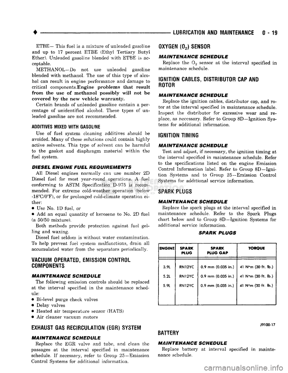
SPARK
PLUGS MAINTENANCE SCHEDULE
Replace the spark plugs at the interval specified in
maintenance schedule. Refer to the Spark Plugs
chart below and to Group 8D—Ignition Systems for additional service information.
SPARK
PLUGS
ENGINE
SPARK
PLUG
SPARK
PLUG
GAP
TORQUE
3.9L
5.2L
5.9L
RN12YC
RN12YC
RN12YC
0.9 mm
(0.035
in.)
0.9 mm
(0.035
in.)
0.9 mm
(0.035
in.) 41 N*m (30 ft. lb.)
41 NVn (30 ft. lb.)
41 N*m (30 ft. lb.)
J9100-17
BATTERY
MAINTENANCE SCHEDULE
Replace battery at interval specified in mainte
nance schedule.
Page 39 of 1502
0
- 21
LUBRICATION
AND
MAINTENANCE
• SERVICE INFORMATION
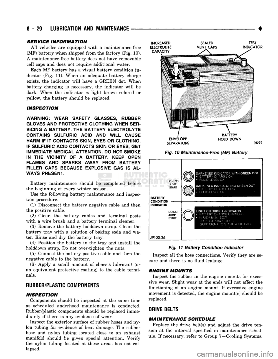
All vehicles are equipped with a maintenance-free
(MF) battery when shipped from the factory (Fig. 10).
A maintenance-free battery does not have removable
cell caps and does not require additional water. Each MF battery has a visual battery condition in
dicator (Fig. 11). When an adequate battery charge
exists,
the indicator will have a GREEN dot. When
battery charging is necessary, the indicator will be dark. When the indicator is light brown colored or
yellow, the battery should be replaced.
INSPECTION
WARNING; WEAR SAFETY
GLASSES,
RUBBER
GLOVES
AND
PROTECTIVE CLOTHING WHEN SER
VICING
A
BATTERY.
THE
BATTERY ELECTROLYTE CONTAINS SULFURIC ACID
AND
WILL CAUSE HARM
IF IT
CONTACTS SKIN, EYES
OR
CLOTHING.
IF SULFURIC ACID CONTACTS SKIN
OR
EYES,
GET
IMMEDIATE MEDICAL ATTENTION.
DO
NOT
SMOKE
IN
THE
VICINITY
OF A
BATTERY. KEEP OPEN
FLAMES
AND
SPARKS AWAY FROM BATTERY
FILLER CAPS BECAUSE EXPLOSIVE
GAS IS AL
WAYS
PRESENT.
Battery maintenance should be completed before
the beginning of every winter season.
Use the following battery maintenance and inspec
tion procedure. (1) Disconnect the battery negative cable and then
the positive cable.
(2) Clean the battery cables and terminal posts
with a wire brush and a battery terminal cleaner. (3) Remove the battery holddown strap. Clean the
battery tray with a solution of baking soda and wa
ter. Rinse and dry the battery tray.
(4) Position the battery in the tray and install the
holddown strap. Do not over-tighten the nuts.
(5) Connect the battery positive cable and then the
negative cable to the battery.
(6) Apply a small amount of chassis lubricant (or
an equivalent protective coating) to the cable termi
nals.
RUBBER/PLASTIC
COMPONENTS
INSPECTION Components should be inspected at the same time
as scheduled underhood maintenance is conducted.
Rubber/plastic components should be replaced imme diately if there is any evidence of wear. Inspect the exterior surface of rubber hoses and ny
lon tubing for evidence of heat damage. The rubber
hose and nylon tubing located close to an exhaust
manifold should be given special attention. Verify
the nylon tubing located at these areas has not col lapsed.
INCREASED
ELECTROUTE CAPACITY
SEALED
VENT
CAPS TEST
INDICATOR ENVELOPE
SEPARATORS
BATTERY
HOLD DOWN
RK92
Fig. 10 Maintenance-Free (MF)
Battery
O.K. TO
JUMP START
BATTERY
CONDITION
INDICATOR
J9100-26
DARKENED
INDICATOR
WITH
GREEN
DOT
•
BATTERY CHARGE
OK '
•
FLUID LEVEL
OK
DARKENED
INDICATOR
NO
GREEN
DOT
•
BATTERY CHARGE
LOW
FLUID LEVEL
OK
LIGHT
OR
BRIGHT INDICATOR
•
BATTERY CHARGE UNKNOWN
•
FLUID uEv'EL
LOW
(CHARGE
MAY
STILL
BE
SUFFICIENT
TO
START YOUR
CAR)
Fig. 11
Battery
Condition Indicator
Inspect all the hose connections. Verify they are se
cure and there is no fluid leakage.
ENGINE MOUNTS Inspect the rubber in the engine mounts for exces
sive wear. Slight wear at the ends will not affect the
functioning of an engine mount. If excessive engine
movement is detected, the engine mount(s) should be
replaced.
DRIVE
BELTS
MAINTENANCE SCHEDULE Replace the drive belt(s) and adjust the drive ten
sion at the interval specified in maintenance sched
ule.
If necessary, refer to Group 7—Cooling Systems.
Page 210 of 1502
•
BRAKES
5 - 23
VACUUM PUMP OPERATION
Vacuum pump output is transmitted to the power
brake booster through a supply hose. The hose is con nected to an outlet port on the pump housing and to
the check valve in the power brake booster.
Pump output ranges from a minimum of 8.5 to 25
inches vacuum. The pump rotor and vanes are rotated by the pump
drive gear. The drive gear is operated by the cam
shaft gear. Booster vacuum level is monitored by a warning
switch (Fig. 2). The switch consists of a vacuum
chamber that measures vacuum level and a sensor in
circuit with the brake warning light. The vacuum chamber is connected to the booster
check valve by a vacuum supply hose. A wire har
ness connects the switch sensor to the brake warning
light. If booster vacuum falls below 8.5 inches for 8-10 seconds or more, the switch sensor completes
the circuit to the warning light causing it to illumi
nate.
VACUUM PUMP DIAGNOSIS
Vacuum pump diagnosis involves checking pump
output with a vacuum gauge. The low vacuum warn
ing switch can also be checked with a vacuum gauge.
Refer to the diagnosis procedure in this section. A standard vacuum gauge can be used to check
pump output when necessary. Simply disconnect the
pump supply hose and connect a vacuum gauge to
the outlet port for testing purposes. Vacuum should
hold steady in a range of approximately 8.5 to 25 inches at various engine speeds.
DIAGNOSING LOW VACUUM OUTPUT CONDITION A low booster vacuum condition or a faulty low
vacuum warning switch will cause the brake warn ing light to illuminate. If the light does go on and in
dicates the existence of a low vacuum condition,
check the vacuum pump, booster and warning switch
as follows:
(1) Check vacuum pump oil feed line. Verify that
line connections are secure and not leaking. If leak age is noted and pump is noisy, replace pump.
(2) Disconnect supply hose to booster. Connect vac
uum gauge to this hose and run engine at various
throttle openings. Output should range from 8.5 to 25 inches vacuum. If vacuum is consistently below
8.5 inches, problem is with vacuum hoses or pump
component. If output is within specified limits, con
tinue testing.
(3) Check booster operation as described in diagno
sis section. Replace check valve, vacuum hoses, or
booster if necessary. However, if booster operation is correct but warning light is still on, continue testing. (4) Disconnect vacuum hose at warning switch.
Plug hose and connect hand vacuum pump to switch. (5) Start and run engine.
(6) Apply 8.5 to 9 inches of vacuum to warning
switch and observe warning light. If light goes out,
switch vacuum hose is either loose or leaking. If
light remains on, leave engine running and continue
testing.
(7) Apply 20-25 inches vacuum to switch and ob
serve warning light operation. If light now goes out,
switch is at fault and should be replaced. If light re
mains on, continue testing.
(8) Reconnect vacuum hoses and replace original
warning switch with known good switch. Run engine and observe warning light operation. If light is now
off, old switch is faulty. If light remains on, problem
is in wiring between switch and warning light.
VACUUM-STEERING PUMP
ASSEMBLY
REMOVAL
(1) Disconnect battery negative cable.
(2) Position drain pan under power steering pump.
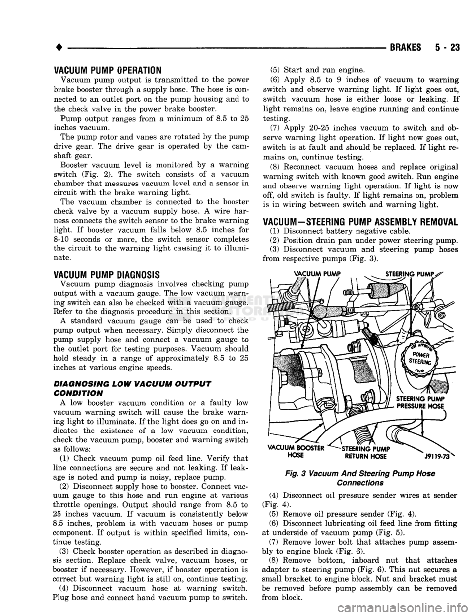
(3) Disconnect vacuum and steering pump hoses
from respective pumps (Fig. 3).
Fig.
3
Vacuum
And Steering
Pump Hose
Connections
(4) Disconnect oil pressure sender wires at sender
(Fig. 4).
(5) Remove oil pressure sender (Fig. 4).
(6) Disconnect lubricating oil feed line from fitting
at underside of vacuum pump (Fig. 5).
(7) Remove lower bolt that attaches pump assem
bly to engine block (Fig. 6).
(8) Remove bottom, inboard nut that attaches
adapter to steering pump (Fig. 6). This nut secures a
small bracket to engine block. Nut and bracket must
be removed before pump assembly can be removed from block.