stop start DODGE TRUCK 1993 Service User Guide
[x] Cancel search | Manufacturer: DODGE, Model Year: 1993, Model line: TRUCK, Model: DODGE TRUCK 1993Pages: 1502, PDF Size: 80.97 MB
Page 213 of 1502
5
- 26
BRAKES
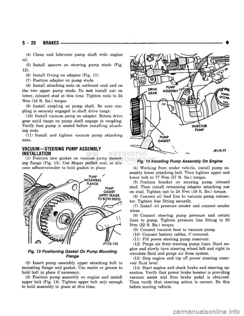
Fig. 13 Positioning Gasket On Pump Mounting
Flange
(2) Insert pump assembly upper attaching bolt in
mounting flange and gasket. Use sealer or grease to
hold bolt in place if necessary.
(3) Position pump assembly on engine and install
upper bolt (Fig. 14). Tighten upper bolt only enough
to hold assembly in place at this time. •
Fig. 14 Installing Pump Assembly On Engine (4) Working from under vehicle, install pump as
sembly lower attaching bolt. Then tighten upper and
lower bolt to 77 N»m (57 ft. lbs.) torque. (5) Position bracket on steering pump inboard
stud. Then install remaining adapter attaching nut
on stud. Tighten nut to 24 N«m (18 ft. lbs.) torque.
(6) Connect oil feed line to vacuum pump connec
tor. Tighten line fitting securely.
(7) Install oil pressure sender and connect sender
wires.
(8) Connect steering pump pressure and return
lines to pump. Tighten pressure line fitting to 30
N-m (22 ft. lbs.) torque.
(9) Connect vacuum hose to vacuum pump.
(10) Connect battery cables, if removed.
(11) Fill power steering pump reservoir.
(12) Purge air from steering pump lines. Start en
gine and slowly turn steering wheel left and right to circulate fluid and purge air from system.
(13) Stop engine and top off power steering reser
voir fluid level.
(14) Start engine and check brake and steering op
eration. Verify that power brake booster is providing
vacuum assist and firm brake pedal is obtained.
Then verify that steering action is correct. Do this
before moving vehicle.
(4) Clean and lubricate pump shaft with engine
oil.
(5) Install spacers on steering pump studs (Fig.
12).
(6) Install O-ring on adapter (Fig. 11).
(7) Position adapter on pump studs.
(8) Install attaching nuts on outboard stud and on
the two upper pump studs. Do not install nut on
lower, inboard stud at this time. Tighten nuts to 24
N-m (18 ft. lbs.) torque. (9) Install coupling on pump shaft. Be sure cou
pling is securely engaged in shaft drive tangs. (10) Install vacuum pump on adapter. Rotate drive
gear until tangs on pump shaft engage in coupling.
Verify that pump is seated before installing attach
ing nuts. (11) Install and tighten vacuum pump attaching
nuts.
VACUUM-STEERING PUMP ASSEMBLY INSTALLATION
(1) Position new gasket on vacuum pump mount
ing flange (Fig. 13). Use Mopar perfect seal, or sili
cone adhesive/sealer to hold gasket in place.
Page 268 of 1502
•
CLUTCH
6 - 15
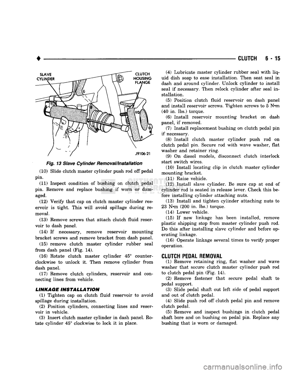
Fig.
13
Slave
Cylinder Removal/Installation (10) Slide clutch master cylinder push rod off pedal
pin.
(11) Inspect condition of bushing on clutch pedal
pin. Remove and replace bushing if worn or dam aged.
(12) Verify that cap on clutch master cylinder res
ervoir is tight. This will avoid spillage during re
moval.
(13) Remove screws that attach clutch fluid reser
voir to dash panel.
(14) If necessary, remove reservoir mounting
bracket screws and remove bracket from dash panel.
(15) remove clutch master cylinder rubber seal
from dash panel (Fig. 14).
(16) Rotate clutch master cylinder 45° counter
clockwise to unlock it. Then remove cylinder from
dash panel. (17) Remove clutch cylinders, reservoir and con
necting lines from vehicle.
LINKAGE
INSTALLATION
(1) Tighten cap on clutch fluid reservoir to avoid
spillage during installation. (2) Position cylinders, connecting lines and reser
voir in vehicle.
(3) Insert clutch master cylinder in dash panel. Ro
tate cylinder 45° clockwise to lock it in place. (4) Lubricate master cylinder rubber seal with liq
uid dish soap to ease installation. Then seat seal in
dash and around cylinder. Unlock cylinder to install
seal if necessary. Then relock cylinder after seal in stallation.
(5) Position clutch fluid reservoir on dash panel
and install reservoir screws. Tighten screws to 5 N»m (40 in. lbs.) torque.
(6) Install reservoir mounting bracket on dash
panel, if removed.
(7) Install replacement bushing on clutch pedal pin
if necessary. (8) Install clutch master cylinder push rod on
clutch pedal pin. Secure rod with wave washer, flat
washer and retainer ring.
(9) On diesel models, disconnect clutch interlock
start switch wires.
(10) Install locating clip in clutch master cylinder
mounting bracket.
(11) Raise vehicle.
(12) Install slave cylinder. Be sure cap at end of
cylinder rod is seated in release lever. Check this be
fore installing cylinder attaching nuts. (13) Install and tighten cylinder attaching nuts to
23 N*m (200 in. lbs.) torque.
(14) Lower vehicle.
(15) If new linkage has been installed, remove
plastic shipping stop from master cylinder push rod. Do this after installing slave cylinder and before operating linkage.
(16) Operate linkage several times to verify proper
operation.
CLUTCH
PEDAL REMOVAL
(1) Remove retaining ring, flat washer and wave
washer that secure clutch master cylinder push rod
to clutch pedal pin (Fig. 14). (2) Remove fastener that secure pedal shaft to
pedal support. (3) Slide pedal shaft out left side of pedal support
and out of clutch pedal. (4) Slide push rod off clutch pedal pin and remove
clutch pedal. (5) Remove and inspect bushings in clutch pedal
shaft bore and on bushing on pedal pin. Replace any
bushing that is worn or damaged.
Page 299 of 1502
7 - 28
COOLING SYSTEM
DO NOT WASTE reusable coolant. If the solution
is clean, drain the coolant into a clean container for
reuse.
(1) Start the engine and place the heater control
temperature selector in the Full On position. Engine vacuum is needed to actuate the heater controls.
(2) Turn the ignition off. (3) Do not remove radiator cap when draining cool
ant from reserve/overflow tank. Open radiator drain
plug and when tank is empty, remove radiator cap. If
the coolant reserve/overflow tank does not drain, re fer to the Testing Cooling System for Leaks section
in this group. The coolant need not be removed from
tank unless the system is being refilled with fresh mixture.
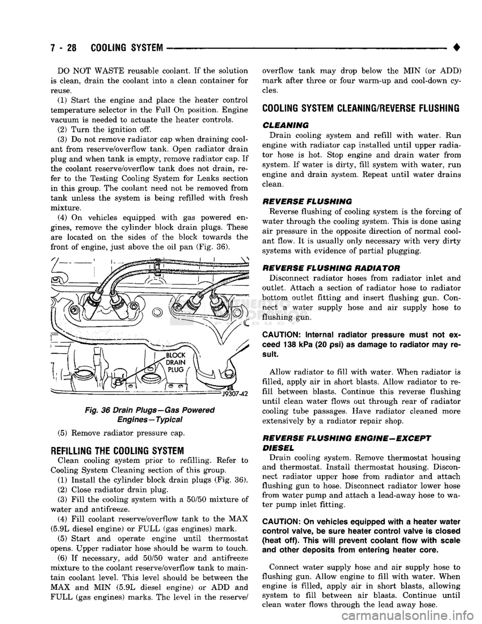
(4) On vehicles equipped with gas powered en
gines,
remove the cylinder block drain plugs. These are located on the sides of the block towards the
front of engine, just above the oil pan (Fig. 36).
Fig.
36 Drain Plugs—Gas Powered
Engines—Typical
(5) Remove radiator pressure cap.
REFILLING
THE
COOLING SYSTEM
Clean cooling system prior to refilling. Refer to
Cooling System Cleaning section of this group. (1) Install the cylinder block drain plugs (Fig. 36).
(2)
Close radiator drain plug.
(3) Fill the cooling system with a 50/50 mixture of
water and antifreeze. (4) Fill coolant reserve/overflow tank to the MAX
(5.9L diesel engine) or FULL (gas engines) mark. (5) Start and operate engine until thermostat
opens. Upper radiator hose should be warm to touch. (6) If necessary, add 50/50 water and antifreeze
mixture to the coolant reserve/overflow tank to main
tain coolant level. This level should be between the MAX and MIN (5.9L diesel engine) or ADD and FULL (gas engines) marks. The level in the reserve/ overflow tank may drop below the MIN (or ADD)
mark after three or four warm-up and cool-down cy
cles.
COOLING SYSTEM CLEANING/REVERSE FLUSHING
CLEMMING Drain cooling system and refill with water. Run
engine with radiator cap installed until upper radia
tor hose is hot. Stop engine and drain water from system. If water is dirty, fill system with water, run
engine and drain system. Repeat until water drains
clean.
REVERSE
FLUSHING
Reverse flushing of cooling system is the forcing of
water through the cooling system. This is done using air pressure in the opposite direction of normal cool
ant flow. It is usually only necessary with very dirty
systems with evidence of partial plugging.
REVERSE
FLUSHING
RADIATOR Disconnect radiator hoses from radiator inlet and
outlet. Attach a section of radiator hose to radiator
bottom outlet fitting and insert flushing gun. Con
nect a water supply hose and air supply hose to flushing gun.
CAUTION:
Internal
radiator
pressure must
not'ex
ceed 138 kPa (20 psi) as damage to
radiator
may re
sult
Allow radiator to fill with water. When radiator is
filled, apply air in short blasts. Allow radiator to re
fill between blasts. Continue this reverse flushing
until clean water flows out through rear of radiator cooling tube passages. Have radiator cleaned more extensively by a radiator repair shop.
REVERSE
FLUSHING
ENGINE-EXCEPT DIESEL Drain cooling system. Remove thermostat housing
and thermostat. Install thermostat housing. Discon
nect radiator upper hose from radiator and attach
flushing gun to hose. Disconnect radiator lower hose
from water pump and attach a lead-away hose to wa
ter pump inlet fitting.
CAUTION;
On vehicles equipped
with
a
heater
water
control
valve, be sure
heater
control
valve is closed
(heat
off). This
will
prevent
coolant
flow
with
scale
and
other
deposits
from
entering
heater
core.
Connect water supply hose and air supply hose to
flushing gun. Allow engine to fill with water. When engine is filled, apply air in short blasts, allowing system to fill between air blasts. Continue until
clean water flows through the lead away hose.
Page 300 of 1502
+
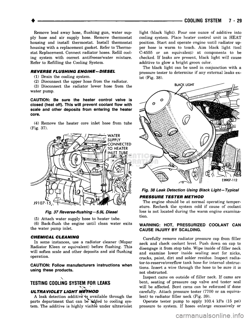
Fig.
37
Reverse-flushing—5.9L
Diesel
(5) Attach water supply hose to heater tube.
(6) Back-flush the engine until clean water exits
the water pump inlet.
CHEMICAL
CLEANING
In some instances, use a radiator cleaner (Mopar
Radiator Kleen or equivalent) before flushing. This
will soften scale and other deposits and aid flushing operation.
CAUTION;
Follow manufacturers instructions when
using
these
products.
TESTING
COOLING
SYSTEM
FOR
LEAKS
ULTRAVIOLET
LIGHT
METHOD
A leak detection additive is available through the
parts department that can be Sidfled to cooling sys
tem. The additive is highly visible under ultraviolet
COOLING
SYSTEM
7 - 29
Fig.
38
Leak
Detection
Using
Black
Light—Typical
PRESSURE
TESTER
METHOD
The engine should be at normal operating temper
ature. Recheck the system cold if cause of coolant
loss is not located during the warm engine examina
tion.
WARNING:
HOT,
PRESSURIZED
COOLANT
CAN
CAUSE
INJURY
BY
SCALDING.
Carefully remove radiator pressure cap from filler
neck and check coolant level. Push down on cap to
disengage it from stop tabs. Wipe inside of filler neck and examine lower inside sealing seat for nicks,
cracks, paint, dirt and solder residue. Inspect radia
tor-to-reserve/overflow tank hose for internal obstruc
tions.
Insert a wire through the hose to be sure it is
not obstructed.
Inspect cams on outside of filler neck. If cams are
bent, seating of pressure cap valve and tester seal
will be affected. Bent cams can be reformed if done carefully. Attach pressure tester (7700 or an equivalent) to radiator filler neck (Fig. 39).
Operate tester pump to apply 103.4 kPa (15 psi)
pressure to system. If hoses enlarge excessively or
Remove lead away hose, flushing gun, water sup
ply hose and air supply hose. Remove thermostat housing and install thermostat. Install thermostat
housing with a replacement gasket. Refer to Thermo stat Replacement. Connect radiator hoses. Refill cool
ing system with correct antifreeze/water mixture.
Refer to Refilling the Cooling System.
REVERSE
FLUSHING
ENGINE-DIESEL
(1) Drain the cooling system. (2) Disconnect the upper hose from the radiator.
(3) Disconnect the radiator lower hose from the
water pump.
CAUTION;
Be
sure
the
heater
control valve is
closed
(heat
off).
This
will
prevent coolant flow
with
scale
and other
deposits
from entering the
heater
core.
(4) Remove the heater core inlet hose from tube
(Fig. 37). light (black light). Pour one ounce of additive into
cooling system. Place heater control unit in HEAT
position. Start and operate engine until radiator up
per hose is warm to touch. Aim black light (tool C-4555 or an equivalent) at components to be
checked. If leaks are present, black light will cause additive to glow a bright green color.
The black light can be used in conjunction with a
pressure tester to determine if any external leaks ex ist (Fig. 38).
Page 387 of 1502
8E
- 6
INSTRUMENT PANEL
AND
GAUGES
•
(5)
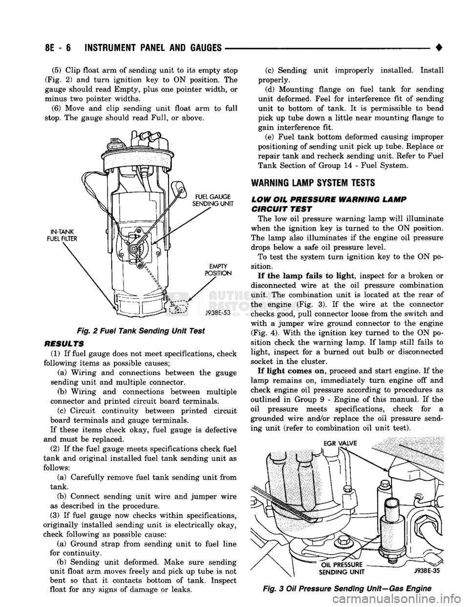
Clip float arm of sending unit to its empty stop
(Fig. 2) and turn ignition key to ON position. The
gauge should read Empty, plus one pointer width, or
minus two pointer widths.
(6) Move and clip sending unit float arm to full
stop.
The gauge should read Full, or above.
Fig. 2 Fuel Tank Sending Unit Test
RESULTS (1) If fuel gauge does not meet specifications, check
following items as possible causes; (a) Wiring and connections between the gauge
sending unit and multiple connector. (b) Wiring and connections between multiple
connector and printed circuit board terminals.
(c) Circuit continuity between printed circuit
board terminals and gauge terminals.
If these items check okay, fuel gauge is defective
and must be replaced.
(2) If the fuel gauge meets specifications check fuel
tank and original installed fuel tank sending unit as follows:
(a) Carefully remove fuel tank sending unit from
tank.
(b) Connect sending unit wire and jumper wire
as described in the procedure.
(3) If fuel gauge now checks within specifications,
originally installed sending unit is electrically okay,
check following as possible cause:
(a) Ground strap from sending unit to fuel line
for continuity. (b) Sending unit deformed. Make sure sending
unit float arm moves freely and pick up tube is not
bent so that it contacts bottom of tank. Inspect float for any signs of damage or leaks. (c) Sending unit improperly installed. Install
properly.
(d) Mounting flange on fuel tank for sending
unit deformed. Feel for interference fit of sending
unit to bottom of tank. It is permissible to bend
pick up tube down a little near mounting flange to gain interference fit.
(e) Fuel tank bottom deformed causing improper
positioning of sending unit pick up tube. Replace or
repair tank and recheck sending unit. Refer to Fuel
Tank Section of Group 14 - Fuel System.
WARNING
LAMP
SYSTEM
TESTS
LOW
OH.
PRESSURE WARNING LAMP CIRCUIT
TEST
The low oil pressure warning lamp will illuminate
when the ignition key is turned to the ON position.
The lamp also illuminates if the engine oil pressure drops below a safe oil pressure level.
To test the system turn ignition key to the ON po
sition.
If the lamp fails to light, inspect for a broken or
disconnected wire at the oil pressure combination
unit. The combination unit is located at the rear of
the engine (Fig. 3). If the wire at the connector checks good, pull connector loose from the switch and
with a jumper wire ground connector to the engine (Fig. 4). With the ignition key turned to the ON po
sition check the warning lamp. If lamp still fails to
light, inspect for a burned out bulb or disconnected
socket in the cluster.
If light comes on, proceed and start engine. If the
lamp remains on, immediately turn engine off and
check engine oil pressure according to procedures as
outlined in Group 9 - Engine of this manual. If the
oil pressure meets specifications, check for a
grounded wire and/or replace the oil pressure send
ing unit (refer to combination oil unit test). Fig. 3 Oil Pressure Sending Unit—Gas Engine
Page 418 of 1502
VEHICLE
SPEED
CONTROL
SYSTEM
8H - 3
GAS
ENGINE
warnings the usi of THE
SPEED
control is NOT recommended when
DRIVING
CONDITIONS
DO not
PERMIT
maintaining
A
constant
SPEED, SUCH
AS
HEAVY
TRAFFIC
©r on
ROADS
THAT ARE
WINDING, ICY, SNOW COVERED
OR
SLIPPERY*
START
ENGINE
r
ACCELERATE
VEHICLE TO DESIRED SPEED
SPEED
CONTROL
ENGAGES
WHEN
mmm is
STARTED
PUSH
ON/OFF
BUTTON
TO "ON"
POSITION.
E
FAULTY
ELECTRICAL CIRCUIT*
SPEED
CONTROL ENGAGES
WITHOUT
PUSHING
THE
"SET/DECEL"
BUTTON
PUSH
AND
RELEASE
"SET/DECEL'
'
BUTTON
FAULTY
ELECTRICAL CIRCUIT* DEFECTIVE SERVO
i
DEFECTIVE SERVO
REMOVE
FOOT
FROM
ACCELERATOR.
SPEED
SHOULD
BE
CONTROLLED
T
1
i
1
*
NO
WEED
CONTROL
WHEN
SET/DECEL
BUTTON IS
PRESSED
AND RELEASED
HUNTING
SURGE
OR
SPEED
VARIATIONS AT
LOW
SPEEDS
EXCESSIVE
SAG
ON
HILLS
OR
IN
TRAILER TOWING
SPEED
SETTING AFTER
LOCK-IN,
TOO
HIGH
C3«t LOW
4 *
FUSE
BLOWN
LOCK-UP
TORQUE CONVERTER
ROUGHNESS
ENGINE
PERFORMANCE
VACUUM LEAK
# f
t f
NO
VACUUM
AT
SERVO
AMPLIFICATION
OF ENGINE
SURGE
VACUUM
LEAK
DEFECTIVE SERVO
1
f
it
t
t
SPEED
CONTROL
THROTTLE
CABLE
DISCONNECTED
DEFECTIVE SERVO
EXCESSIVE
LOAD
MAY
REQUIRE MANUAL
ASSISTANCE
ON
HILLS DEFECTIVE
CABLE
i
f
f • *
IMPROPER
STOP LAMP
AND
SPEED CONTROL SWITCH ADJUSTMENT DEFECTIVE
CABLE
DEFECTIVE VACUUM
RESERVOIR
(CHECK VALVE) DEFECTIVE
VACUUM RESERVOIR
1
f
*
FAULTY
ELECTRICAL CIRCUIT* DEFECTIVE
ENGINE
CONTROLLER
DEFECTIVE SERVO
* TESTS AND
ADJUSTMENTS
ARE DESCRIBED
IN
APPROPRIATE
SECTION
OF SERVICE
MANUAL.
DEFECTIVE VACUUM
RESERVOIR
J918H-7
Page 420 of 1502
•
^ ^ VEHICLE
SPEED
CONTROL
SYSTEM
8H - I
WARNING:
THE USE OF THE
SPEED
CONTROL
IS
NOT
RECOMMENDED
WHEN DRIVING
CONDITIONS
DO NOT PERMIT MAINTAINING
A
CONSTANT
SPEED,
SUCH AS HEAVY
TRAFFIC
OR ON
ROADS
THAT
ARE WINDING,
ICY,
SNOW
COVERED
OR
SLIPPERY*
SPEED
CONTROL
ENGAGES
WITHOUT PUSHING THE
"SET/DECEL"
BUTTON
±
FAULTY
ELECTRICAL CIRCUIT*
±
DEFECTIVE
SERVO
START ENGINE
ACCELERATE
VEHICLE TO DESIRED SPEED
PUSH
ON/OFF
BUTTON
TO "ON" POSITION.
PUSH
AND
RELEASE
"SET/DECEL"
BUTTON
REMOVE
FOOT
FROM
ACCELERATOR.
SPEED
SHOULD BE CONTROLLED
SPEED
CONTROL
ENGAGES
WHEN
ENGINE IS STARTED
FAULTY
ELECTRICAL
CIRCUIT*
T
DEFECTIVE SERVO
NO
SPEED
CONTROL WHEN
SET/DECEL
BUTTON
IS
PRESSED
AND
RELEASED
FUSE
BLOWN
NO VACUUM AT
SERVO
T
SPEED
CONTROL
THROTTLE
CABLE DISCONNECTED
IMPROPER
STOP LAMP AND SPEED CONTROL SWITCH ADJUSTMENT
FAULTY
ELECTRICAL CIRCUIT*
T
DEFECTIVE SERVO
DEFECTIVE
VACUUM PUMP
HUNTING
SURGE
OR
SPEED
VARIATIONS AT LOW
SPEEDS
I
LOCK-UP
TORQUE CONVERTER
ROUGHNESS
AMPLIFICATION OF ENGINE
SURGE
DEFECTIVE SERVO
DEFECTIVE
CABLE
DEFECTIVE
ENGINE CONTROLLER
EXCESSIVE
SAG
ON HILLS OR
IN TRAILER
TOWING
ENGINE
PERFORAAANCE
VACUUM
LEAK
EXCESSIVE
LOAD MAY
REQUIRE
MANUAL
ASSISTANCE
ON HILLS
DEFECTIVE
VACUUM PUMP
SPEED
SETTING AFTER
LOCK-IN,
TOO
HIGH
OR TOO LOW
T
VACUUM LEAK
DEFECTIVE SERVO DEFECTIVE
CABLE
T
DEFECTIVE
VACUUM PUMP
REFER
TO GROUP 5 - BRAKES
FOR VACUUM PUMP DIAGNOSIS.
"TEST AND ADJUSTMENTS ARE DESCRIBED IN APPROPRIATE SECTION OF SERVICE MANUAL.
J928H-15
DIESEL
ENGINE
Page 422 of 1502
•
VEHICLE
SPEED
CONTROL SYSTEM
8H - 7
TEST
PROCEDURES
INDEX
page
Checking
for
Diagnostic
Trouble
Code
7
General
Information
7
Inoperative
System
7
Road
Test
7
Speed
Control
Cable Adjustment—Diesel Engine
. 9
Speed
Control
Cable
Attachment
10
GENERAL
INFORMATION
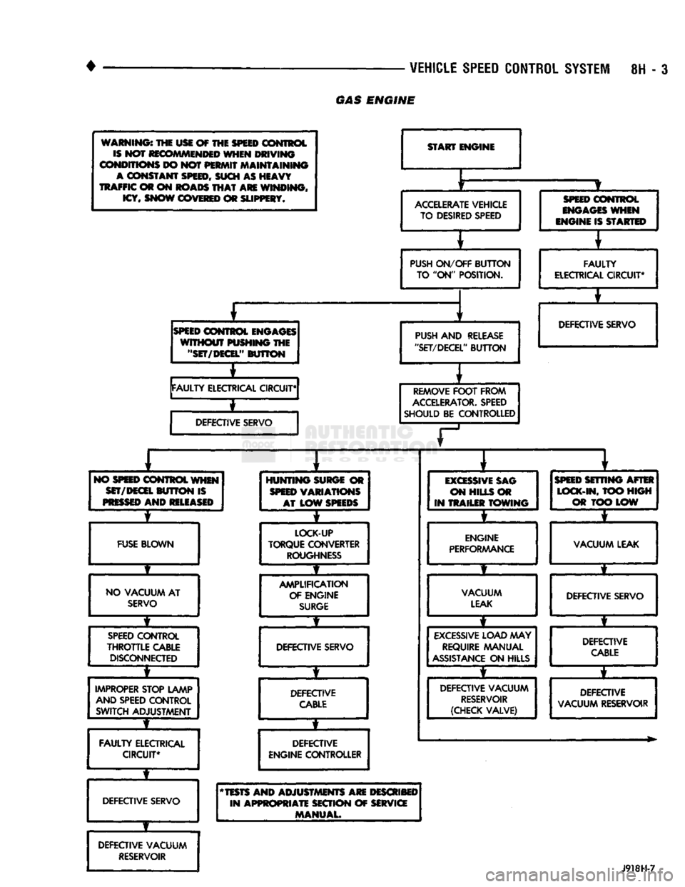
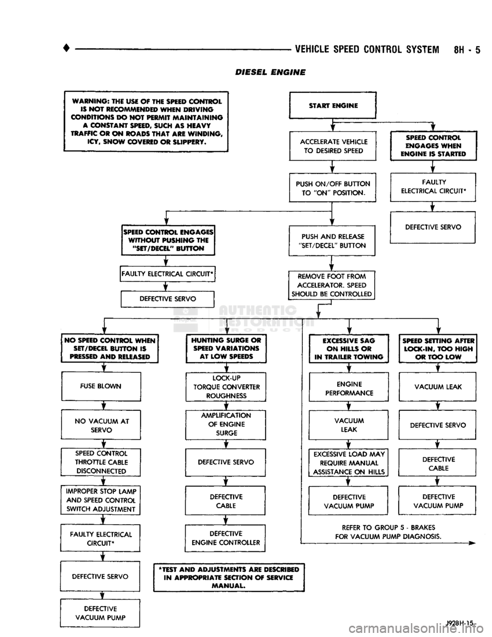
Before starting diagnosis and repair procedures for
a speed control malfunction, verify that the speed
control wire harness is properly connected to all con nectors. Refer to Diagnosis Chart.
ROAD
TEST
Road test vehicle to verify reports of speed control
system malfunction. The road test should include at
tention to the speedometer. Speedometer operation should be smooth and without flutter at all speeds. Flutter in the speedometer indicates a problem
which might cause surging in the speed control sys
tem. The cause of any speedometer deficiencies should be corrected before proceeding.
INOPERATIVE SYSTEM
If road test verifies a system problem and the
speedometer operates properly, check for:
• loose electrical and vacuum connections at the
servo.
• check for correct installation of the vacuum check
valve in the hose from servo to vacuum source (Gas
Engine Only). The word VAC on the valve must
point toward the vacuum source. • corrosion that should be removed from electrical
terminals and a light coating of Mopar Multi-Pur
pose Grease, or equivalent, applied. • secure attachment of both ends of speed control ca
ble.
CHECKING
FOR DIAGNOSTIC TROUBLE CODE
(1) When trying to verify a speed control system
electrical problem, use a DRB II Scan Tool to find
the cause. Refer to Powertrain Diagnostic Procedures manual. If the DRBII is not available, the Diagnostic Trou
ble Code (DTC) may be determined with the follow ing method: (a) With key inserted in ignition switch, cycle
switch to ON position 3 times. On third cycle, leave
switch in ON position. (b) After switch has been cycled 3 times, observe
Malfunction Indicator Lamp (CHECK ENGINE) on instrument cluster. If a DTC is present, the code
page
Speed
Control
Cable Attachment—Servo
10
Stop Lamp Switch Test
9
Vacuum Supply Test
....................... 9
Vehicle Speed
Control
Switch Test
. 9
Vehicle Speed
Control
System
Electrical
Tests
... 7
Vehicle Speed Sensor Test
7
will be displayed in a series of flashes representing
digits.
Three flashes in rapid succession, a slight
pause, then 4 flashes in rapid succession would in dicate DTC 34.
(2) If a DTC 34 is observed, perform the tests in
the sections Electrical Tests at Servo and Electrical
Tests at Powertrain Control Module.
If a DTC 15 is observed, perform the test for a
faulty Vehicle Speed Sensor.
(3) If a fault code 11 is observed (Diesel only), per
form the test for a faulty engine speed sensor. Refer
to the Powertrain Diagnostics Procedures Manual.
(4) Correct any problems found when performing
these tests and recheck for DTC if changes were made.
VEHICLE SPEED SENSOR TEST
For testing of the Vehicle Speed Sensor and related
components refer to the Powertrain Diagnostic Proce
dures manual.
VEHICLE SPEED CONTROL SYSTEM ELECTRICAL
TESTS
Vehicle speed control systems may be tested using
two different methods. One involves the use of the DRBII Scan Tool. If this test method is desired,
please refer to the Powertrain Diagnostic Procedures manual. The other test method uses a voltmeter. The volt
meter method is described in the following tests.
If any information is needed concerning wiring, re
fer to Group 8W - Wiring Diagrams.
CAUTION:
When test probing
for
voltage
or
continuity
at
electrical
connectors, care must
be
taken
not
to
damage connector, terminals,
or
seals.
If
these components
are
damaged,
intermittent
or
complete system
failure
may
occur.
ELECTRICAL
TESTS
AT
SERVO
(1) Turn ignition switch to ON position.
(2) Push speed control switch to ON position.
(3) Connect the negative lead of a voltmeter to a
good chassis ground near the servo.
Page 424 of 1502
![DODGE TRUCK 1993 Service User Guide
VEHICLE
SPEED
CONTROL SYSTEM
8H - 9
rain
oooooooooo
1 10,
.oooooooooo
\21 30
„. \£] 50 x
OOOOOOOOOO OOOOOOOOOO^
11
20
OOOOOOOOOO
51
31 1 6ooooooooo60y/ Tratr
TJKT
RR8HC](/img/12/56922/w960_56922-423.png "DODGE TRUCK 1993 Service User Guide
VEHICLE
SPEED
CONTROL SYSTEM
8H - 9
rain
oooooooooo
1 10,
.oooooooooo
\21 30
„. \£] 50 x
OOOOOOOOOO OOOOOOOOOO^
11
20
OOOOOOOOOO
51
31 1 6ooooooooo60y/ Tratr
TJKT
RR8HC")
VEHICLE
SPEED
CONTROL SYSTEM
8H - 9
rain
oooooooooo
1 10,
.oooooooooo
\21 30
„. \£] 50 x
OOOOOOOOOO OOOOOOOOOO^
11
20
OOOOOOOOOO
51
31 1 6ooooooooo60y/ Tratr
TJKT
RR8HC7
Fig.
4 Powertrain Control Module 60-Way Connector
Shown from Terminal End
from battery voltage to 0 volts for as long as the switch is held. If not, perform the speed control
switch test. If the switch is not at fault, then check
the main harness and repair as necessary.
(6) Touch the positive lead of the voltmeter to the
terminal in cavity number 50. The voltmeter should read 0 volts with the speed control switch in either
the OFF or ON position. With switch in either RE SUME or SET position, the voltmeter should read
battery voltage. If not, perform the speed control switch test. If the switch is not at fault, then check
the main harness and repair as necessary.
(7) Touch the positive lead of the voltmeter to the
terminal in cavity number 49. The voltmeter should read 0 volts with the switch in the OFF position.
With the switch in the ON position, the voltmeter should read battery voltage. The voltmeter will con
tinue to read battery voltage when either the SET or
RESUME switch is pressed. If not, perform the speed control switch test. If the switch is not at fault, then
check the main harness and repair as necessary . (8) Turn key OFF. Using an ohmmeter, connect
one lead to a good body ground and touch the other
lead to the terminal in cavity number 29. With the
brake pedal released, the meter should show continu ity. When the pedal is depressed, the meter should
show open circuit.
VEHICLE
SPEED
CONTROL SWITCH TEST
To check the switch, remove the switch from its
mounting position. Use an ohmmeter and refer to the
Switch Continuity Chart to determine if continuity is
correct. If there is no continuity at any one of the
switch positions, replace the switch.
STOP
LAMP SWITCH TEST
(1) Disconnect connector at stop lamp switch. Us
ing an ohmmeter, continuity may be checked at
switch side of connector as follows (Fig. 5): (a) With brake pedal released, there should be:
• continuity between black (BK) and white with
pink tracer (WT/PK) wires
• continuity between yellow with red tracer (YL/RD) and dark blue with red tracer (DB/RD) wires
• No continuity between pink (PK) and white (WT)
wires.
SPEED CONTROL SWITCH CONTINUITY
CHART
CONNECTOR
TERMINAL
END
JE
El
SWITCH
SPEED
CONTROL
SWITCH
CONTINUITY
SWITCH!
rea?!®^
CONTINUITY
BETWEEN
OFF PIN 1
AND PIN 4
ON PIN
1 AND PIN 4
PIN 1
AND PIN 2
PIN
2 AND PIN 4
ON
AND
SET PIN
1
AN D
PIN 2
ON
AND
RESUME PIN
1 AND PIN 3
J928H-4
(b) With brake pedal depressed, there should be:
• continuity between pink (PK) and white (WT)
wires.
• No continuity between black (BK) and white with
pink tracer (WT/PK) wires.
• No continuity between yellow with red tracer (YL/
RD) and dark blue with red tracer (DB/RD) wires. (2) If the above results are not obtained, the stop
lamp switch is defective or out of adjustment.
Stop lamp switch adjustment is detailed in Group 5 -
Brakes.
VACUUM SUPPLY TEST
(1) Disconnect vacuum hose at the servo and in
stall a vacuum gauge in the hose (Fig. 6). (2) Start engine and observe gauge at idle. Vac
uum gauge should read at least ten inches of mer
cury. (3) If vacuum does not meet this requirement,
check for vacuum leaks or poor engine performance.
SPEED
CONTROL
CABLE
ADJUSTMENT-DIESEL
ENGINE
(1) The gap between the end of the slot on the ca
ble and the bellcrank pin must be as small as possi
ble (0 to 1mm) without moving the throttle. If gap is not correct, remove adjustment clip. Push protective
Page 482 of 1502
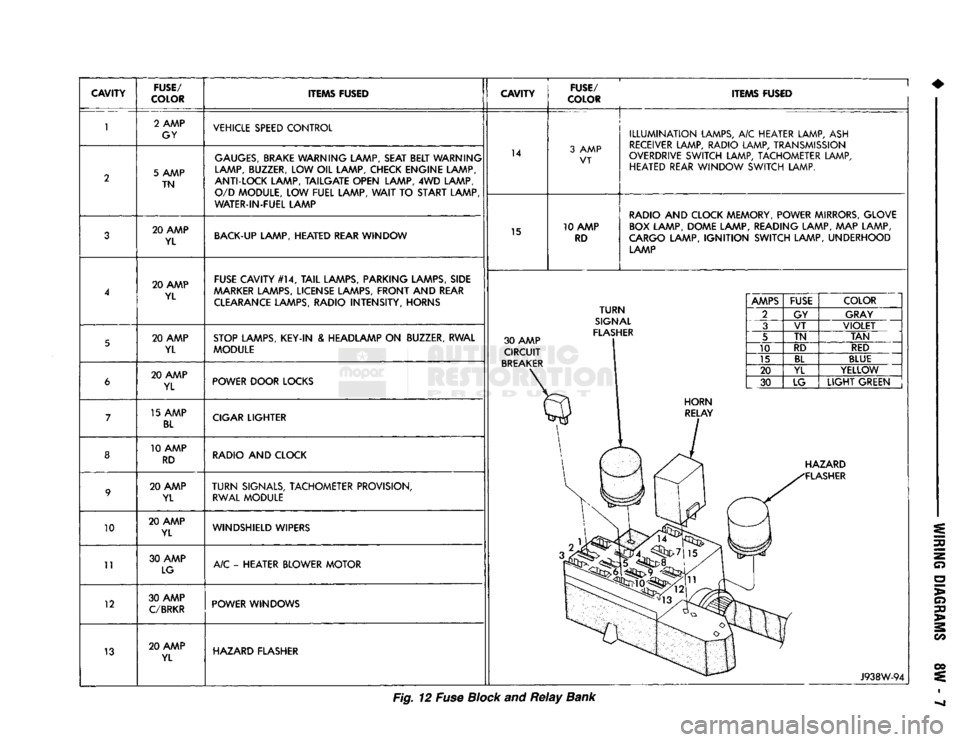
CAVITY
FUSE/
COLOR ITEMS FUSED
CAVITY
FUSE/
COLOR ITEMS FUSED
10
11
12
13 2 AMP
GY VEHICLE SPEED CONTROL
5 AMP TN
GAUGES,
BRAKE WARNING LAMP, SEAT BELT WARNING
LAMP, BUZZER, LOW OIL LAMP, CHECK ENGINE LAMP,
ANTI-LOCK LAMP, TAILGATE OPEN LAMP, 4WD LAMP, O/D MODULE, LOW FUEL LAMP,
WAIT
TO START LAMP
WATER-IN-FUEL LAMP 14
3 AMP
VT
20 AMP YL BACK-UP LAMP, HEATED REAR WINDOW
15 10 AMP
RD
ILLUMINATION
LAMPS, A/C HEATER LAMP, ASH
RECEIVER LAMP, RADIO LAMP, TRANSMISSION
OVERDRIVE SWITCH LAMP, TACHOMETER LAMP, HEATED REAR WINDOW SWITCH LAMP.
RADIO AND CLOCK MEMORY, POWER MIRRORS, GLOVE BOX LAMP, DOME LAMP, READING LAMP, MAP LAMP,
CARGO LAMP,
IGNITION
SWITCH LAMP, UNDERHOOD LAMP
20 AMP YL FUSE CAVITY #14,
TAIL
LAMPS, PARKING LAMPS, SIDE
AAARKER
LAMPS, LICENSE LAMPS, FRONT AND REAR CLEARANCE LAMPS, RADIO INTENSITY, HORNS
20 AMP YL STOP LAMPS, KEY-IN & HEADLAMP ON BUZZER, RWAL
MODULE 30 AMP
CIRCUIT
BREAKER
TURN
SIGNAL
FLASHER 20 AMP
YL POWER DOOR LOCKS
15 AMP
BL
CIGAR LIGHTER
10 AMP RD RADIO AND CLOCK
20 AMP YL
TURN
SIGNALS, TACHOMETER PROVISION,
RWAL MODULE
20 AMP YL WINDSHIELD WIPERS
30 AMP LG A/C - HEATER BLOWER MOTOR
30 AMP
C/BRKR
POWER WINDOWS
20 AMP YL HAZARD FLASHER
AMPS
FUSE
COLOR
2 GY GRAY
3 VT
VIOLET
5 TN
TAN
10 RD
RED
15
BL
BLUE
20 YL YELLOW
30 LG
LIGHT
GREEN HAZARD
FLASHER
J938W-94
Fig. 12 Fuse Block and
Relay
Bank