air condition DODGE TRUCK 1993 Service Repair Manual
[x] Cancel search | Manufacturer: DODGE, Model Year: 1993, Model line: TRUCK, Model: DODGE TRUCK 1993Pages: 1502, PDF Size: 80.97 MB
Page 1487 of 1502
25-10
EMISSION
CONTROL
SYSTEMS
EXHAUST
EMISSION
CONTROLS
INDEX
page
Air Inlet—5.9L Diesel
Engine
13
Exhaust
Gas Recirculation (EGR)
Systems
10
HEATED
INLET
AIR
SYSTEM
The air filter housing mounted-heated inlet air sys
tem is no longer used on any Dodge Truck gas pow ered engine.
EXHAUST
GAS
RECIRCULATION
(EGR)
SYSTEMS
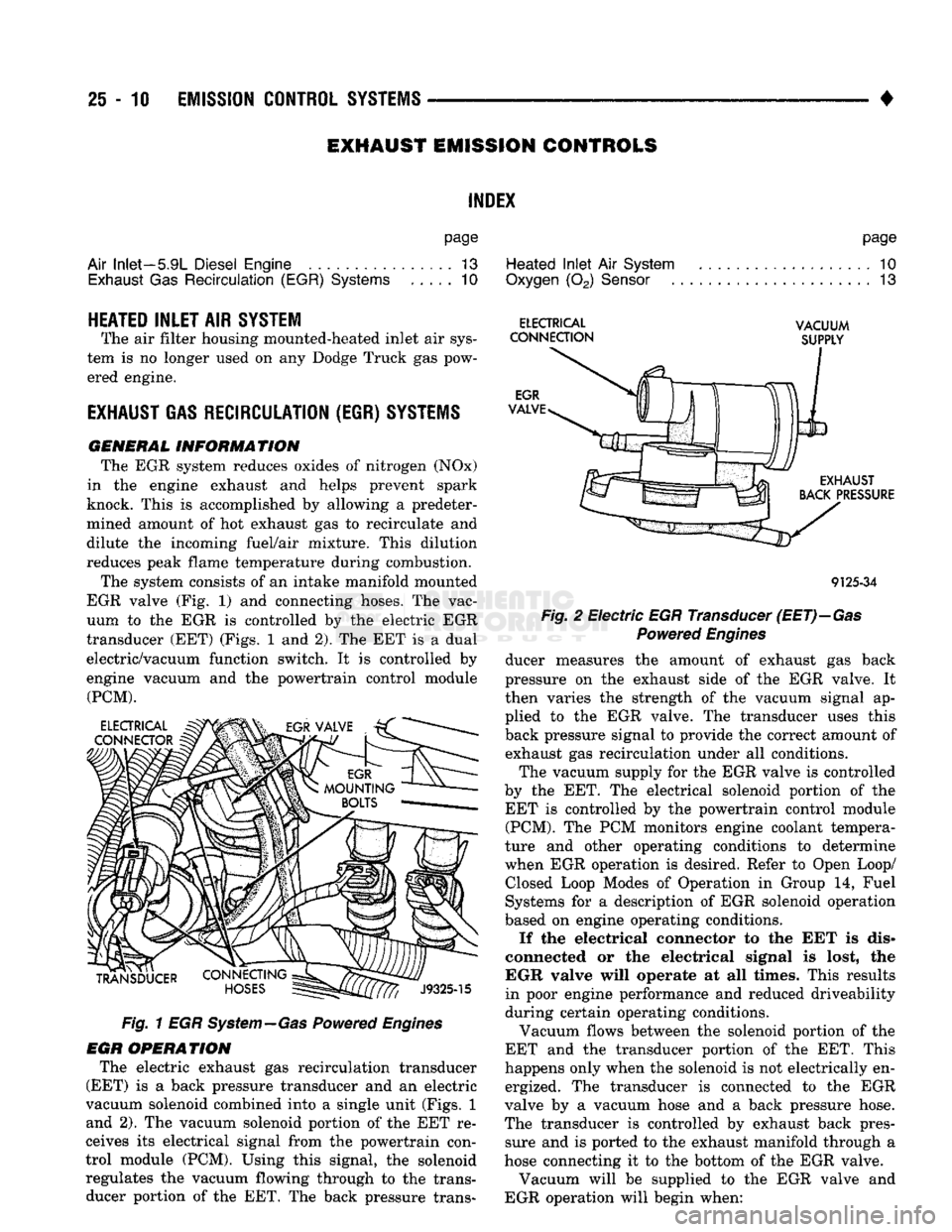
GENERAL INFORMATION The EGR system reduces oxides of nitrogen (NOx)
in the engine exhaust and helps prevent spark
knock. This is accomplished by allowing a predeter
mined amount of hot exhaust gas to recirculate and
dilute the incoming fuel/air mixture. This dilution
reduces peak flame temperature during combustion.
The system consists of an intake manifold mounted
EGR valve (Fig. 1) and connecting hoses. The vac
uum to the EGR is controlled by the electric EGR
transducer (EET) (Figs. 1 and 2). The EET is a dual
electric/vacuum function switch. It is controlled by
engine vacuum and the powertrain control module (PCM).
Fig. 1 EGR System—Gas Powered Engines
EGR OPERATION The electric exhaust gas recirculation transducer
(EET) is a back pressure transducer and an electric
vacuum solenoid combined into a single unit (Figs. 1 and 2). The vacuum solenoid portion of the EET re
ceives its electrical signal from the powertrain con
trol module (PCM). Using this signal, the solenoid regulates the vacuum flowing through to the trans ducer portion of the EET. The back pressure trans-
page
Heated
Inlet
Air
System
. 10
Oxygen
(02)
Sensor
13
ELECTRICAL
VACUUM
CONNECTION
SUPPLY
9125-34
Fig.
2 Electric EGR Transducer
(EET)—Gas
Powered
Engines
ducer measures the amount of exhaust gas back
pressure on the exhaust side of the EGR valve. It
then varies the strength of the vacuum signal ap
plied to the EGR valve. The transducer uses this
back pressure signal to provide the correct amount of exhaust gas recirculation under all conditions.
The vacuum supply for the EGR valve is controlled
by the EET. The electrical solenoid portion of the EET is controlled by the powertrain control module (PCM). The PCM monitors engine coolant tempera
ture and other operating conditions to determine
when EGR operation is desired. Refer to Open Loop/ Closed Loop Modes of Operation in Group 14, Fuel
Systems for a description of EGR solenoid operation
based on engine operating conditions.
If the electrical connector to the EET is dis
connected or the electrical signal is lost, the
EGR valve will operate at all times. This results
in poor engine performance and reduced driveability
during certain operating conditions.
Vacuum flows between the solenoid portion of the
EET and the transducer portion of the EET. This
happens only when the solenoid is not electrically en ergized. The transducer is connected to the EGR
valve by a vacuum hose and a back pressure hose.
The transducer is controlled by exhaust back pres sure and is ported to the exhaust manifold through a
hose connecting it to the bottom of the EGR valve.
Vacuum will be supplied to the EGR valve and
EGR operation will begin when:
Page 1488 of 1502
•
EMISSION
CONTROL
SYSTEMS
25 - 11 • The electrical solenoid portion of the EET is not
energized.
• The engine back pressure entering the EGR valve
inlet is strong enough to close the transducer bleed
valve.
If back pressure is not strong enough to close the
transducer bleed valve, the transducer will bleed off the vacuum preventing EGR operation.
When the electrical solenoid portion of the EET is
de-energized by the powertrain control module (PCM), vacuum flows to the transducer. The trans
ducer is connected to the engine exhaust system by a small hose that connects to the base of the EGR
valve.
The vacuum section of the transducer is controlled
by exhaust system back pressure. When back pres sure is high enough it will close a bleed valve in the
transducer allowing vacuum to actuate the EGR
valve. If back pressure does not close the bleed valve,
vacuum will be bled off.
For more information, refer to Group 14, Fuel Sys
tems.
Refer to the Component Removal/Installation sec
tion of this group for EGR valve replacement proce
dures.
EGR SYSTEM ON-BOARD DIAGNOSTICS
(CALIFORNIA VEHICLES
ONLY)
The powertrain control module (PCM) performs an
On-Board Diagnostic (OBD) check of the EGR system
on all California vehicles. The diagnostic system uses
the electric EGR transducer (EET) for the system
tests.
The OBD check activates only during selected en
gine/driving conditions. When the conditions are met,
the PCM energizes the EET solenoid to disable the EGR. The PCM checks for a change in the oxygen sensor signal. If the air-fuel mixture goes lean, the
PCM will attempt to enrichen the mixture. The PCM
registers a diagnostic trouble code (DTC) if the EGR system has failed or degraded. After registering a
DTC,
the PCM turns the malfunction indicator
lamp (MIL) on. (The malfunction indicator lamp was formerly referred to as the check engine lamp). The
malfunction indicator lamp indicates the need for im
mediate service.
If a malfunction is indicated by the malfunction in
dicator lamp and a DTC for the EGR system was set,
check for proper operation of EGR system. Use the
following: System Test, EGR Gas Flow Test and EGR
Diagnosis Chart.
If the EGR system tests properly, check the system
using the DRB II scan tool. For use of the DRB II,
refer to the appropriate Powertrain Diagnostics Pro cedure service manual. EGR SYSTEM SERVICE
A malfunctioning EGR system can cause engine
spark knock, sags or hesitation, rough idle, engine
stalling and poor driveability. To be sure of proper
operation of the EGR system, inspect all passages for
blockage. Check moving parts for binding. Inspect
the complete system for leaks. Replace system com ponents or hoses that are leaking.
Inspect all hose connections between throttle body,
intake manifold, EGR valve and EGR purge solenoid.
Replace any vacuum harness components that are
leaking or damaged. Refer to EGR Control System Test and EGR Gas
Flow Test to check EGR System operation.
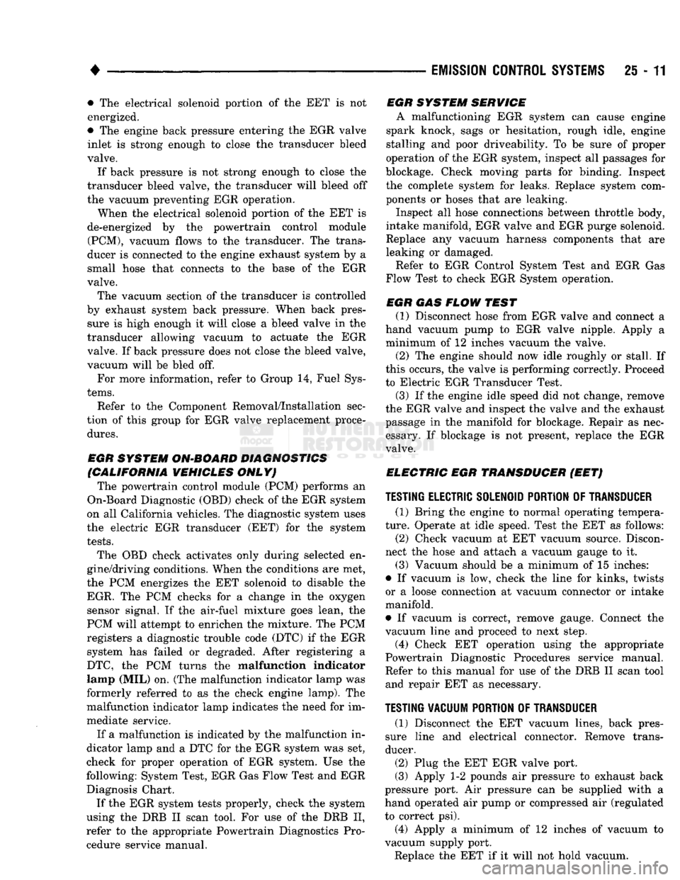
EGR GAS FLOW TEST (1) Disconnect hose from EGR valve and connect a
hand vacuum pump to EGR valve nipple. Apply a
minimum of 12 inches vacuum the valve.
(2) The engine should now idle roughly or stall. If
this occurs, the valve is performing correctly. Proceed
to Electric EGR Transducer Test.
(3) If the engine idle speed did not change, remove
the EGR valve and inspect the valve and the exhaust passage in the manifold for blockage. Repair as nec
essary. If blockage is not present, replace the EGR
valve.
ELECTRIC EGR TRANSDUCER (EET)
TESTING ELECTRIC SOLENOID PORTION OF TRANSDUCER
(1) Bring the engine to normal operating tempera
ture.
Operate at idle speed. Test the EET as follows: (2) Check vacuum at EET vacuum source. Discon
nect the hose and attach a vacuum gauge to it.
(3) Vacuum should be a minimum of 15 inches:
• If vacuum is low, check the line for kinks, twists
or a loose connection at vacuum connector or intake
manifold.
• If vacuum is correct, remove gauge. Connect the
vacuum line and proceed to next step. (4) Check EET operation using the appropriate
Powertrain Diagnostic Procedures service manual.
Refer to this manual for use of the DRB II scan tool and repair EET as necessary.
TESTING VACUUM PORTION
OF
TRANSDUCER
(1) Disconnect the EET vacuum lines, back pres
sure line and electrical connector. Remove trans
ducer.
(2) Plug the EET EGR valve port.
(3) Apply 1-2 pounds air pressure to exhaust back
pressure port. Air pressure can be supplied with a
hand operated air pump or compressed air (regulated
to correct psi).
(4) Apply a minimum of 12 inches of vacuum to
vacuum supply port.
Replace the EET if it will not hold vacuum.
Page 1489 of 1502

25
- 12
EMISSION
CONTROL
SYSTEMS
EGR
DIAGNOSIS
CHART
NOTE: ALL TESTS MUST BE MADE
WITH
FULLY
WARM ENGINE RUNNING CONTINUOUSLY FOR
AT
LEAST TWO MINUTES
WARNING: BE SURE
TO
APPLY PARKING BRAKE AND/OR BLOCK WHEELS BEFORE PERFORMING IDLE CHECK
OR
ADJUSTMENT,
OR ANY
ENGINE RUNNING TESTS
OR
ADJUSTMENTS.
Condition
Possible Cause
Correction
EGR
VALVE STEM
DOES
NOT MOVE
ON
SYSTEM
TEST.
(a) Cracked, leaking, disconnected or
plugged hoses.
EGR
VALVE STEM
DOES
NOT MOVE
ON
SYSTEM
TEST.
OPERATES
NORMALLY
ON EXTERNAL
VACUUM
SOURCE.
ENGINE
WILL
NOT
IDLE.
DIES OUT
ON
RETURN
TO
IDLE
OR
IDLE
IS
VERY ROUGH
OR SLOW.
(a) Defective control system—Plugged passages.
(b) Defective control system—solenoid or solenoid control circuit,
(a) High EGR valve leakage in closed
position.
(b) EGR tube to intake manifold leak.
(c) Solenoid or control signal to solenoid failure. (a)
(b)
(a)
(b)
(a) Verify correct hose connections and leak
check and confirm that alt hoses are open.
If defective hoses are found, replace hose
harness.
Disconnect hose harness from EGR vacuum
transducer and connect auxiliary vacuum supply. Raise engine rpm to 2000 rpm and hold. Apply 10" Hg vacuum while checking
valve movement. If no valve movement oc
curs,
replace valve/transducer assy. If valve
opens (approx. 3mm or 1/8" travel), hold
supply vacuum to check for diaphragm
leakage. Valve should remain open 30
seconds or longer. If leakage occurs, replace
valve/transducer assy. If valve is satisfac
tory, check control system. Remove throttle body and inspect port (slot
type) in throttle bore and associated passage in throttle body. Use suitable sol
vent to remove deposits and check for flow
with light air pressure. Normal operation
should be restored to EGR system. Refer to Group 14. General Diagnosis "On
Board Diagnostics" to check solenoid.
If removal of vacuum hose from EGR valve
does not correct rough idle,
(a
1)
Turn
engine off. Remove the air cleaner ex posing the inlet to the throttle body.
(a2) Disconnect the backpressure hose from the EGR valve.
(a3) Using a nozzle with a rubber grommet con nection, direct compressed air (50 to 60 psi)
down through the steel backpressure tube on
the EGR valve while opening and closing the
throttle blade.
(a4) If the sound from the compressed air changes distinctly in step a3, the poppet is leaking
and air is entering the intake manifold. Replace the EGR valve.
Remove tube and visually inspect tube seal
on gasket. Tube end should be uniformally
indented on gasket with no signs of leak. If
signs of exhaust gas leakage are present, replace gaskets and tighten flange nuts to
23 N-m (200 in. lbs.). If an intake plenum
leak persists, replace EGR tube and gaskets,
following installation instructions.
Verify correct hose connections and leak
check and confirm that all hoses are open. If defective hoses are found, replace nose
harness.
(cl) Refer to Group 14, General Diagnosis "On Board Diagnostics" to check solenoid. (b)
(c)
NOTE:
DO
NOT
ATTEMPT
TO CLEAN BACK-PRESSURE EGR VALVE, REPLACE
ENTIRE VALVE/TRANSDUCER ASSEMBLY
IF
NECESSARY.
9225-26
Page 1492 of 1502
•
EMISSION
CONTROL
SYSTEMS
25 - 15
AIR INJECTION SYSTEM—5.9L
HDC-GAS
ENGINE
INDEX
page
Air
Injection
Pump
15
Check
Valve—Air
Injection
Tube 16 General
Information
page
. . 15
GENERAL
INFORMATION
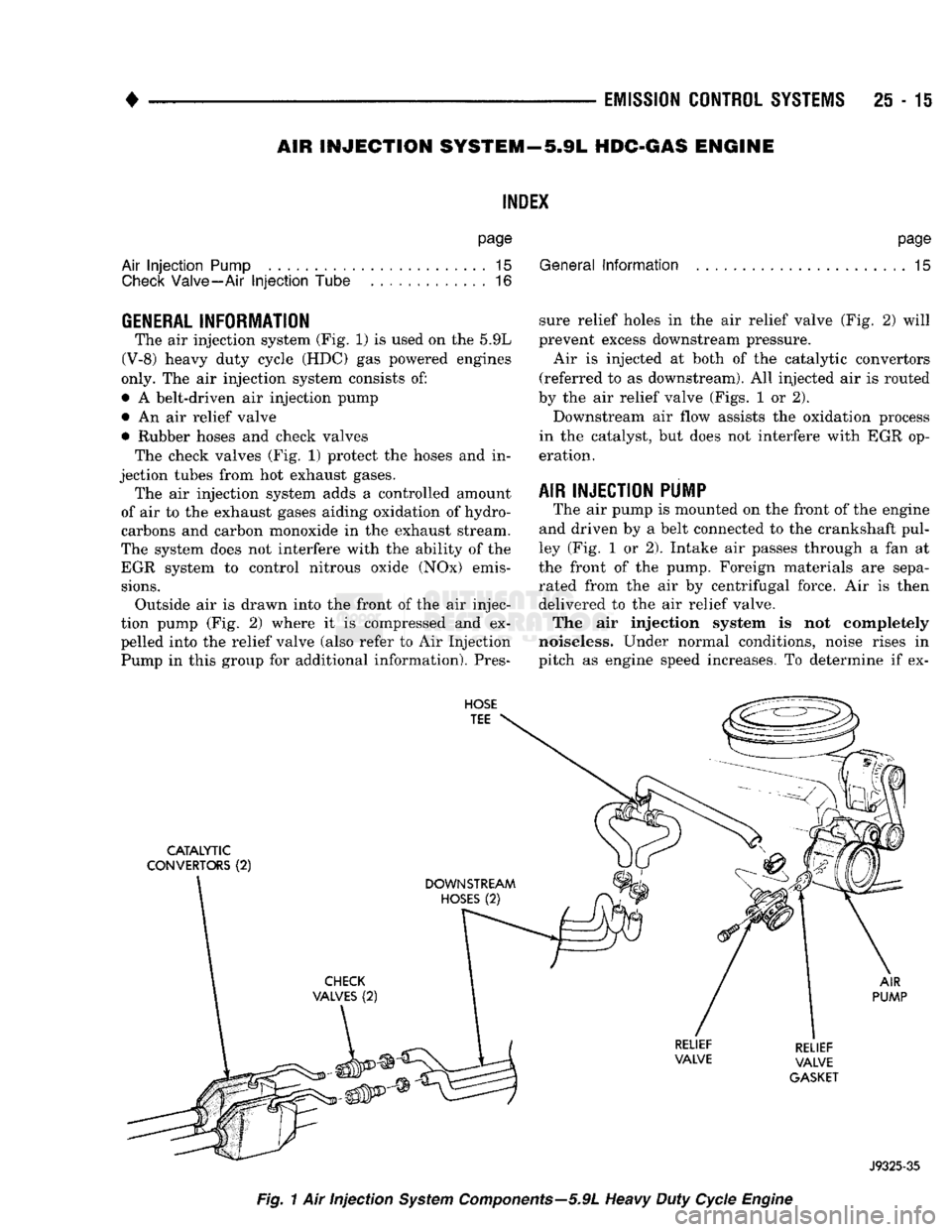
The air injection system (Fig. 1) is used on the 5.9L
(V-8) heavy duty cycle (HDC) gas powered engines
only. The air injection system consists of:
• A belt-driven air injection pump • An air relief valve
• Rubber hoses and check valves The check valves (Fig. 1) protect the hoses and in
jection tubes from hot exhaust gases. The air injection system adds a controlled amount
of air to the exhaust gases aiding oxidation of hydro
carbons and carbon monoxide in the exhaust stream.
The system does not interfere with the ability of the EGR system to control nitrous oxide (NOx) emis
sions.
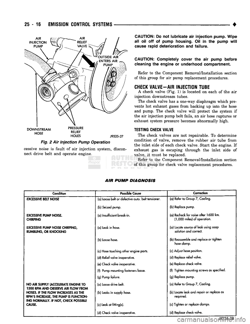
Outside air is drawn into the front of the air injec
tion pump (Fig. 2) where it is compressed and ex
pelled into the relief valve (also refer to Air Injection Pump in this group for additional information). Pres sure relief holes in the air relief valve (Fig. 2) will
prevent excess downstream pressure.
Air is injected at both of the catalytic convertors
(referred to as downstream). All injected air is routed
by the air relief valve (Figs. 1 or 2).
Downstream air flow assists the oxidation process
in the catalyst, but does not interfere with EGR op eration.
AIR INJECTION PUMP
The air pump is mounted on the front of the engine
and driven by a belt connected to the crankshaft pul
ley (Fig. 1 or 2). Intake air passes through a fan at
the front of the pump. Foreign materials are sepa rated from the air by centrifugal force. Air is then
delivered to the air relief valve.
The air injection system is not completely
noiseless. Under normal conditions, noise rises in
pitch as engine speed increases. To determine if ex-
HOSE
TEE
CATALYTIC
CONVERTORS
(2)
AIR
PUMP
RELIEF
VALVE
GASKET
J9325-35
Fig.
1 Air injection
System
Components—5.9L
Heavy
Duty
Cycle
Engine
Page 1493 of 1502
25 - 16
EMISSION
CONTROL
SYSTEMS
•
DOWNSTREAM
dciicc
HOSE
RELIEF
HOLES
J9325-37
Fig.
2 Air Injection
Pump
Operation cessive noise is fault of air injection system, discon
nect drive belt and operate engine.
CAUTION:
Do not lubricate air injection pump. Wipe
all oil off of pump
housing.
Oil in the pump
will
cause
rapid deterioration and failure.
CAUTION:
Completely cover the air pump before
cleaning
the engine or underhood compartment. Refer to the Component Removal/Installation section
of this group for air pump replacement procedures.
CHECK
VALVE—AIR
INJECTION
TUBE
A check valve (Fig. 1) is located on each of the air
injection downstream tubes. The check valve has a one-way diaphragm which pre
vents hot exhaust gases from backing up into the hose and pump. The check valve will protect the system if
the air injection pump belt fails, an air hose ruptures or exhaust system pressure becomes abnormally high.
TESTING
CHECK
VALVE
The check valves are not repairable. To determine
condition of valve, remove the rubber air tube from
the inlet side of each check valve. Start the engine. If
exhaust gas is escaping through the inlet side of
valve, it must be replaced.
Refer to the Component Removal/Installation section
of this group for check valve replacement procedures.
AIR
PUMP
DIAGNOSIS
Condition
Possible
Cause
Correction
EXCESSIVE
BELT
NOISE
(a)
Loose
belt
or defective auto,
belt
tensioner. (a) Refer to
Group
7,
Cooling.
(b) Seized pump. (b) Replace pump.
EXCESSIVE
PUMP
NOISE.
CHIRPING
(a) Insufficient break-in.
(a) Recheck for
noise
after
1600 km.
(1,000
miles) of operation.
EXCESSIVE
PUMP
NOISE CHIRPING,
RUMBUNG, OR KNOCKING (a) Leak in
hose.
(a) Locate
source
of leak
using
soap
solution
and correct.
(b)
Loose
hose.
(b)
Reassemble
and replace or tighten
hose
clamp.
(c)
Hose
touching other engine parts. (c) Adjust
hose
position.
(d) Relief valve inoperative. (d) Replace
relief
valve.
(e) Check valve inoperative. (e) Replace check valve.
(f)
Pump
mounting fasteners
loose.
(f) Tighten mounting
screws
as specified.
(g)
Pump
failure.
(g)
Replace pump.
NO AIR SUPPLY (ACCELERATE ENGINE TO 1500 RPM AND OBSERVE AIR
FLOW
FROM
HOSES.
IF THE
FLOW
INCREASES
AS
THE
RPM'S
INCREASE, THE
PUMP
IS
FUNCTION
ING NORMALLY. IF NOT, CHECK POSSIBLE
CAUSE.
(a)
Loose
drive belt.
(b)
Leaks
in
supply
hose.
(c) Leak at fitting(s). (a) Refer to
Group
7,
Cooling.
(b) Locate leak and repair or replace as required.
(c) Tighten or replace
clamps.
(d) Check valve inoperative. (d) Replace check valve.
J9325-38
Page 1494 of 1502

•
EMISSION
CONTROL SYSTEMS
25 - 17
COMPONENT REMOVAL/INSTALLATION
INDEI
page
Air
Filter/Filter
Housing—Diesel Engines
17
Air
Filter/Filter
Housing—Gas Engines
17
Air
Injection
Pump
17
Air
Injection
Pump Relief Valve
18
Check
Valve—Air
Injection
Tube
18
Coolant Temperature
Sensor
. 18
EGR
Tube—Gas Powered Engines
19
EGR
Valve
19
AIR FILTER/FILTER HOUSING-GAS ENGINES
REMOVAL/INSTALLATION Remove crankcase breather/filter hose at side of air
filter housing. Remove wingnut (Fig. 1) and remove
housing from engine. Check condition of gasket at
throttle body and replace as necessary. To replace air filter element only: Remove wingnut
and air filter housing cover (Fig. 1). Clean inside of
housing before replacing filter. Housing removal is not necessary for filter replacement.
^
WING NUT
COVER
:
GASKET
| I
MOUNTING
STUD
Fig.
1 Air
Filter
Housing—Gas
Powered
Engines—Typical
page
Electric
EGR Transducer (EET)
20
EVAP
Canister
20
EVAP
Canister Purge Solenoid
20
Fuel Tank
Filler
Tube
Cap . 21
Oxygen
(02)
Sensor
21
Powertrain Control Module (PCM)
21
Pressure
Relief/Rollover Valve
21
If housing-to-throttle body mounting stud is being
installed, tighten to 10 N»m (90 in. lbs.) torque. In stall housing to engine and tighten wingnut to 1.5
N»m (15 in. lbs.) torque.
AIR FILTER/FILTER HOUSING-DIESEL ENGINES
REMO
VAL/INSTALLA
TION Remove the hose clamp at air filter housing (Fig.
2).
Remove mounting nuts and remove air filter
housing from vehicle.
To replace air filter element only: Remove hose clamp
and hose at air filter housing inlet tube. Remove three
wingnuts and air filter housing cover (Figs. 2 and 3). Clean inside of housing before replacing filter. Housing
removal is not necessary for filter replacement.
When installing a new air filter element, push el
ement into cover. Be sure it is pushed into tabs in
back of filter housing. Install wing nuts.
If housing had been removed, install mounting
nuts and tighten to 10 N»m (95 in. lbs.) torque.
AIR INJECTION PUMP
REMOVAL (1) Remove the relief valve hose clamp (Fig. 4) and
remove hose at relief valve.
(2) Remove relief valve from air pump (two bolts)
(Fig. 4). (3) Loosen (but do not remove at this time) the
three air pump pulley mounting bolts (number 2—figure 4).
(4) Relax the automatic belt tensioner and remove
the engine accessory drive belt. Refer to Group 7, Cooling System. See Belt Removal/Installation.
(5) Remove the three air pump pulley bolts and re
move pulley from pump.
(6) Remove the two air pump mounting bolts
(number
1—figure
4) and remove pump from mount
ing bracket.
Page 1500 of 1502
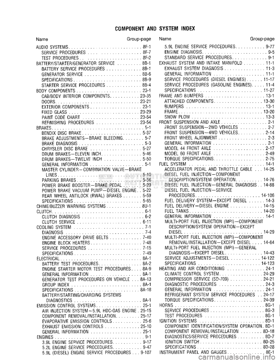
COMPONENT AND SYSTEM INDEX
Name
Group-page
AUDIO
SYSTEMS
8F-1
SERVICE
PROCEDURES 8F-7
TEST PROCEDURES 8F-2
BATTERY/STARTER/GENERATOR SERVICE 8B-1 BATTERY SERVICE PROCEDURES 8B-1
GENERATOR SERVICE 8B-6
SPECIFICATIONS 8B-9
STARTER SERVICE PROCEDURES 8B-4
BODY COMPONENTS 23-1 CAB/BODY INTERIOR COMPONENTS
23-35
DOORS
23-21
EXTERIOR COMPONENTS 23-1
FIXED GLASS
23-29
PAINT
CODE CHART
23-54
REFINISHING PROCEDURES
23-54
BRAKES
5-1 BENDIX DISC BRAKE 5-37 BRAKE ADJUSTMENTS-BRAKE BLEEDING 5-7
BRAKE DIAGNOSIS 5-3
CHRYSLER
DISC BRAKE 5-27 DRUM BRAKES—ELEVEN INCH 5-46
DRUM BRAKES-TWELVE INCH 5-50
GENERAL INFORMATION 5-1 MASTER CYLINDER—COMBINATION VALVE-BRAKE
LINES 5-10
PARKING BRAKES 5-56
POWER BRAKE BOOSTER-BRAKE PEDAL 5-20 POWER BRAKE VACUUM PUMP-DIESEL ENGINE. . 5-22
REAR
WHEEL ANTILOCK
(RWAL)
BRAKES 5-59
SPECIFICATIONS 5-65
CHIME/BUZZER WARNING
SYSTEMS
8U-1
CLUTCH 6-1 CLUTCH DIAGNOSIS 6-2 CLUTCH SERVICE 6-11
COOLING SYSTEM 7-1
DIAGNOSIS 7-4
ENGINE ACCESSORY DRIVE BELTS 7-40
ENGINE BLOCK HEATERS 7-48
SERVICE
PROCEDURES 7-15 SPECIFICATIONS 7-49
ELECTRICAL 8A-1 BATTERY TEST PROCEDURES 8A-2
ENGINE STARTER MOTOR TEST PROCEDURES.... 8A-9
GENERAL INFORMATION 8A-1
GENERATOR TEST PROCEDURES ON VEHICLE . . . 8A-13
GROUP INDEX 8A-1
SPECIFICATIONS 8A-18
BATTERY/STARTING/CHARGING
SYSTEMS
DIAGNOSTICS 8A-1
EMISSION
CONTROL
SYSTEMS.
25-1 AIR INJECTION SYSTEM—5.9L HDC-GAS ENGINE . 25-15 COMPONENT REMOVAL/INSTALLATION 25-17 EVAPORATIVE EMISSION CONTROLS 25-6
EXHAUST EMISSION CONTROLS 25-10
GENERAL INFORMATION 25-1
ENGINES 9-1 3.9L ENGINE SERVICE PROCEDURES 9-17 5.2L ENGINE SERVICE PROCEDURES 9-47
5.9L (DIESEL) ENGINE SERVICE PROCEDURES . . . 9-107
Name
Group-page
5.9L ENGINE SERVICE PROCEDURES 9-77 ENGINE DIAGNOSIS 9-5
STANDARD SERVICE PROCEDURES 9-1
EXHAUST SYSTEM AND INTAKE MANIFOLD 11-1
EXHAUST SYSTEM DIAGNOSIS 11-3
GENERAL INFORMATION 11-1
SERVICE
PROCEDURES (DIESEL ENGINES) 11-17
SERVICE
PROCEDURES (GASOLINE ENGINES) 11-4
SPECIFICATIONS 11-27
FRAME AND BUMPERS 13-1 ATTACHED COMPONENTS 13-30
BUMPERS
13-1
FRAME 13-20
SNOW PLOW 13-3
FRONT SUSPENSION AND AXLE 2-1 FRONT SUSPENSION—2WD VEHICLES 2-7
FRONT SUSPENSION—4WD VEHICLES 2-14 FRONT WHEEL ALIGNMENT 2-3
GENERAL INFORMATION 2-1 MODEL 44 FRONT AXLE 2-17
MODEL 60 FRONT AXLE 2-49
TORQUE SPECIFICATIONS 2-75
FUEL SYSTEM 14-1 ACCELERATOR PEDAL AND THROTTLE CABLE . . . 14-25
DIESEL
FUEL INJECTION—COMPONENT DESCRIPTION/SYSTEM OPERATION 14-76
DIESEL
FUEL INJECTION-GENERAL DIAGNOSIS. . 14-88
DIESEL
FUEL INJECTION-SERVICE
PROCEDURES
14-106
FUEL DELIVERY SYSTEM-EXCEPT DIESEL 14-3
FUEL DELIVERY-DIESEL ENGINE 14-15 FUEL TANKS 14-20
GENERAL INFORMATION 14-1 MULTI-PORT FUEL INJECTION (MPI)-COMPONENT DESCRIPTION/SYSTEM OPERATION-EXCEPT
DIESEL
14-29
MULTI-PORT FUEL INJECTION
(MPlj-COMPONENT
REMOVAL/INSTALLATION-EXCEPT DIESEL .... 14-64
MULTI-PORT FUEL INJECTION (MPI)—GENERAL DIAGNOSIS-EXCEPT DIESEL 14-43
SERVICE
ADJUSTMENTS-DIESEL
14-122
SPECIFICATIONS
14-123
HEATING AND AIR CONDITIONING 24-1 CLIMATE CONTROL SYSTEM
24-29
COMPRESSOR
SERVICE
(SD-709)
24-21 DIAGNOSTIC PROCEDURES 24-3
GENERAL INFORMATION 24-1 REFRIGERANT SYSTEM SERVICE PROCEDURES . . 24-17
TORQUE SPECIFICATIONS
24-39
HORNS 8G-1
SERVICE
PROCEDURES 8G-3
TEST PROCEDURES 8G-1
IGNITION
SYSTEMS
8D-1 COMPONENT IDENTIFICATION/SYSTEM OPERATION. 8D-1
COMPONENT REMOVAL/INSTALLATION 8D-18 DIAGNOSTICS/SERVICE PROCEDURES 8D-7
IGNITION
SWITCH
8D-25
SPECIFICATIONS
8D-28
INSTRUMENT PANEL AND GAUGES 8E-1