engine oil DODGE TRUCK 1993 Service Repair Manual
[x] Cancel search | Manufacturer: DODGE, Model Year: 1993, Model line: TRUCK, Model: DODGE TRUCK 1993Pages: 1502, PDF Size: 80.97 MB
Page 1493 of 1502
25 - 16
EMISSION
CONTROL
SYSTEMS
•
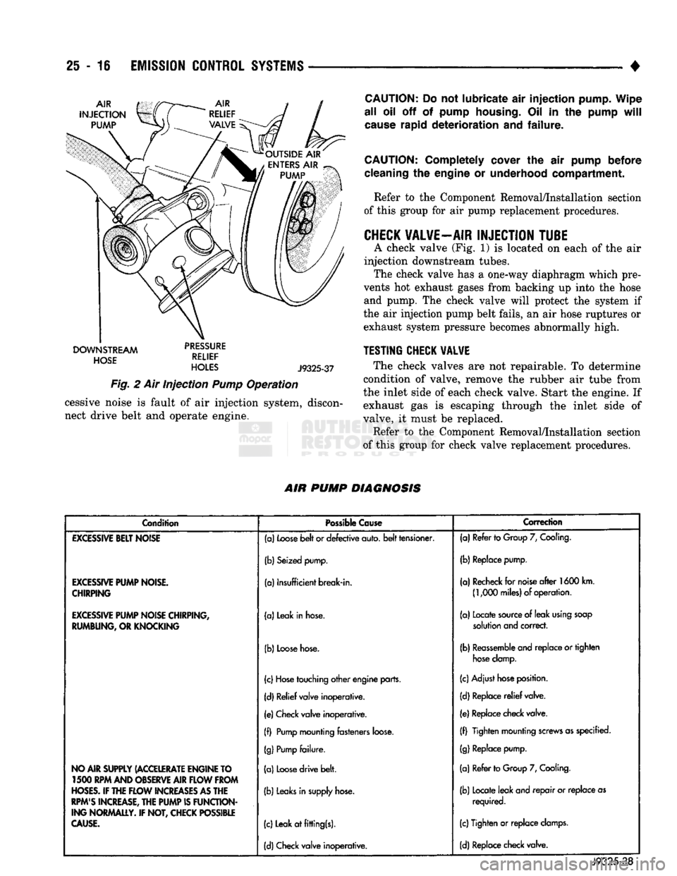
DOWNSTREAM
dciicc
HOSE
RELIEF
HOLES
J9325-37
Fig.
2 Air Injection
Pump
Operation cessive noise is fault of air injection system, discon
nect drive belt and operate engine.
CAUTION:
Do not lubricate air injection pump. Wipe
all oil off of pump
housing.
Oil in the pump
will
cause
rapid deterioration and failure.
CAUTION:
Completely cover the air pump before
cleaning
the engine or underhood compartment. Refer to the Component Removal/Installation section
of this group for air pump replacement procedures.
CHECK
VALVE—AIR
INJECTION
TUBE
A check valve (Fig. 1) is located on each of the air
injection downstream tubes. The check valve has a one-way diaphragm which pre
vents hot exhaust gases from backing up into the hose and pump. The check valve will protect the system if
the air injection pump belt fails, an air hose ruptures or exhaust system pressure becomes abnormally high.
TESTING
CHECK
VALVE
The check valves are not repairable. To determine
condition of valve, remove the rubber air tube from
the inlet side of each check valve. Start the engine. If
exhaust gas is escaping through the inlet side of
valve, it must be replaced.
Refer to the Component Removal/Installation section
of this group for check valve replacement procedures.
AIR
PUMP
DIAGNOSIS
Condition
Possible
Cause
Correction
EXCESSIVE
BELT
NOISE
(a)
Loose
belt
or defective auto,
belt
tensioner. (a) Refer to
Group
7,
Cooling.
(b) Seized pump. (b) Replace pump.
EXCESSIVE
PUMP
NOISE.
CHIRPING
(a) Insufficient break-in.
(a) Recheck for
noise
after
1600 km.
(1,000
miles) of operation.
EXCESSIVE
PUMP
NOISE CHIRPING,
RUMBUNG, OR KNOCKING (a) Leak in
hose.
(a) Locate
source
of leak
using
soap
solution
and correct.
(b)
Loose
hose.
(b)
Reassemble
and replace or tighten
hose
clamp.
(c)
Hose
touching other engine parts. (c) Adjust
hose
position.
(d) Relief valve inoperative. (d) Replace
relief
valve.
(e) Check valve inoperative. (e) Replace check valve.
(f)
Pump
mounting fasteners
loose.
(f) Tighten mounting
screws
as specified.
(g)
Pump
failure.
(g)
Replace pump.
NO AIR SUPPLY (ACCELERATE ENGINE TO 1500 RPM AND OBSERVE AIR
FLOW
FROM
HOSES.
IF THE
FLOW
INCREASES
AS
THE
RPM'S
INCREASE, THE
PUMP
IS
FUNCTION
ING NORMALLY. IF NOT, CHECK POSSIBLE
CAUSE.
(a)
Loose
drive belt.
(b)
Leaks
in
supply
hose.
(c) Leak at fitting(s). (a) Refer to
Group
7,
Cooling.
(b) Locate leak and repair or replace as required.
(c) Tighten or replace
clamps.
(d) Check valve inoperative. (d) Replace check valve.
J9325-38
Page 1496 of 1502
•
EMISSION
CONTROL SYSTEMS
25 - 19
EGR
VALVE
REMOVAL
The EGR valve and the electric EGR transducer
(EET) are serviced as one unit.
(1) Disconnect vacuum hose to EGR valve/trans
ducer assembly. Note position of hoses on EGR valve
and transducer for easier installation.
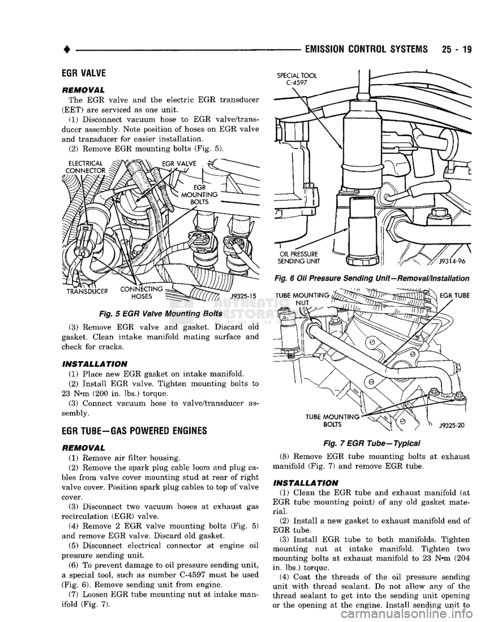
(2) Remove EGR mounting bolts (Fig. 5).
Fig.
5 EGR
Valve
Mounting
Bolts
(3) Remove EGR valve and gasket. Discard old
gasket. Clean intake manifold mating surface and
check for cracks.
INSTALLATION
(1) Place new EGR gasket on intake manifold. (2) Install EGR valve. Tighten mounting bolts to
23 N*m (200 in. lbs.) torque. (3) Connect vacuum hose to valve/transducer as
sembly.
EGR
TUBE-GAS POWERED ENGINES
REMOVAL
(1) Remove air filter housing.
(2) Remove the spark plug cable loom and plug ca
bles from valve cover mounting stud at rear of right
valve cover. Position spark plug cables to top of valve cover.
(3) Disconnect two vacuum hoses at exhaust gas
recirculation (EGR) valve. (4) Remove 2 EGR valve mounting bolts (Fig. 5)
and remove EGR valve. Discard old gasket.
(5) Disconnect electrical connector at engine oil
pressure sending unit.
(6) To prevent damage to oil pressure sending unit,
a special tool, such as number C-4597 must be used
(Fig. 6). Remove sending unit from engine.
(7) Loosen EGR tube mounting nut at intake man
ifold (Fig. 7).
Fig.
6 Oil
Pressure
Sending
Unit—Removal/Installation
Fig.
7 EGR Tube—Typical
(8) Remove EGR tube mounting bolts at exhaust
manifold (Fig. 7) and remove EGR tube.
INSTALLATION
(1) Clean the EGR tube and exhaust manifold (at
EGR tube mounting point) of any old gasket mate
rial.
(2)
Install a new gasket to exhaust manifold end of
EGR tube. (3) Install EGR tube to both manifolds. Tighten
mounting nut at intake manifold. Tighten two
mounting bolts at exhaust manifold to 23 N»m (204 in. lbs.) torque.
(4) Coat the threads of the oil pressure sending
unit with thread sealant. Do not allow any of the
thread sealant to get into the sending unit opening
or the opening at the engine. Install sending unit to