battery location DODGE TRUCK 1993 Service Owner's Guide
[x] Cancel search | Manufacturer: DODGE, Model Year: 1993, Model line: TRUCK, Model: DODGE TRUCK 1993Pages: 1502, PDF Size: 80.97 MB
Page 1048 of 1502
G360
MANUAL TRANSMISSION
21 - 47
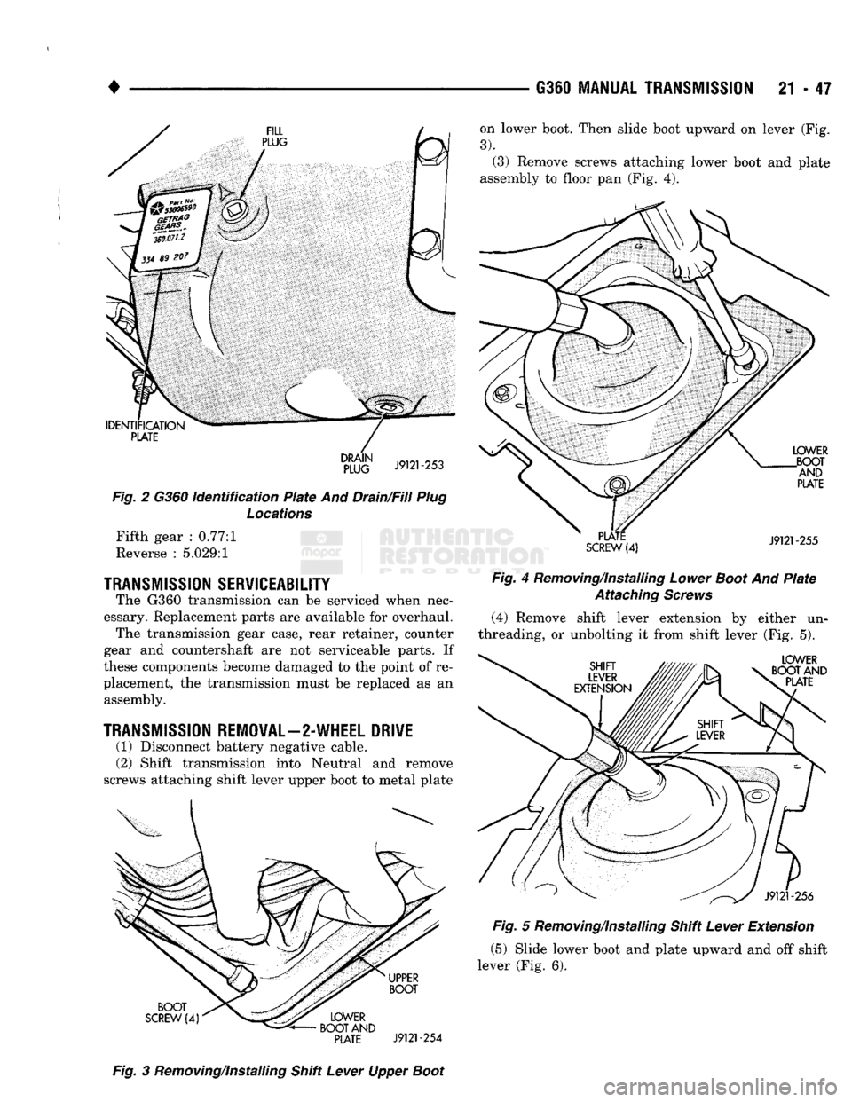
on lower boot. Then slide boot upward on lever (Fig.
3).
(3) Remove screws attaching lower boot and plate
assembly to floor pan (Fig. 4).
IDENTIFICATION
PLATE
Fig.
2 G360
identification
Plate
And Drain/Fill
Plug
Locations
Fifth gear : 0.77:1
Reverse : 5.029:1
TRANSMISSION
SERVICEABILITY
The G360 transmission can be serviced when nec
essary. Replacement parts are available for overhaul. The transmission gear case, rear retainer, counter
gear and countershaft are not serviceable parts. If
these components become damaged to the point of re
placement, the transmission must be replaced as an assembly.
TRANSMISSION
REMOVAL—2-WHEEL DRIVE
(1) Disconnect battery negative cable.
(2) Shift transmission into Neutral and remove
screws attaching shift lever upper boot to metal plate
PLATE
SCREW
(4)
LOWER
.BOOT AND
PLATE
J9121-255
Fig
4 Removing/Installing
Lower
Boot
And
Plate
Attaching
Screws
(4) Remove shift lever extension by either un
threading, or unbolting it from shift lever (Fig. 5).
LOWER
BOOT AND PLATE BOOT
SCREW
(4)
UPPER
BOOT
LOWER
BOOT AND
PLATE
J9121-254
J9121-256
Fig.
5 Removing/Installing Shift
Lever
Extension
(5) Slide lower boot and plate upward and off shift
lever (Fig. 6).
Fig.
3 Removing/Installing Shift
Lever
Upper
Boot
Page 1392 of 1502
•
BODY
COMPONENTS
23 - 9 (8) Remove the fender and the inner panel from
the cab/body.
(9) Remove the screws that attach the fender inner
panel to the fender panel. Remove the inner panel from the fender outer panel (Fig. 23).
INSTALLATION (1) Position the fender inner panel liner on the
outer panel. Install the screws. Tighten them to 23
N-m (200 in. lbs.) torque.
(2) Position the fender with inner panel on the cab/
body.
(3) Install the screws that attach the fender to the
radiator support panel. Tighten the screws to 23 N-m (200 in. lbs.) torque.
(4) Install the screws that attaches the fender and
inner panel to the dash panel. Tighten the screws to
23 N-m (200 in. lbs.) torque.
(5)
Install the screw and nut that attaches the top
of the fender to the cowl. Tighten the screw and nut
to 23 N-m (200 in. lbs.) torque. (6) If removed, install the battery and tray.
Tighten the battery tray bolts to 11 N-m (95 in. lbs.)
torque. Tighten the support bracket-to-fender inner panel bolt to 23 N-m (200 in. lbs.) torque.
(7) Install the grille extension panel and the grille.
(8) Remove the support and close the hood.
FENDER
PANEL
GRILLE
EXTENSION PANEL
J9123-565
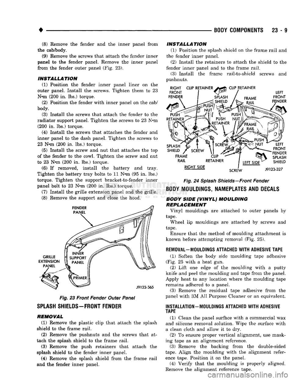
Fig.
23 Front Fender Outer Panel
SPLASH
SHIELDS—FRONT
FENDER
REMOVAL (1) Remove the plastic clip that attach the splash
shield to the frame rail. (2) Remove the pushnuts and the screws that at
tach the splash shield to the frame rail. (3) Remove the push retainers that attach the
splash shield to the fender inner panel. (4) Remove the splash shield from the frame rail
and the fender inner panel. INSTALLATION
(1) Position the splash shield on the frame rail and
the fender inner panel.
(2) Install the retainers to attach the shield to the
fender inner panel and to the frame rail. (3) Install the frame rail-to-shield screws and
pushnuts.
RIGHT
FRONT
FENDER CLIP RETAINER
CLIP RETAINER
FRAME LEFT
FRONT
FENDER
SPLASH
SHIELD
FRAME RAIL
RIGHT SIDE
SCREW
LEFT
FRONT
FENDER
SPLASH
SHIELD
J9123-327
Fig.
24
Splash
Shields—Front
Fender
BODY
MOULDINGS, NAMEPLATES AND
DECALS
BODY SIDE (VINYL) MOULDING
REPLACEMENT
Vinyl mouldings are attached to outer panels by
tape.
Wheel lip mouldings are attached by screws and
tape.
Ensure that the method of moulding attachment is
known before attempting removal (Fig. 25).
REMOVAL—MOULDINGS
ATTACHED WITH ADHESIVE TAPE
(1) Soften the body side moulding tape adhesive
(Fig. 25 with a heat gun. (2) Lift one edge of the moulding with a putty
knife and peel the moulding and tape from the panel.
Apply heat to any location where the moulding tape remains adhered to a panel.
(3) Remove the residual tape adhesive from the
panel with 3M All Purpose Cleaner or an equivalent.
INSTALLATION
—
MOULDINGS
ATTACHED WITH ADHESIVE
TAPE
(1) Clean the panel surface with a commercial wax
and silicone removal solution. Wipe the surface with
a clean cloth and allow it to dry.
(2) To ensure proper vertical alignment, use mask
ing tape as an alignment reference.
(3) Remove the backing from the double-sided
tape.
Align the moulding with the alignment refer
ence tape. Position it on the panel.
(4) Verify that the moulding is properly aligned.
Remove the alignment reference tape.