battery location DODGE TRUCK 1993 Service Owner's Manual
[x] Cancel search | Manufacturer: DODGE, Model Year: 1993, Model line: TRUCK, Model: DODGE TRUCK 1993Pages: 1502, PDF Size: 80.97 MB
Page 714 of 1502
•
5.9L
(DIESEL) ENGINE
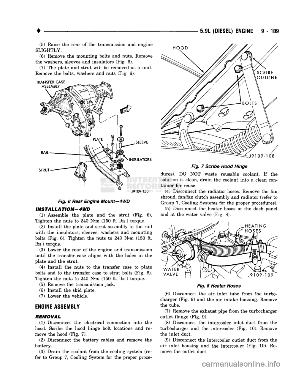
9 - 109 (5) Raise the rear of the transmission and engine
SLIGHTLY.
(6)
Remove the mounting bolts and nuts. Remove
the washers, sleeves and insulators (Fig. 6). (7) The plate and strut will be removed as a unit.
Remove the bolts, washers and nuts (Fig. 6).
J9109-150
Fig.
6 Rear
Engine
Mount—4WD
INSTALL A
TION—4
WD
(1) Assemble the plate and the strut (Fig. 6).
Tighten the nuts to 240 N-m (150 ft. lbs.) torque.
(2) Install the plate and strut assembly to the rail
with the insulators, sleeves, washers and mounting
bolts (Fig. 6). Tighten the nuts to 240 N-m (150 ft. lbs.) torque.
(3) Lower the rear of the engine and transmission
until the transfer case aligns with the holes in the
plate and the strut.
(4) Install the nuts to the transfer case to plate
bolts and to the transfer case to strut bolts (Fig. 6). Tighten the nuts to 240 N-m (150 ft. lbs.) torque.
(5) Remove the transmission jack.
(6) Install the skid plate.
(7) Lower the vehicle.
ENGINE
ASSEMBLY
REMOVAL
(1) Disconnect the electrical connection into the
hood. Scribe the hood hinge bolt locations and re
move the hood (Fig. 7).
(2) Disconnect the battery cables and remove the
battery.
(3) Drain the coolant from the cooling system (re
fer to Group 7, Cooling System for the proper proce-
Fig.
7
Scribe
Hood
Hinge
dures).
DO NOT waste reusable coolant. If the
solution is clean, drain the coolant into a clean con
tainer for reuse.
(4) Disconnect the radiator hoses. Remove the fan
shroud, fan/fan clutch assembly and radiator (refer to
Group 7, Cooling Systems for the proper procedures). (5) Disconnect the heater hoses at the dash panel
and at the water valve (Fig. 8).
Fig.
8 Heater
Hoses
(6) Disconnect the air inlet tube from the turbo
charger (Fig. 9) and the air intake housing. Remove
the tube.
(7) Remove the exhaust pipe from the turbocharger
outlet flange (Fig. 9).
(8) Disconnect the intercooler inlet duct from the
turbocharger and the intercooler (Fig. 10). Remove
the inlet duct.
(9) Disconnect the intercooler outlet duct from the
air inlet housing and the intercooler (Fig. 10). Re
move the outlet duct.
Page 849 of 1502
14
- 30
FUEL
SYSTEM
INPUTS
OUTPUTS
POWERTRAIN
CONTROL
MODULE
DRB
II
SCAN
TOOL
SPEED
CONTROL
BRAKE
SWITCH
A/C
LOW
PRESSURE
CUTOFF
SWITCH VEHICLE
SPEED
SENSOR PARK/NEUTRAL
SWITCH TORQUE CONVERTER
CLUTCH SOLENOID
MALFUNCTION
INDICATOR
LAMP
m
HEATED
i
*OXYGEN SENSOR ENGINE
COOLANT
yy
BATTERY
TEMPERATURE
SENSOR
MAP SENSOR
i—r
CHARGE
AIR
TEMPERATURE
SENSOR
AIR CHARGE
TEMPERATURE
SENSOR
DISTRIBUTOR
WITH
CAMSHAFT
r
POSITION
SENSOR
(|
TACHOMETER
A/C
CLUTCH RELAY
AUTO
SHUTDOWN
RELAY OVERDRIVE
SOLENOID
IDLE AIR
CONTROL MOTOR
SPEED
CONTROL
SHIFT
INDICATOR
LAMP
EMISSION
CONTROL SOLENOIDS
IGNITION
COIL
OVERDRIVE
OVERRIDE SWITCH
ASD
SENSE
FUEL
INJECTORS
PARK
THROTTLE
SOLENOID
GENERATOR CRANKSHAFT
POSITION FUEL
PUMP
RELAY
J9314-117
Fig.
1 Multi-Port
Fuel
Injection
Components—Except
Diesel
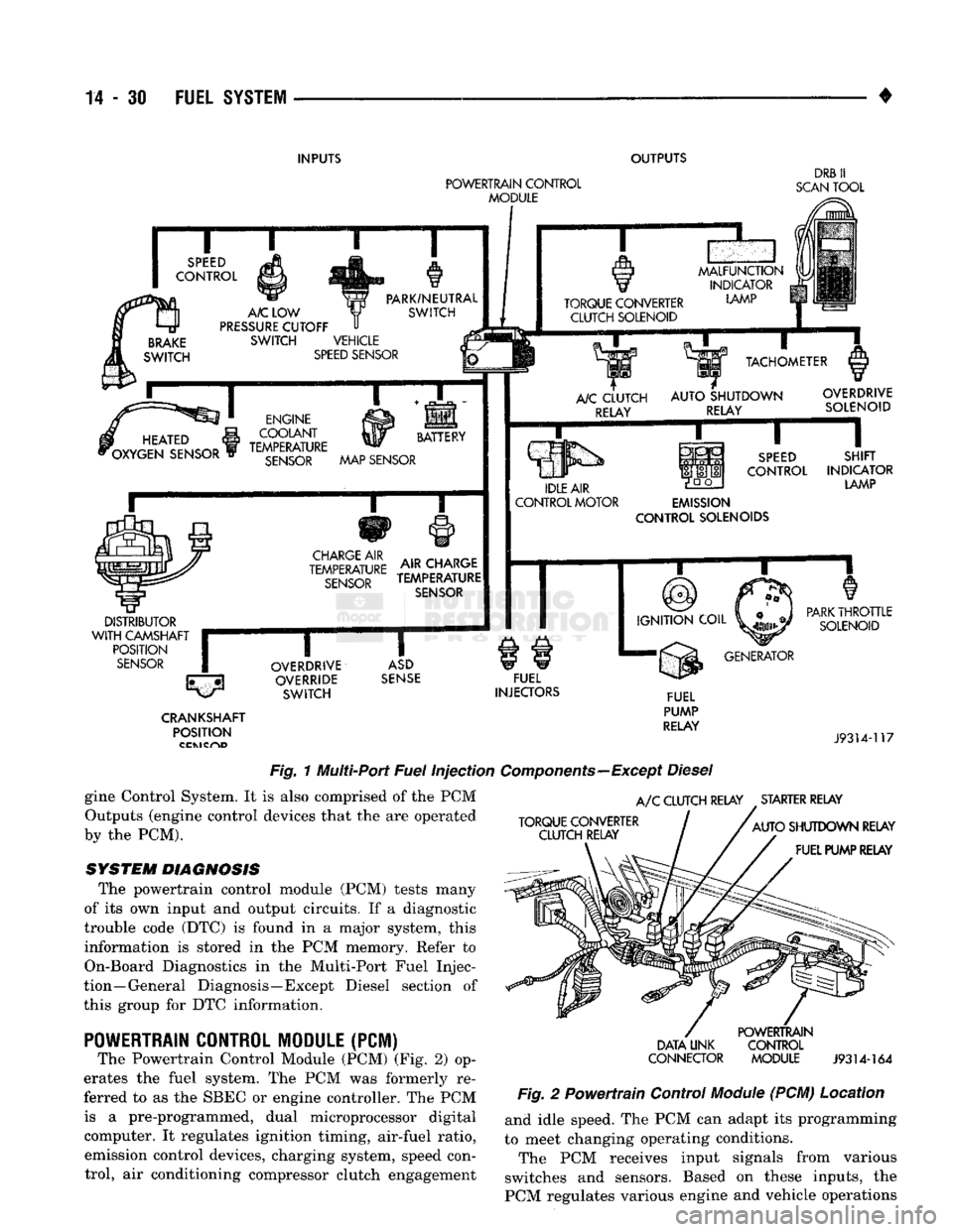
gine Control System. It is also comprised of the PCM Outputs (engine control devices that the are operated
by the PCM).
SYSTEM DIAGNOSIS
The powertrain control module (PCM) tests many
of its own input and output circuits. If a diagnostic
trouble code (DTC) is found in a major system, this information is stored in the PCM memory. Refer to
On-Board Diagnostics in the Multi-Port Fuel Injec
tion—General Diagnosis—Except Diesel section of
this group for DTC information.
POWERTRAIN
CONTROL MODULE (PCM)
The Powertrain Control Module (PCM) (Fig. 2) op
erates the fuel system. The PCM was formerly re
ferred to as the SBEC or engine controller. The PCM is a pre-programmed, dual microprocessor digital computer. It regulates ignition timing, air-fuel ratio, emission control devices, charging system, speed control, air conditioning compressor clutch engagement
A/C
CLUTCH RELAY STARTER RELAY
TORQUE CONVERTER CLUTCH RELAY
AUTO
SHUTDOWN RELAY
FUEL PUMP RELAY
DATA UNK
CONNECTOR
POWERTRAIN
CONTROL MODULE
J9314-164
Fig.
2 Powertrain Control
Module
(PCM) Location and idle speed. The PCM can adapt its programming
to meet changing operating conditions.
The PCM receives input signals from various
switches and sensors. Based on these inputs, the
PCM regulates various engine and vehicle operations
Page 862 of 1502
MULTI-PORT
FUEL
INJECTION
(MPI)—GENERAL DIAGNOSIS—EXCEPT DIESEL
INDEX
page
Camshaft Position Sensor Testing
............
52
Charge
Air
Temperature Sensor Test
52
Coolant Temperature Sensor Test
52
Crankshaft Position Sensor Test
54
Diagnostic Trouble Code (DTC)
60
DRB
II
Scan
Tool
........................
60
Fuel
Injector
Test
57
Fuel Pump Pressure Test
57
Idle
Air
Control
(IAC) Motor Test
55
Manifold Absolute Pressure (MAP) Sensor Test
. 53
page
On-Board
Diagnostics (OBD)
59
Oxygen
(02)
Sensor Heating Element Test
54
Powertrain
Control
Module (PCM) 60-Way Connector
. 47
Relays—Operation/Testing
56
Starter
Motor Relay Test
57
System
Schematics
. 47
Throttle
Position Sensor (TPS) Test
54
Visual Inspection
43
VISUAL
INSPECTION
A visual inspection
for
loose, disconnected,
or
incor
rectly routed wires
and
hoses should
be
made. This should
be
done before attempting
to
diagnose
or
ser
vice
the
fuel injection system.
A
visual check will
help spot these faults
and
save unnecessary test
and
diagnostic time.
A
thorough visual inspection will
in
clude
the
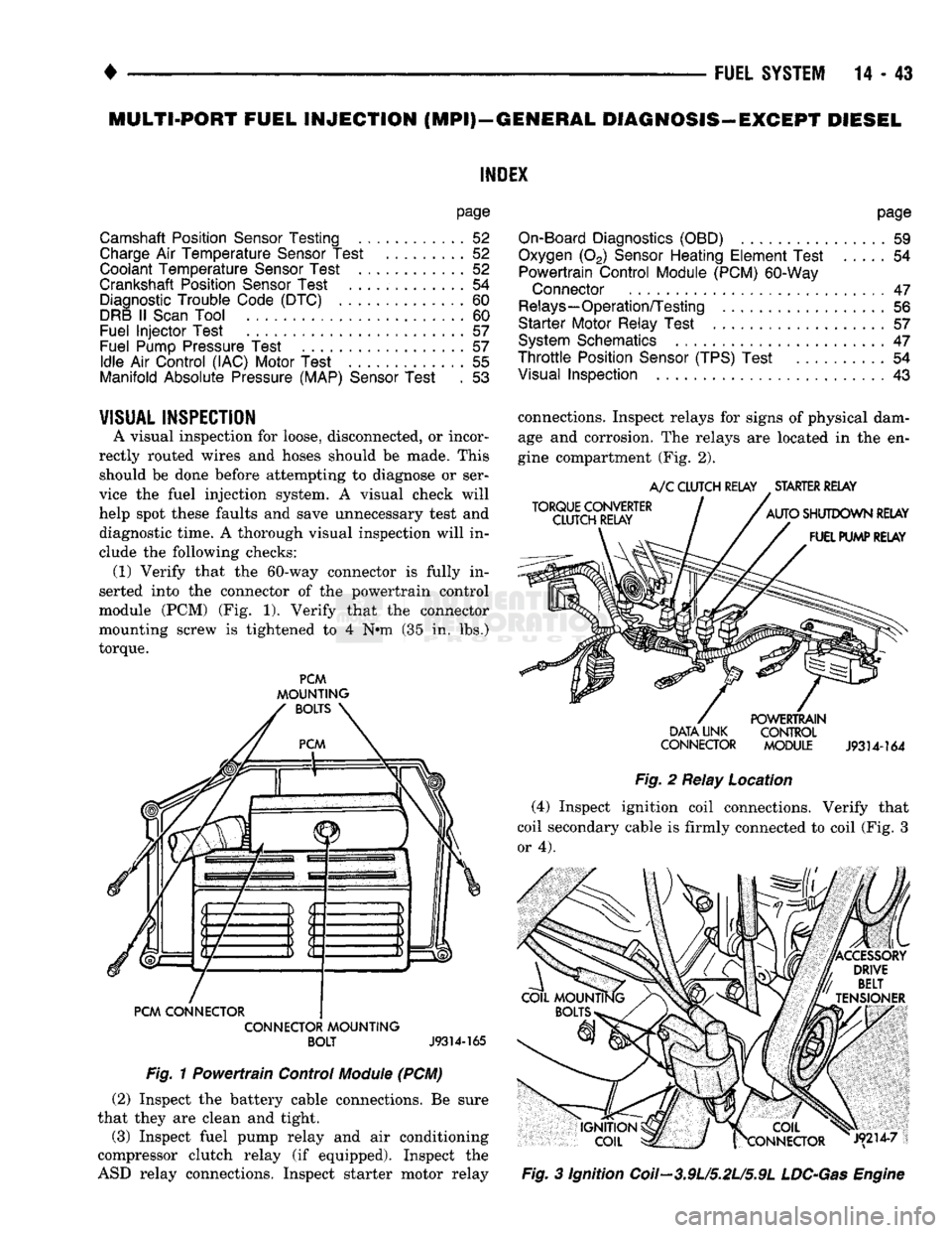
following checks: (1) Verify that
the
60-way connector
is
fully
in
serted into
the
connector
of the
powertrain control
module
(PCM) (Fig. 1).
Verify that
the
connector
mounting screw
is
tightened
to 4 N#m (35 in. lbs.)
torque.
PCM
MOUNTING
BOLTS
PCM CONNECTOR CONNECTOR MOUNTING BOLT
J9314-165
Fig.
1
Powertrain Control
Module
(PCM) (2) Inspect
the
battery cable connections.
Be
sure
that they
are
clean
and
tight.
(3) Inspect fuel pump relay
and air
conditioning
compressor clutch relay
(if
equipped). Inspect
the
ASD relay connections. Inspect starter motor relay connections. Inspect relays
for
signs
of
physical dam
age
and
corrosion.
The
relays
are
located
in the en
gine compartment
(Fig. 2).
TORQUE CONVERTER
CLUTCH RELAY
A/C
CLUTCH RELAY STARTER RELAY
AUTO SHUTDOWN RELAY FUEL PUMP RELAY POWERTRAIN
DATA UNK CONTROL
CONNECTOR MODULE
J9314-164
Fig.
2
Relay Location (4) Inspect ignition coil connections. Verify that
coil secondary cable
is
firmly connected
to
coil (Fig.
3
or 4).
|X COIL
frCONNECTOR J9214-7
Fig.
3
Ignition Coil—3.9U5.2L/5.9L
LDC-Gas
Engine
Page 865 of 1502
14
- 46
FUEL
SYSTEM
Fig.
12
Rubber
L-Shaped
Fitting—MAP
Sensor-to-
Throttie
Body
Fig.
13
Engine
Coolant
Temperature
Sensor—
Typical
EXHAUST
~~
PIPE
J9214-5
Fig.
14
Single
Oxygen
Sensor
Location-3.9U5.2L/ 5.9L LDC
Engine
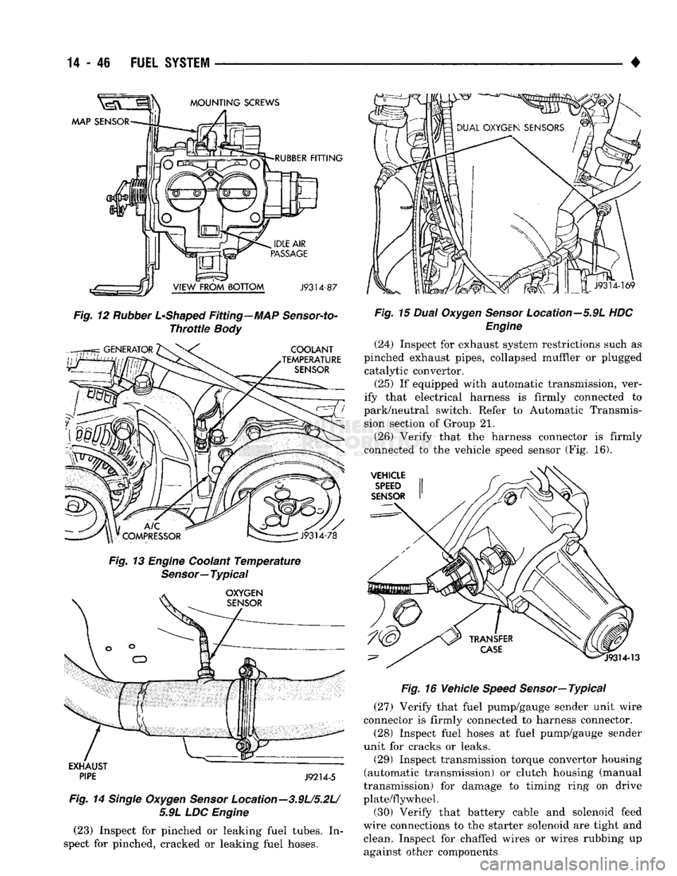
(23) Inspect for pinched or leaking fuel tubes. In
spect for pinched, cracked or leaking fuel hoses. •
Fig.
15
Dual
Oxygen
Sensor
Location—5.9L HDC
Engine
(24) Inspect for exhaust system restrictions such as
pinched exhaust pipes, collapsed muffler or plugged catalytic convertor.
(25) If equipped with automatic transmission, ver
ify that electrical harness is firmly connected to
park/neutral switch. Refer to Automatic Transmis sion section of Group 21.
(26) Verify that the harness connector is firmly
connected to the vehicle speed sensor (Fig. 16).
Fig.
16 Vehicle
Speed
Sensor—
Typical
(27) Verify that fuel pump/gauge sender unit wire
connector is firmly connected to harness connector.
(28) Inspect fuel hoses at fuel pump/gauge sender
unit for cracks or leaks.
(29) Inspect transmission torque convertor housing
(automatic transmission) or clutch housing (manual
transmission) for damage to timing ring on drive
plate/flywheel. (30) Verify that battery cable and solenoid feed
wire connections to the starter solenoid are tight and clean. Inspect for chaffed wires or wires rubbing up against other components.
Page 875 of 1502
14
- 56
FUEL
SYSTEM
• (5) Move the switch to the HIGH position. The en
gine speed should increase. Move the switch to the
LOW position. The engine speed should decrease.
(a) If the engine speed changes while using the
exerciser tool, the IAC motor is functioning prop
erly. Disconnect the exerciser tool and connect the
IAC stepper motor wire connector to the stepper motor.
(b) If the engine speed does not change, turn the
ignition OFF and proceed to step (6). Do not discon
nect exerciser from the IAC stepper motor.
(6) Remove the IAC stepper motor from the throt
tle body.
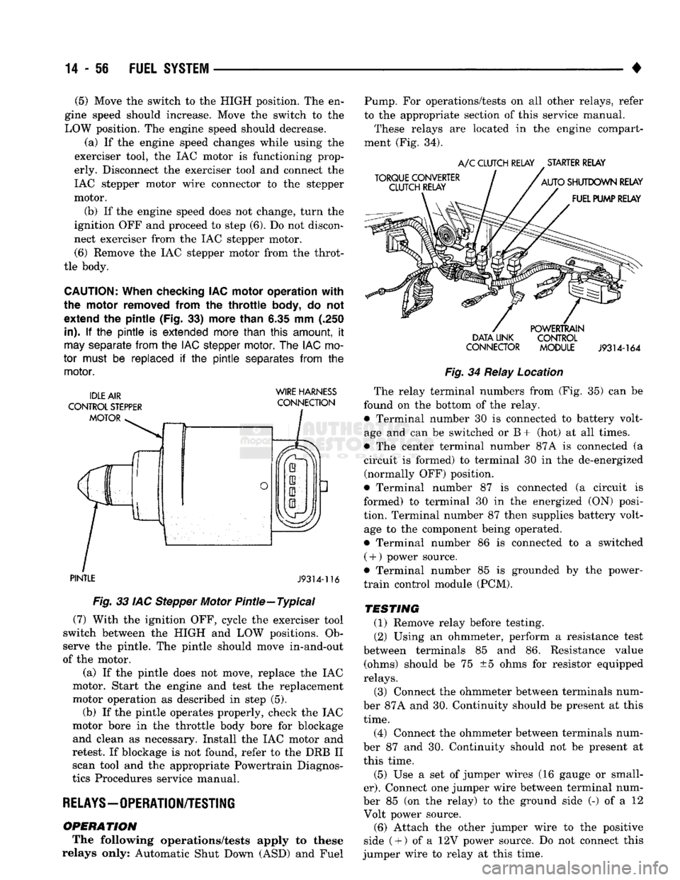
CAUTION:
When checking IAC motor operation with
the motor removed from
the
throttle
body,
do not
extend
the
pintle (Fig.
33)
more than
6.35 mm (.250
in).
If the pintle is
extended more than
this
amount,
it
may
separate
from
the
IAC stepper
motor.
The
IAC
mo
tor
must
be
replaced
if the pintle
separates
from
the
motor.
WIRE HARNESS
PINTLE
J9314-116
Fig.
33 IAC Stepper Motor Pintle—Typical (7) With the ignition OFF, cycle the exerciser tool
switch between the HIGH and LOW positions. Ob
serve the pintle. The pintle should move in-and-out
of the motor.
(a) If the pintle does not move, replace the IAC
motor. Start the engine and test the replacement
motor operation as described in step (5). (b) If the pintle operates properly, check the IAC
motor bore in the throttle body bore for blockage and clean as necessary. Install the IAC motor and
retest. If blockage is not found, refer to the DRB II scan tool and the appropriate Powertrain Diagnos
tics Procedures service manual.
RELAYS—OPERATION/TESTING
OPERATION
The following operations/tests apply to these
relays only: Automatic Shut Down (ASD) and Fuel Pump. For operations/tests on all other relays, refer
to the appropriate section of this service manual.
These relays are located in the engine compart
ment (Fig. 34).
DATA LINK CONTROL
CONNECTOR MODULE
J9314-164
Fig.
34 Relay Location The relay terminal numbers from (Fig. 35) can be
found on the bottom of the relay. • Terminal number 30 is connected to battery volt
age and can be switched or B+ (hot) at all times.
• The center terminal number 87A is connected (a
circuit is formed) to terminal 30 in the de-energized (normally OFF) position.
• Terminal number 87 is connected (a circuit is
formed) to terminal 30 in the energized (ON) posi
tion. Terminal number 87 then supplies battery volt age to the component being operated.
• Terminal number 86 is connected to a switched ( +
)
power source.
• Terminal number 85 is grounded by the power-
train control module (PCM).
TESTING
(1) Remove relay before testing. (2) Using an ohmmeter, perform a resistance test
between terminals 85 and 86. Resistance value (ohms) should be 75 ±5 ohms for resistor equipped
relays.
(3) Connect the ohmmeter between terminals num
ber 87A and 30. Continuity should be present at this
time.
(4) Connect the ohmmeter between terminals num
ber 87 and 30. Continuity should not be present at
this time.
(5) Use a set of jumper wires (16 gauge or small
er).
Connect one jumper wire between terminal num
ber 85 (on the relay) to the ground side (-) of a 12 Volt power source. (6) Attach the other jumper wire to the positive
side ( +
)
of a 12V power source. Do not connect this
jumper wire to relay at this time.
Page 892 of 1502
•
FUEL SYSTEM
14-73 (1) Install the 02 sensor into the exhaust manifold.
Tighten to 30 N*m (22 ft. lbs.) torque.
(2) Connect the 02 sensor wire connector.
(3) Lower the vehicle.
PARK/NEUTRAL
SWITCH
Refer to Group 21, Transmission and Transfer Case
for removal/installation procedures.
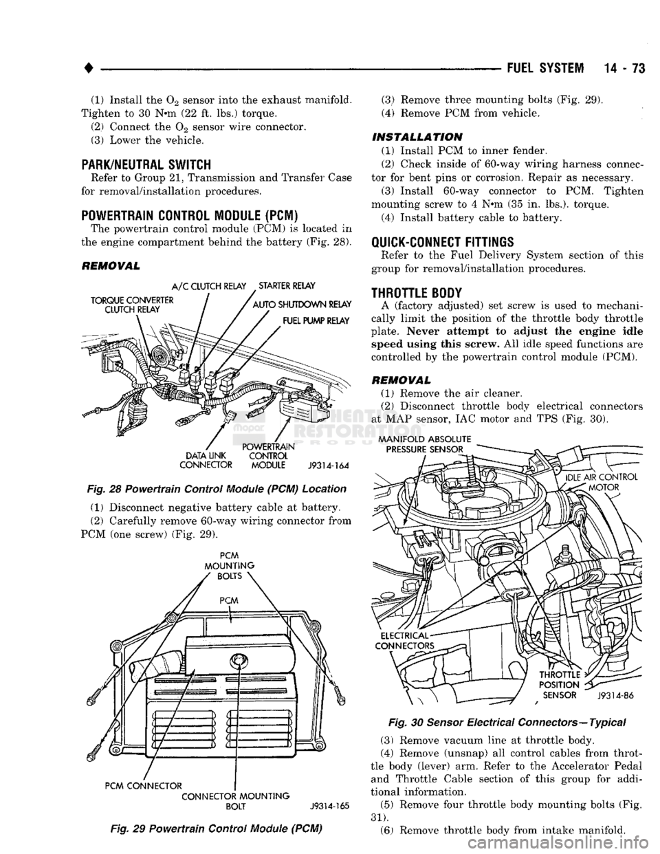
POWERTRAIN CONTROL MODULE
(PCM) The powertrain control module (PCM) is located in
the engine compartment behind the battery (Fig. 28).
REMOVAL
DATA LINK CONTROL
CONNECTOR MODULE
J9314-164
Fig.
28 Powertrain Control
Module
(PCM) Location (1) Disconnect negative battery cable at battery.
(2) Carefully remove 60-way wiring connector from
PCM (one screw) (Fig. 29).
PCM
MOUNTING
PCM CONNECTOR CONNECTOR
MOUNTING
BOLT
J9314-165
Fig.
29 Powertrain Control
Module
(PCM) (3) Remove three mounting bolts (Fig. 29).
(4) Remove PCM from vehicle.
INSTALLATION
(1) Install PCM to inner fender.
(2) Check inside of 60-way wiring harness connec
tor for bent pins or corrosion. Repair as necessary.
(3) Install 60-way connector to PCM. Tighten
mounting screw to 4 Nem (35 in. lbs.), torque.
(4) Install battery cable to battery.
QUICK-CONNECT
FITTINGS
Refer to the Fuel Delivery System section of this
group for removal/installation procedures.
THROTTLE
BODY
A (factory adjusted) set screw is used to mechani
cally limit the position of the throttle body throttle
plate. Never attempt to adjust the engine idle speed using this screw. All idle speed functions are
controlled by the powertrain control module (PCM).
REMOVAL
(1) Remove the air cleaner.
(2) Disconnect throttle body electrical connectors
at MAP sensor, IAC motor and TPS (Fig. 30).
MANIFOLD ABSOLUTE
Fig.
30
Sensor
Electrical Connectors—Typical
(3) Remove vacuum line at throttle body.
(4) Remove (unsnap) all control cables from throt
tle body (lever) arm. Refer to the Accelerator Pedal and Throttle Cable section of this group for addi
tional information.
(5) Remove four throttle body mounting bolts (Fig.
31).
(6) Remove throttle body from intake manifold.
Page 897 of 1502
14-78
FUEL SYSTEM
• If
the A/C low
pressure switch opens (indicating
a
low refrigerant level),
the PCM
will
not
receive
an
A/C select signal.
The PCM
will then remove
the
ground from
the A/C
relay. This will deactivate
the
A/C compressor clutch.
If evaporator switch opens, (indicating that evapo
rator
is not in
proper temperature range),
PCM
will
not receive
the A/C
request signal.
The PCM
will
then remove
the
ground from
the A/C
relay, deacti
vating
the A/C
compressor clutch.
AUTOMATIC SHUT DOWN
(ASD)
SENSE-PCM
INPUT
A
12
volt signal
at
this input indicates
to the PCM
that
the ASD has
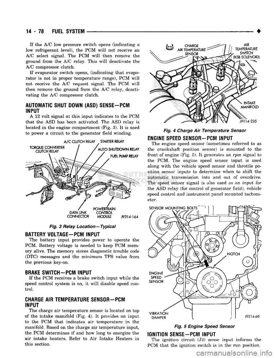
been activated.
The ASD
relay
is
located
in the
engine compartment
(Fig.
3).
It is
used
to power
a
circuit
to the
generator field winding.
TORQUE
CONVERTER
CLUTCH RELAY A/C
CLUTCH RELAY
.
STARTER RELAY
AUTO
SHUTDOWN
RELAY
FUEL PUMP RELAY
DATA
LINK
CONNECTOR
POWERTRAIN
CONTROL
MODULE
J9314-164
Fig.
3
Relay Location—Typical
BATTERY VOLTAGE-PC! INPUT
The battery input provides power
to
operate
the
PCM. Battery voltage
is
needed
to
keep
PCM
mem
ory alive.
The
memory stores diagnostic trouble code (DTC) messages
and the
minimum
TPS
value from
the previous key-on,
BRAKE
SWITCH-PCM INPUT
If
the PCM
receives
a
brake switch input while
the
speed control system
is on, it
will disable speed con
trol.
CHARGE AIR TEMPERATURE SENSOR—PCM INPUT
The charge
air
temperature sensor
is
located
on top
of
the
intake manifold
(Fig. 4). It
provides
an
input
to
the PCM
that indicates
air
temperature
in the
manifold. Based
on the
charge
air
temperature input,
the
PCM
determines
if and how
long
to
energize
the
air intake heaters. Refer
to Air
Intake Heaters
in
this section. AIR
TEMPERATURE
SWITCH
(KSB
SOLENOID)
j9114-235
Fig.
4
Charge
Air
Temperature Sensor
ENGINE
SPEED
SENSOR-PCM
INPUT
The engine speed sensor (sometimes referred
to as
the crankshaft position sensor)
is
mounted
to the
front
of
engine
(Fig. 5). It
generates
an rpm
signal
to
the
PCM. The
engine speed sensor input
is
used along with
the
vehicle speed sensor
and
throttle
po
sition sensor inputs
to
determine when
to
shift
the
automatic transmission into
and out of
overdrive.
The speed sensor signal
is
also used
as an
input
for
the
ASD
relay
(for
control
of
generator field), vehicle speed control
and
instrument panel mounted tachom
eter.
SENSOR
MOUNTING BOLTS
VIBRATION
DAMPER
J9214-69
Fig.
5
Engine Speed Sensor
IGNITION
SENSE-PCM
INPUT
The ignition circuit
(J2)
sense input informs
the
PCM that
the
ignition switch
is in the run
position.
Page 901 of 1502
14 - 82
FUEL 'SYSTEM
—. — ~—— — «
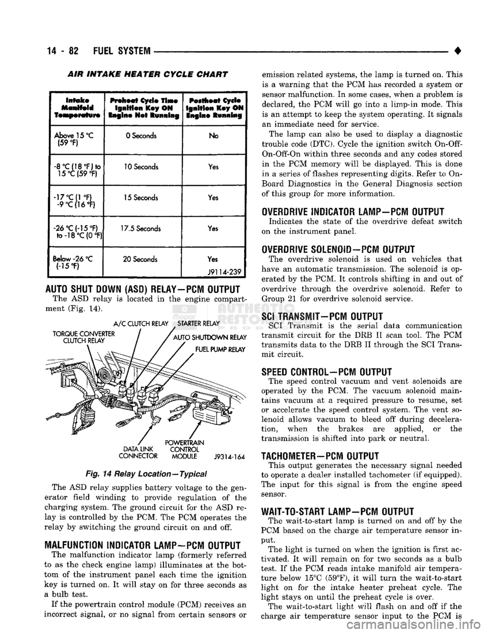
INTAKE HEATER CYCLE CHART
Intake
featperafwre
Preheat
Cycle
Time
Ignition
l£ey ON
Engine
Not
Running
Pestheat
Cycle
Ignition
Key ON
Snglne Running
Above
15
°C
(59
°F)
0 Seconds
No
-8°C(18°F)to
15°C (59
°F)
10
Seconds
Yes
-17°C(1
°F)
-9
°C(]6°F)
15
Seconds
Yes
«2d°C(-15°F)
to-18°C(0
°F) 17.5
Seconds
Yes
Below-26
°C (-15
*F)
20 Seconds
Yes
J9114-239
AUTO SHUT DOWN (ASD) RELAY-PCM OUTPUT
The ASD relay is located in the engine compart
ment (Fig. 14).
TORQUE CONVERTER
CLUTCH RELAY A/C CLUTCH RELAY STARTER RELAY
AUTO SHUTDOWN RELAY FUEL PUMP RELAY DATA LINK
CONNECTOR
POWERTRAIN
CONTROL MODULE
J9314-164
Fig.
14 Relay Location—Typical The ASD relay supplies battery voltage to the gen
erator field winding to provide regulation of the
charging system. The ground circuit for the ASD re
lay is controlled by the PCM. The PCM operates the
relay by switching the ground circuit on and off.
MALFUNCTION INDICATOR LAMP-PCM OUTPUT
The malfunction indicator lamp (formerly referred
to as the check engine lamp) illuminates at the bot
tom of the instrument panel each time the ignition
key is turned on. It will stay on for three seconds as
a bulb test. If the powertrain control module (PCM) receives an
incorrect signal, or no signal from certain sensors or emission related systems, the lamp is turned on. This
is a warning that the PCM has recorded a system or
sensor malfunction. In some cases, when a problem is
declared, the PCM will go into a limp-in mode. This is an attempt to keep the system operating. It signals
an immediate need for service.
The lamp can also be used to display a diagnostic
trouble code (DTC). Cycle the ignition switch
On-Off-
On-Off-On within three seconds and any codes stored
in the PCM memory will be displayed. This is done
in a series of flashes representing digits. Refer to On-
Board Diagnostics in the General Diagnosis section
of this group for more information.
OVERDRIVE
INDICATOR LAMP-PCM OUTPUT
Indicates the state of the overdrive defeat switch
on the instrument panel.
OVERDRIVE
S0LEN0ID-PCM OUTPUT
The overdrive solenoid is used on vehicles that
have an automatic transmission. The solenoid is op erated by the PCM. It controls shifting in and out of
overdrive through the overdrive solenoid. Refer to Group 21 for overdrive solenoid service.
SCI
TRANSMIT—PCM OUTPUT
SCI Transmit is the serial data communication
transmit circuit for the DRB II scan tool. The PCM
transmits data to the DRB II through the SCI Trans
mit circuit.
SPEED
C0NTR0L-PCM OUTPUT
The speed control vacuum and vent solenoids are
operated by the PCM. The vacuum solenoid main
tains vacuum at a required pressure to resume, set or accelerate the speed control system. The vent so
lenoid allows vacuum to bleed off during decelera
tion, when the brakes are applied, or the
transmission is shifted into park or neutral.
TACHOMETER-PCM
OUTPUT
This output generates the necessary signal needed
to operate a dealer installed tachometer (if equipped).
The input for this signal is from the engine speed sensor.
WAIT-TO-START LAMP-PCM OUTPUT
The wait-to-start lamp is turned on and off by the
PCM based on the charge air temperature sensor in
put. The light is turned on when the ignition is first ac
tivated. It will remain on for two seconds as a bulb
test. If the PCM reads intake manifold air tempera
ture below 15°C (59°F), it will turn the wait-to-start light on for the intake heater preheat cycle. The
light stays on until the preheat cycle is over. The wait-to-start light will flash on and off if the
charge air temperature sensor input to the PCM is
Page 927 of 1502
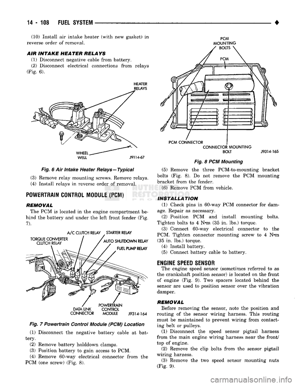
(10) Install air intake heater (with new gasket) in
reverse order of removal.
AIR
INTAKE
HE
A TER
RELA YS
(1) Disconnect negative cable from battery.
(2) Disconnect electrical connections from relays
(Fig. 6).
HEATER
RELAYS
WHEEL..
WELL
J9114-67
Fig. 6 Air intake Heater Relays—Typical (3) Remove relay mounting screws. Remove relays.
(4) Install relays in reverse order of removal.
POWERTRAIN CONTROL MODULE
(PCI)
REMOWAL The PCM is located in the engine compartment be
hind the battery and under the left front fender (Fig.
7).
TORQUE CONVERTER
CLUTCH RELAY A/C CLUTCH RELAY STARTER RELAY
AUTO SHUTDOWN RELAY FUEL PUMP RELAY DATA LINK
CONNECTOR POWERTRAIN
CONTROL
MODULE
J9314-164
Fig. 7 Powertrain Control
Module
(PCM) Location (1) Disconnect the negative battery cable at bat
tery.
(2) Remove battery holddown clamps.
(3) Position battery to gain access to PCM,
(4) Remove 60-way electrical connector from the
PCM (one screw) (Fig. 8).
PCM
MOUNTING BOLTS
PCM CONNECTOR CONNECTOR MOUNTING
BOLT
J9314-165
Fig. 8 PCM Mounting (5) Remove the three PCM-to-mounting bracket
bolts (Fig. 8). Do not remove the PCM mounting
bracket from the fender.
(6) Remove PCM from vehicle.
INSTALLATION (1) Check pins in 60-way PCM connector for dam
age.
Repair as necessary.
(2) Position PCM and install mounting bolts.
Tighten bolts to 4 N*m (35 in. lbs.) torque.
(3) Connect 60-way electrical connector to the
PCM. Tighten connector mounting screw to 4 N#m (35 in. lbs.) torque. (4) Install battery. (5) Connect battery cable to battery.
ENGINE
SPEED SENSOR
The engine speed sensor (sometimes referred to as
the crankshaft position sensor) is located on the front of engine (Fig. 9). Two spacers located behind the
sensor are used to position sensor over the vibration
damper.
REMOWAL Before removing the sensor, note the position and
routing of the sensor wiring harness. This routing must be maintained to prevent wiring from contact
ing belt or pulleys.
(1) Disconnect the speed sensor pigtail harness
from the main engine wiring harness near the front/
top of engine.
(2) Remove the clip bolts from the sensor pigtail
wiring harness. (3) Remove the two speed sensor mounting nuts
(Fig. 9).
Page 1004 of 1502
•
NV4500 MANUAL
TRANSMISSION
21 - 3
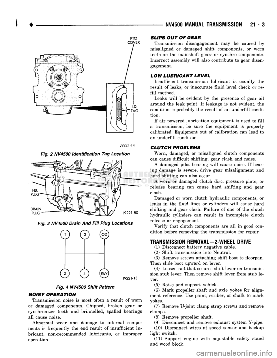
PTO
COVER
J9221-14
Fig. 2 NV4500 identification Tag Location
DRAIN
PLUG
J9221-80
Fig. 3 NV4500 Drain And Fill Plug Locations
o
0 ©
0 0©
J9221-13
Fig. 4 NV4500 Shitt Pattern
NOISY OPERATION Transmission noise is most often a result of worn
or damaged components. Chipped, broken gear or
synchronizer teeth and brinnelled, spalled bearings
all cause noise.
Abnormal wear and damage to internal compo
nents is frequently the end result of insufficient lu
bricant, non-recommended lubricants, or improper operation.
SLIPS
OUT OF
GEAR
Transmission disengagement may be caused by
misaligned or damaged shift components, or worn
teeth on the mainshaft gears or synchro components. Incorrect assembly will also contribute to gear disengagement.
LOW LUBRICANT LEWEL
Insufficient transmission lubricant is usually the
result of leaks, or inaccurate fluid level check or re
fill method.
Leaks will be evident by the presence of gear oil
around the leak point. If leakage is not evident, the
condition is probably the result of an underfill condi
tion.
If air powered lubrication equipment is used to fill
a transmission, be sure the equipment is properly
calibrated. Equipment out of calibration can lead to
an underfill condition.
CLUTCH
PROBLEMS
Worn, damaged, or misaligned clutch components
can cause difficult shifting, gear clash and noise.
A damaged pilot bearing will cause noise. If bear
ing damage is severe, drive gear misalignment and
hard shifting can also occur.
A worn or damaged clutch disc, pressure plate, or
release bearing can cause hard shifting and gear clash.
Damaged or worn clutch hydraulic components, or
leaks in the fluid lines or cylinders will cause hard shifting and gear clash. Failure of one of the clutch
hydraulic cylinders can result in incomplete clutch release or engagement.
Verify that clutch components are all in good con
dition before removing the transmission for repair.
TRANSMISSION
REMOVAL—2-WHEEL DRIVE
(1) Disconnect battery negative cable. (2) Shift transmission into Neutral.
(3) Remove screws attaching shift boot to floorpan.
Then slide boot upward on lever. (4) Loosen nut that secures shift lever on transmis
sion stub lever. Then remove shift lever from stub le
ver. (5) Raise and support vehicle.
(6) Mark propeller shaft and axle yokes for align
ment reference. Use paint, scriber, or chalk to mark
yokes.
(7) Remove U-joint clamp strap screws and remove
clamps. (8) Remove propeller shaft.
(9) Disconnect and remove exhaust system Y-pipe.
(10) Disconnect wires at speed sensor and backup
light switch. (11) Support engine with adjustable safety stand
and wood block.