heating DODGE TRUCK 1993 Service Owner's Guide
[x] Cancel search | Manufacturer: DODGE, Model Year: 1993, Model line: TRUCK, Model: DODGE TRUCK 1993Pages: 1502, PDF Size: 80.97 MB
Page 739 of 1502
9
- 134 5.9L
(DIESEL) ENGINE
• (4) Fill the engine with oil. Run the engine and
check for leaks.
(5) Stop the engine and check the oil level with the
dipstick.
CUP
PLUG
J9109-30
Fig.
17 Cup Plug Locations in Cylinder Block INSTALLATION
(1) Install the cylinder head onto the block.
(2) Install the engine assembly into the vehicle.
PISTON
/
CONNECTING ROD ASSEMBLY
The turbocharged intercooler piston has a Ni-Resist
insert with a keystone profile for the top compression
ring. The new piston has a new design bowl and a 7 mm longer piston pin. These pistons can not be in
terchanged with earlier models.
REMOVAL (1) Remove the engine assembly from the vehicle.
(2) Remove the cylinder head from the block.
(3) Remove the oil pan and suction pump.
(4) If the cylinder bores have ridges, use a ridge
reamer to cut the ridge from the top of the cylinder
bore before removing the piston. Make sure the ridge reamer does not make a deep cut into the bore. DO
NOT remove more metal than is necessary to remove
the ridge.
(5) If cylinders have ridges, the cylinders are over
size and will need boring. (6) Use a hammer and a steel stamp to mark the
cylinder number onto each connecting rod cap. Mark
the cylinder number onto the top of each piston. (7) Remove the connecting rod bolts and rod caps.
Use care so the cylinder bores and connecting rods
are not damaged. (8) Use a hammer handle or similar object to push
the piston and connecting rod through the cylinder
bore.
(9) Store the piston/rod assemblies in a rack.
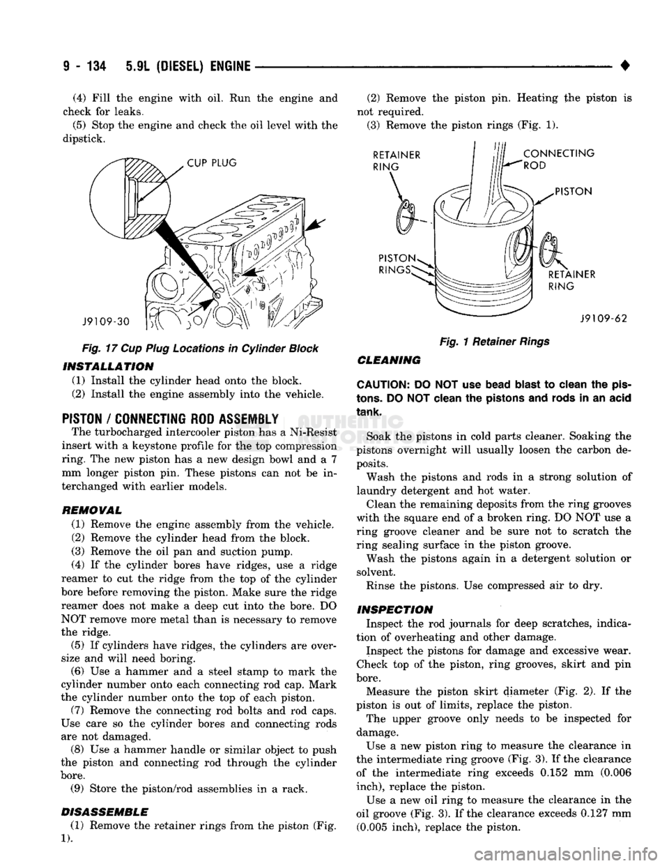
DISASSEMBLE (1) Remove the retainer rings from the piston (Fig.
1).
(2) Remove the piston pin. Heating the piston is
not required. (3) Remove the piston rings (Fig. 1). RETAINER
RING
CONNECTING
ROD
PISTON
PISTON RIN RETAINER
RING J9109-62
Fig.
1 Retainer
Rings
CLEANING
CAUTION: DO NOT use bead
blast
to clean the
pis
tons.
DO
NOT
clean the pistons and rods in an acid
tank.
Soak the pistons in cold parts cleaner. Soaking the
pistons overnight will usually loosen the carbon de posits.
Wash the pistons and rods in a strong solution of
laundry detergent and hot water.
Clean the remaining deposits from the ring grooves
with the square end of a broken ring. DO NOT use a
ring groove cleaner and be sure not to scratch the
ring sealing surface in the piston groove.
Wash the pistons again in a detergent solution or
solvent.
Rinse the pistons. Use compressed air to dry.
INSPECTION Inspect the rod journals for deep scratches, indica
tion of overheating and other damage.
Inspect the pistons for damage and excessive wear.
Check top of the piston, ring grooves, skirt and pin
bore.
Measure the piston skirt diameter (Fig. 2). If the
piston is out of limits, replace the piston.
The upper groove only needs to be inspected for
damage.
Use a new piston ring to measure the clearance in
the intermediate ring groove (Fig. 3). If the clearance of the intermediate ring exceeds 0.152 mm (0.006
inch),
replace the piston.
Use a new oil ring to measure the clearance in the
oil groove (Fig. 3). If the clearance exceeds 0.127 mm (0.005 inch), replace the piston.
Page 744 of 1502
•
5.9L
(DIESEL) ENGINE 9 - 139
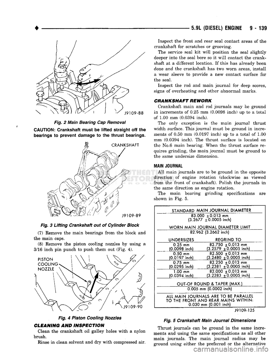
Fig.
2 Main Beating Cap
Removal
CAUTION:
Crankshaft must be
lifted
straight
off the
bearings
to
prevent
damage
to the
thrust
bearings.
Fig.
3 Lifting Crankshaft out of Cylinder
Block
(7)
Remove the main bearings from the block and
the main caps. (8) Remove the piston cooling nozzles by using a
3/16 inch pin punch to push them out (Fig. 4).
Fig.
4
Piston
Cooling
Nozzles
CLEANING
AND
INSPECTION
Clean the crankshaft oil galley holes with a nylon
brush. Rinse in clean solvent and dry with compressed air. Inspect the front and rear seal contact areas of the
crankshaft for scratches or grooving. The service seal kit will position the seal slightly
deeper into the seal bore so it will contact the crank
shaft at a different location. If this has already been
done and the crankshaft has two worn areas, install
a wear sleeve to provide a new contact surface for
the seal.
Inspect the rod and main journal for deep scores,
signs of overheating and other abnormal marks.
CRANKSHAFT
REWORK
Crankshaft main and rod journals may be ground
in increments of 0.25 mm (0.0098 inch) up to a total
of 1.00 mm (0.0394 inch). The only exception is the main journal thrust
width surface. This journal must be ground in incre ments of 0.50 mm (0.0197 inch) up to a total of 1.00
mm (0.0394 inch). The thrust surface is located on
the No.6 main bearing. When the thrust surface re quires grinding, the main journal must be ground to
the same undersize dimension.
MAIN
JOURNAL
All main journals are to be ground in the opposite
direction of engine rotation (clockwise as viewed
from the front of crankshaft). Polish the journals in
the same direction as engine rotation.
The main bearing grinding specifications are
shown in Fig. 5.
STANDARD
MAIN
JOURNAL
DIAMETER
83.000 +0.013 mm
(3.2677 ±0.0005 inch)
WORN
MAIN
JOURNAL
DIAMETER
LIMIT
82.962 (3.2662
inch)
UNDERSIZES
REGRIND
TO
0.25 mm
(0.0098
inch)
82.750 ±0.013 mm
(3.2579 ±0.0005
inch)
0.50 mm
(0.0197
inch)
82.500 +0.013 mm
(3.2480 +0.0005
inch)
0.75 mm
(0.0295
inch)
82.250 +0.013 mm
(3.2381 ±0.0005
inch)
1.00 mm
(0.0394 inch) 82.000 +0.013 mm
(3.2283 ±0.0005 inch)
OUT-OF
ROUND
&
TAPER
(MAX.)
0.005 mm (0.0002 inch)
ALL
MAIN
JOURNALS
ARE
TO
BE
PARALLEL
TO
THE
FRONT
AND
REAR
MAINS
WITHIN:
0.030
mm
(0.001 inch)
J9109-125
Fig.
5 Crankshaft Main
Journal
Dimensions
Thrust journals can be ground in the same incre
ments and using the same specifications as all other main journals. The main journal radius may be ground using either the preferred or the alternative
Page 760 of 1502
•
EXHAUST SYSTEM
AND
INTAKE MANIFOLD
11-1
CONTENTS
page
EXHAUST SYSTEM DIAGNOSIS
3
GENERAL
INFORMATION
1
SERVICE
PROCEDURES (DIESEL ENGINES)
. 17
page
SERVICE
PROCEDURES (GASOLINE ENGINES)
. 4
SPECIFICATIONS
27
GENERAL INFORMATION
EXHAUST SYSTEM
The gasoline engine exhaust system consists
of en
gine exhaust manifolds, exhaust pipe(s), catalytic converter(s), extension pipe(s), exhaust heat shields,
muffler(s)
and
exhaust tailpipe
(Fig. 1).
The diesel engine exhaust system consists
of an en
gine exhaust manifold, turbocharger, exhaust pipe,
extension pipe, muffler
and
exhaust tailpipe
(Fig. 2).
The engine exhaust manifolds
on
gasoline engines
are equipped with ball flange outlets
to
assure
a
tight seal
and
strain free connections. The exhaust system must
be
properly aligned
to
prevent stress, leakage
and
body contact.
If the
sys
tem contacts
any
body panel,
it may
amplify objec
tionable noises from
the
engine
or
body. When inspecting
an
exhaust system, critically
in
spect
for
cracked
or
loose joints, stripped screw
or
bolt threads, corrosion damage
and
worn, cracked
or
broken hangers. Replace
all
components that
are
badly corroded
or
damaged.
DO NOT
attempt
to re
pair. When replacement
is
required,
use
original equip
ment parts
(or
their equivalent). This will assure
proper alignment
and
provide acceptable exhaust
noise levels.
CAUTION:
Avoid
application
of
rust
prevention
compounds
or
undercoating materials
to
exhaust
system
floor
pan
exhaust
heat
shields.
Light
overs-
pray
near
the
edges
is
permitted. Application
of
coating
will
result
in
excessive
floor
pan
tempera
tures
and
objectionable
fumes.
CATALYTIC CONVERTER (GASOLINE ENGINES)
The stainless steel catalytic converter body
is de
signed
to
last
the
life
of the
vehicle. Excessive heat
can result
in
bulging
or
other distortion,
but
exces sive heat will
not be the
fault
of the
converter.
If un-
burned fuel enters
the
converter, overheating
may
occur.
If a
converter
is
heat-damaged, correct
the
cause
of the
damage
at the
same time
the
converter is replaced. Also, inspect
all
other components
of the
exhaust system
for
heat damage.
Unleaded gasoline must
be
used
to
avoid contami
nating
the
catalyst core.
EXHAUST HEAT SHIELDS (GASOLINE ENGINES)
Exhaust heat shields
are
needed
to
protect both
the
vehicle
and the
environment from
the
high tempera
tures developed
by the
catalytic converter.
The
com
bustion reaction facilitated
by the
catalyst releases additional heat
in the
exhaust system. Under severe
operating conditions,
the
temperature increases
in
the area
of the
reactor. Such conditions
can
exist
when
the
engine misfires
or
otherwise does
not
oper ate
at
peak efficiency.
DO NOT
remove spark plug
wires from plugs
or by any
other means short
out
cylinders. Failure
of the
catalytic converter
can
occur
due
to a
temperature increase caused
by
unburned
fuel passing through
the
converter. Do
not
allow
the
engine
to
operate
at
fast idle
for
extended periods (over
5
minutes). This condition
may result
in
excessive temperatures
in the
exhaust system
and on the
floor
pan.
EXHAUST GAS RECIRCULATION
(EGR)—(GASOLINE ENGINES)
To assist
in the
control
of
oxides
of
nitrogen
(NOx)
in engine exhaust,
all
engines
are
equipped with
an
exhaust
gas
recirculation system.
The use of
exhaust
gas
to
dilute incoming air/fuel mixtures lowers peak
flame temperatures during combustion, thus limiting
the formation
of NOx.
Exhaust gases
are
taken from openings
in the ex
haust
gas
crossover passage
in the
intake manifold. Refer
to
Group
25,
Emission Control Systems
for
complete description, diagnosis
and
service proce
dures
of the
exhaust
gas
recirculation system
and
components.
TURBOCHARGER
(5.9L
DIESEL ENGINE)
A turbocharger
is
used
to
force more
air
into
the
engine cylinders. Exhaust
gas
energy
is
used
to
turn
EXHAUST SYSTEM
AND
INTAKE MANIFOLD
Page 784 of 1502
•
EXHAUST
SYSTEM
AND
INTAKE MANIFOLD
11 - 25
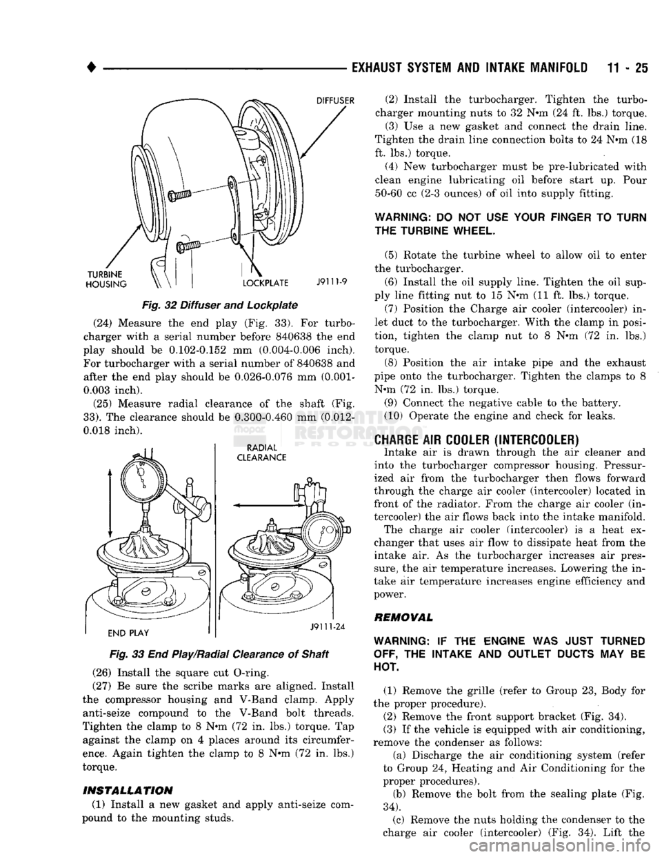
Fig.
32 Diffuser and Lockpiate (24) Measure the end play (Fig. 33). For turbo
charger with a serial number before 840638 the end
play should be 0.102-0.152 mm (0.004-0.006 inch).
For turbocharger with a serial number of 840638 and after the end play should be 0.026-0.076 mm
(0.001-
0.003 inch).
(25) Measure radial clearance of the shaft (Fig.
33).
The clearance should be 0.300-0.460 mm (0.012-
0.018 inch).
Fig.
33 End Play/Radial Clearance of Shaft
(26) Install the square cut O-ring.
(27) Be sure the scribe marks are aligned. Install
the compressor housing and V-Band clamp. Apply anti-seize compound to the V-Band bolt threads.
Tighten the clamp to 8 N-m (72 in. lbs.) torque. Tap against the clamp on 4 places around its circumfer
ence.
Again tighten the clamp to 8 N-m (72 in. lbs.)
torque.
INSTALLATION
(1) Install a new gasket and apply anti-seize com
pound to the mounting studs. (2) Install the turbocharger. Tighten the turbo
charger mounting nuts to 32 N-m (24 ft. lbs.) torque. (3) Use a new gasket and connect the drain line.
Tighten the drain line connection bolts to 24 N-m (18
ft. lbs.) torque.
(4) New turbocharger must be pre-lubricated with
clean engine lubricating oil before start up. Pour 50-60 cc (2-3 ounces) of oil into supply fitting.
WARNING:
DO NOT USE
YOUR FINGER
TO
TURN
THE TURBINE WHEEL.
(5) Rotate the turbine wheel to allow oil to enter
the turbocharger.
(6) Install the oil supply line. Tighten the oil sup
ply line fitting nut to 15 N-m (11 ft. lbs.) torque. (7) Position the Charge air cooler (intercooler) in
let duct to the turbocharger. With the clamp in posi
tion, tighten the clamp nut to 8 N-m (72 in. lbs.) torque.
(8) Position the air intake pipe and the exhaust
pipe onto the turbocharger. Tighten the clamps to 8 N-m (72 in. lbs.) torque.
(9) Connect the negative cable to the battery.
(10) Operate the engine and check for leaks.
CHARGE
AIR
COOLER (INTERCOOLER)
Intake air is drawn through the air cleaner and
into the turbocharger compressor housing. Pressur
ized air from the turbocharger then flows forward
through the charge air cooler (intercooler) located in front of the radiator. From the charge air cooler (in
tercooler) the air flows back into the intake manifold. The charge air cooler (intercooler) is a heat ex
changer that uses air flow to dissipate heat from the
intake air. As the turbocharger increases air pres
sure,
the air temperature increases. Lowering the in
take air temperature increases engine efficiency and
power.
REMOVAL
WARNING:
IF THE
ENGINE
WAS
JUST TURNED OFF,
THE
INTAKE
AND
OUTLET
DUCTS
MAY BE
HOT.
(1) Remove the grille (refer to Group 23, Body for
the proper procedure).
(2) Remove the front support bracket (Fig. 34).
(3) If the vehicle is equipped with air conditioning,
remove the condenser as follows:
(a) Discharge the air conditioning system (refer
to Group 24, Heating and Air Conditioning for the
proper procedures).
(b) Remove the bolt from the sealing plate (Fig.
34).
(c) Remove the nuts holding the condenser to the
charge air cooler (intercooler) (Fig. 34). Lift the
Page 785 of 1502
11 - 26
EXHAUST SYSTEM
AND
INTAKE MANIFOLD
• condenser and sealing plate assembly away from
the charge air cooler (intercooler).
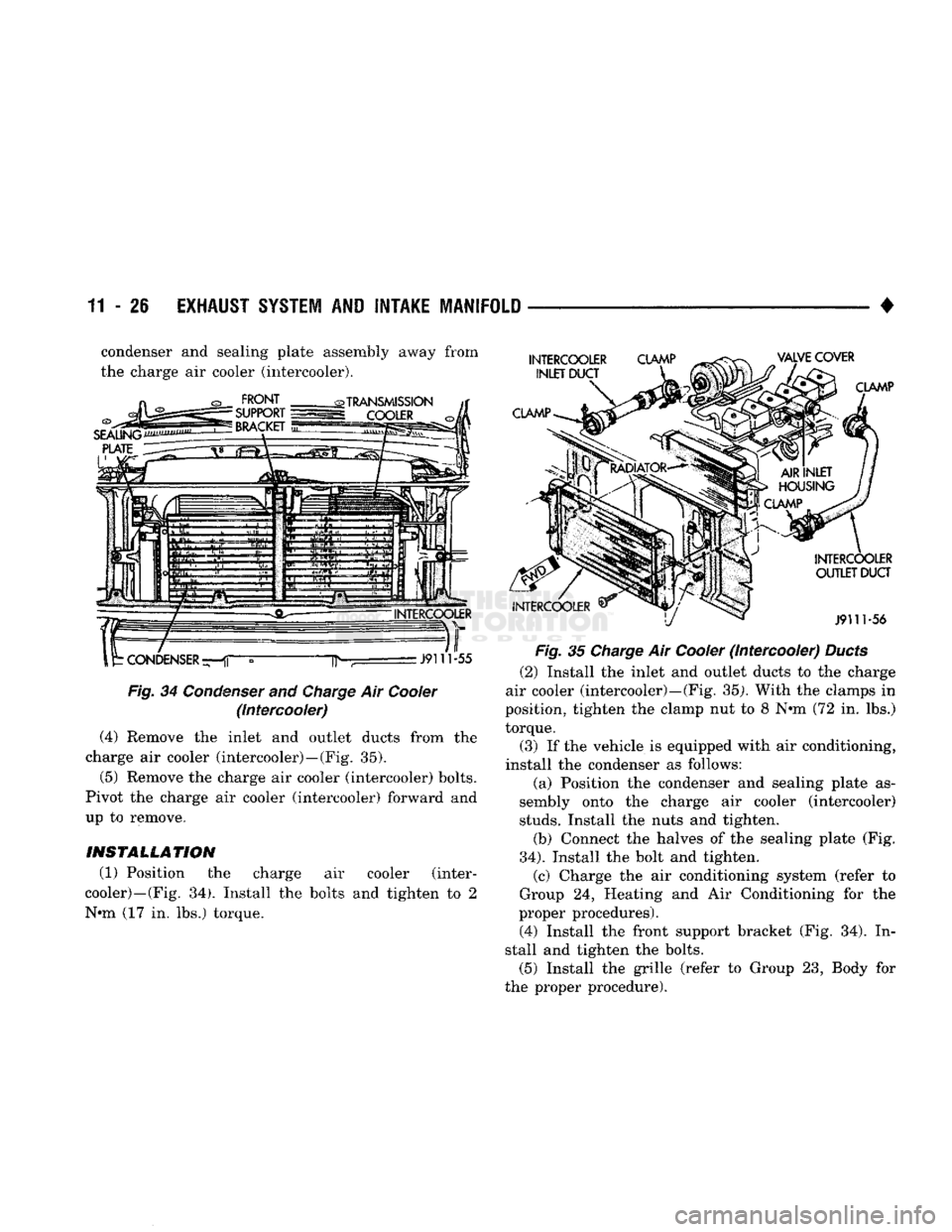
Fig.
34 Condenser and
Charge
Air Cooler (Intercooler)
(4) Remove the inlet and outlet ducts from the
charge air cooler (intercooler)—(Fig. 35).
(5) Remove the charge air cooler (intercooler) bolts.
Pivot the charge air cooler (intercooler) forward and
up to remove.
INSTALLATION
(1) Position the charge air cooler (inter
cooler)—(Fig. 34). Install the bolts and tighten to 2
N-m (17 in. lbs.) torque.
Fig.
35 Charge Air Cooler (Intercooler) Ducts
(2) Install the inlet and outlet ducts to the charge
air cooler (intercooler)—(Fig. 35). With the clamps in
position, tighten the clamp nut to 8 N-m (72 in. lbs.)
torque.
(3) If the vehicle is equipped with air conditioning,
install the condenser as follows: (a) Position the condenser and sealing plate as
sembly onto the charge air cooler (intercooler)
studs.
Install the nuts and tighten.
(b) Connect the halves of the sealing plate (Fig.
34).
Install the bolt and tighten. (c) Charge the air conditioning system (refer to
Group 24, Heating and Air Conditioning for the
proper procedures).
(4) Install the front support bracket (Fig. 34). In
stall and tighten the bolts. (5) Install the grille (refer to Group 23, Body for
the proper procedure).
Page 852 of 1502
•
FUEL SYSTEM
14 - 33 Refer to Group 8D, Ignition System for more crank
shaft position sensor information. The engine will not operate if the PCM does not re
ceive a crankshaft position sensor input.
ENGINE
COOLANT TEMPERATURE SENSOR-PCM
INPUT
The engine coolant temperature sensor is installed
next to the thermostat housing (Fig. 6) and protrudes
into the water jacket. The sensor provides an input
voltage to the powertrain control module (PCM) re
lating coolant temperature. The PCM uses this input
along with inputs from other sensors to determine in
jector pulse width and ignition timing. As coolant temperature varies, the coolant temperature sensor
resistance will change. This change in resistance results in a different input voltage to the PCM. When the engine is cold, the PCM will operate in
Open Loop cycle. It will demand slightly richer air-
fuel mixtures and higher idle speeds. This is done until normal operating temperatures are reached.
Fig.
6 Coolant
Temperature
Sensor—
Typical
IGNITION CIRCUIT
SENSE-PCM
INPUT
The ignition circuit sense input tells the power-
train control module (PCM) the ignition switch has
energized the ignition circuit. Refer to the wiring di
agrams for circuit information.
MANIFOLD ABSOLUTE
PRESSURE
(MAP)
SENSOR-PCM
INPUT
The MAP sensor reacts to absolute pressure in the
intake manifold. It provides an input voltage to the
powertrain control module (PCM). As engine load changes, manifold pressure varies. The change in
manifold pressure causes MAP sensor voltage to
change. The change in MAP sensor voltage results in a different input voltage to the PCM. The input volt
age level supplies the PCM with information about
ambient barometric pressure during engine start-up (cranking) and engine load while the engine is run ning. The PCM uses this input along with inputs
from other sensors to adjust air-fuel mixture.
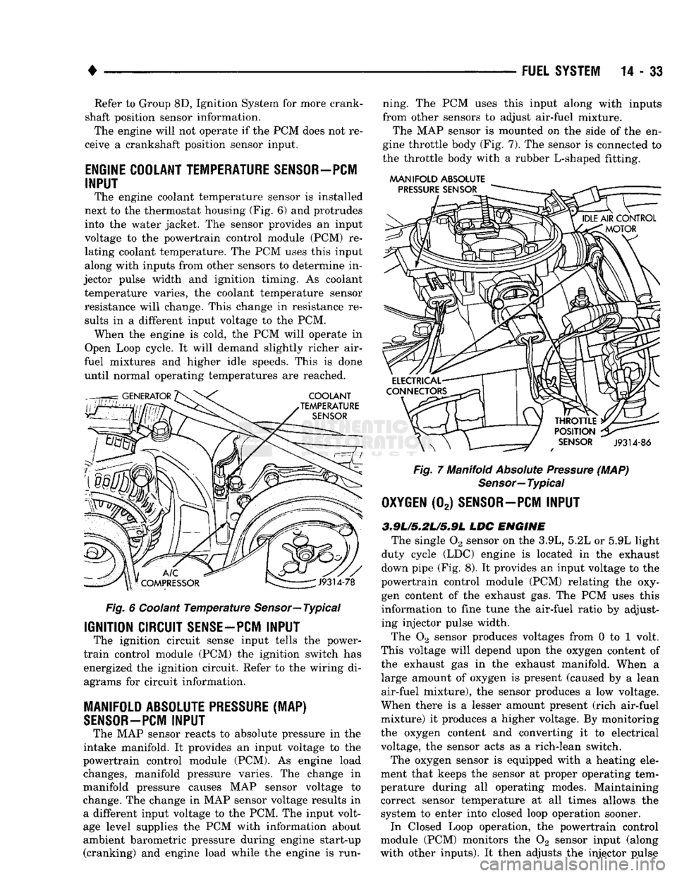
The MAP sensor is mounted on the side of the en
gine throttle body (Fig. 7). The sensor is connected to
the throttle body with a rubber L-shaped fitting.
MANIFOLD
ABSOLUTE
Fig.
7 Manifold
Absolute
Pressure
(MAP)
Sensor—
Typical
OXYGEN
(02)
SENSOR—PCM
INPUT
3.9L/5.2L/S»9L
LDC
ENGINE
The single 02 sensor on the 3.9L, 5.2L or 5.9L light
duty cycle (LDC) engine is located in the exhaust
down pipe (Fig. 8). It provides an input voltage to the
powertrain control module (PCM) relating the oxy
gen content of the exhaust gas. The PCM uses this
information to fine tune the air-fuel ratio by adjust ing injector pulse width.
The 02 sensor produces voltages from 0 to 1 volt.
This voltage will depend upon the oxygen content of
the exhaust gas in the exhaust manifold. When a large amount of oxygen is present (caused by a lean
air-fuel mixture), the sensor produces a low voltage.
When there is a lesser amount present (rich air-fuel
mixture) it produces a higher voltage. By monitoring
the oxygen content and converting it to electrical
voltage, the sensor acts as a rich-lean switch.
The oxygen sensor is equipped with a heating ele
ment that keeps the sensor at proper operating tem
perature during all operating modes. Maintaining
correct sensor temperature at all times allows the system to enter into closed loop operation sooner. In Closed Loop operation, the powertrain control
module (PCM) monitors the 02 sensor input (along
with other inputs). It then adjusts the injector pulse
Page 855 of 1502
trol (IAC) stepper motor position to compensate for
increased engine load from the A/C compressor.
By switching the ground path for the relay on and
off, the PCM is able to cycle the A/C compressor
clutch. This is based on changes in engine operating
conditions. If, during A/C operation, the PCM senses
low idle speeds or a wide open throttle condition, it
will de-energize the relay. This prevents A/C clutch engagement. The relay will remain de-energized un
til the idle speed increases or the wide open throttle condition exceeds 15 seconds or no longer exists. The
PCM will also de-energize the relay if coolant tem
perature exceeds 125°C (257°F).
IDLE
AIR
CONTROL
(IAC)
MOTOR-PCM OUTPUT
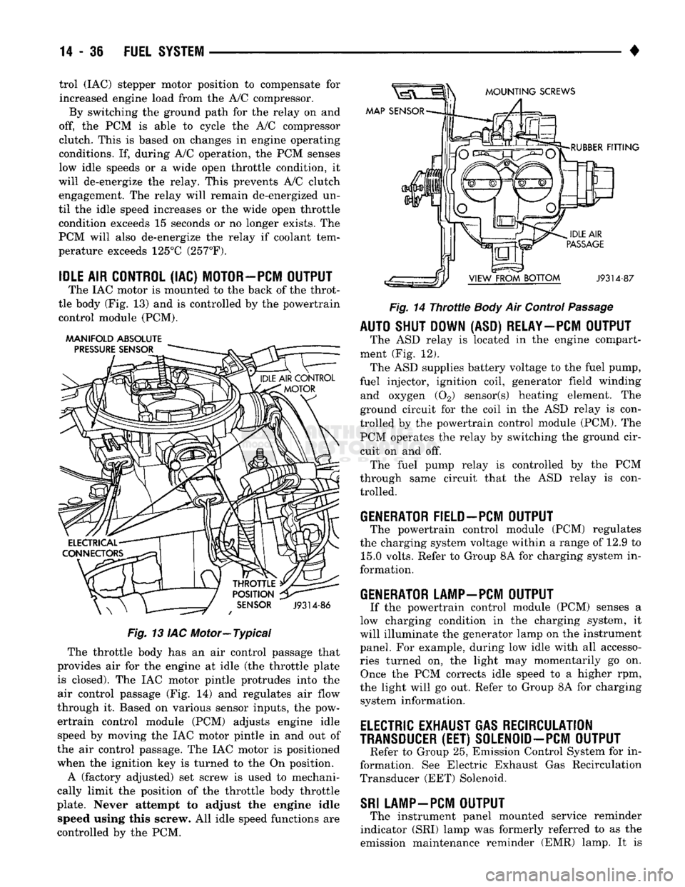
The IAC motor is mounted to the back of the throt
tle body (Fig. 13) and is controlled by the powertrain control module (PCM).
AAANIFOLD ABSOLUTE
PRESSURE
SENSOR
MOUNTING
SCREWS
MAP SENSOR
THROTTLE
POSITION
SENSOR
J9314-86
Fig.
13 IAC Motor—Typical The throttle body has an air control passage that
provides air for the engine at idle (the throttle plate is closed). The IAC motor pintle protrudes into the
air control passage (Fig. 14) and regulates air flow
through it. Based on various sensor inputs, the pow
ertrain control module (PCM) adjusts engine idle speed by moving the IAC motor pintle in and out of
the air control passage. The IAC motor is positioned
when the ignition key is turned to the On position.
A (factory adjusted) set screw is used to mechani
cally limit the position of the throttle body throttle
plate. Never attempt to adjust the engine idle speed using this screw. All idle speed functions are
controlled by the PCM.
RUBBER
FITTING
J9314-87
Fig.
14
Throttle
Body
Air Control
Passage
AUTO SHUT DOWN (ASD) RELAY—PCM OUTPUT
The ASD relay is located in the engine compart
ment (Fig. 12). The ASD supplies battery voltage to the fuel pump,
fuel injector, ignition coil, generator field winding and oxygen (02) sensor(s) heating element. The
ground circuit for the coil in the ASD relay is con
trolled by the powertrain control module (PCM). The PCM operates the relay by switching the ground cir
cuit on and off. The fuel pump relay is controlled by the PCM
through same circuit that the ASD relay is con trolled.
GENERATOR FIELD-PCM OUTPUT
The powertrain control module (PCM) regulates
the charging system voltage within a range of 12.9 to 15.0 volts. Refer to Group 8A for charging system in
formation.
GENERATOR LAMP-PCM OUTPUT
If the powertrain control module (PCM) senses a
low charging condition in the charging system, it
will illuminate the generator lamp on the instrument
panel. For example, during low idle with all accesso
ries turned on, the light may momentarily go on. Once the PCM corrects idle speed to a higher rpm,
the light will go out. Refer to Group 8A for charging system information.
ELECTRIC
EXHAUST GAS RECIRCULATION
TRANSDUCER
(EET)
S0LEN0ID-PCM OUTPUT
Refer to Group 25, Emission Control System for in
formation. See Electric Exhaust Gas Recirculation
Transducer (EET) Solenoid.
SRI
LAMP-PCM OUTPUT
The instrument panel mounted service reminder
indicator (SRI) lamp was formerly referred to as the
emission maintenance reminder (EMR) lamp. It is
Page 862 of 1502
MULTI-PORT
FUEL
INJECTION
(MPI)—GENERAL DIAGNOSIS—EXCEPT DIESEL
INDEX
page
Camshaft Position Sensor Testing
............
52
Charge
Air
Temperature Sensor Test
52
Coolant Temperature Sensor Test
52
Crankshaft Position Sensor Test
54
Diagnostic Trouble Code (DTC)
60
DRB
II
Scan
Tool
........................
60
Fuel
Injector
Test
57
Fuel Pump Pressure Test
57
Idle
Air
Control
(IAC) Motor Test
55
Manifold Absolute Pressure (MAP) Sensor Test
. 53
page
On-Board
Diagnostics (OBD)
59
Oxygen
(02)
Sensor Heating Element Test
54
Powertrain
Control
Module (PCM) 60-Way Connector
. 47
Relays—Operation/Testing
56
Starter
Motor Relay Test
57
System
Schematics
. 47
Throttle
Position Sensor (TPS) Test
54
Visual Inspection
43
VISUAL
INSPECTION
A visual inspection
for
loose, disconnected,
or
incor
rectly routed wires
and
hoses should
be
made. This should
be
done before attempting
to
diagnose
or
ser
vice
the
fuel injection system.
A
visual check will
help spot these faults
and
save unnecessary test
and
diagnostic time.
A
thorough visual inspection will
in
clude
the
following checks: (1) Verify that
the
60-way connector
is
fully
in
serted into
the
connector
of the
powertrain control
module
(PCM) (Fig. 1).
Verify that
the
connector
mounting screw
is
tightened
to 4 N#m (35 in. lbs.)
torque.
PCM
MOUNTING
BOLTS
PCM CONNECTOR CONNECTOR MOUNTING BOLT
J9314-165
Fig.
1
Powertrain Control
Module
(PCM) (2) Inspect
the
battery cable connections.
Be
sure
that they
are
clean
and
tight.
(3) Inspect fuel pump relay
and air
conditioning
compressor clutch relay
(if
equipped). Inspect
the
ASD relay connections. Inspect starter motor relay connections. Inspect relays
for
signs
of
physical dam
age
and
corrosion.
The
relays
are
located
in the en
gine compartment
(Fig. 2).
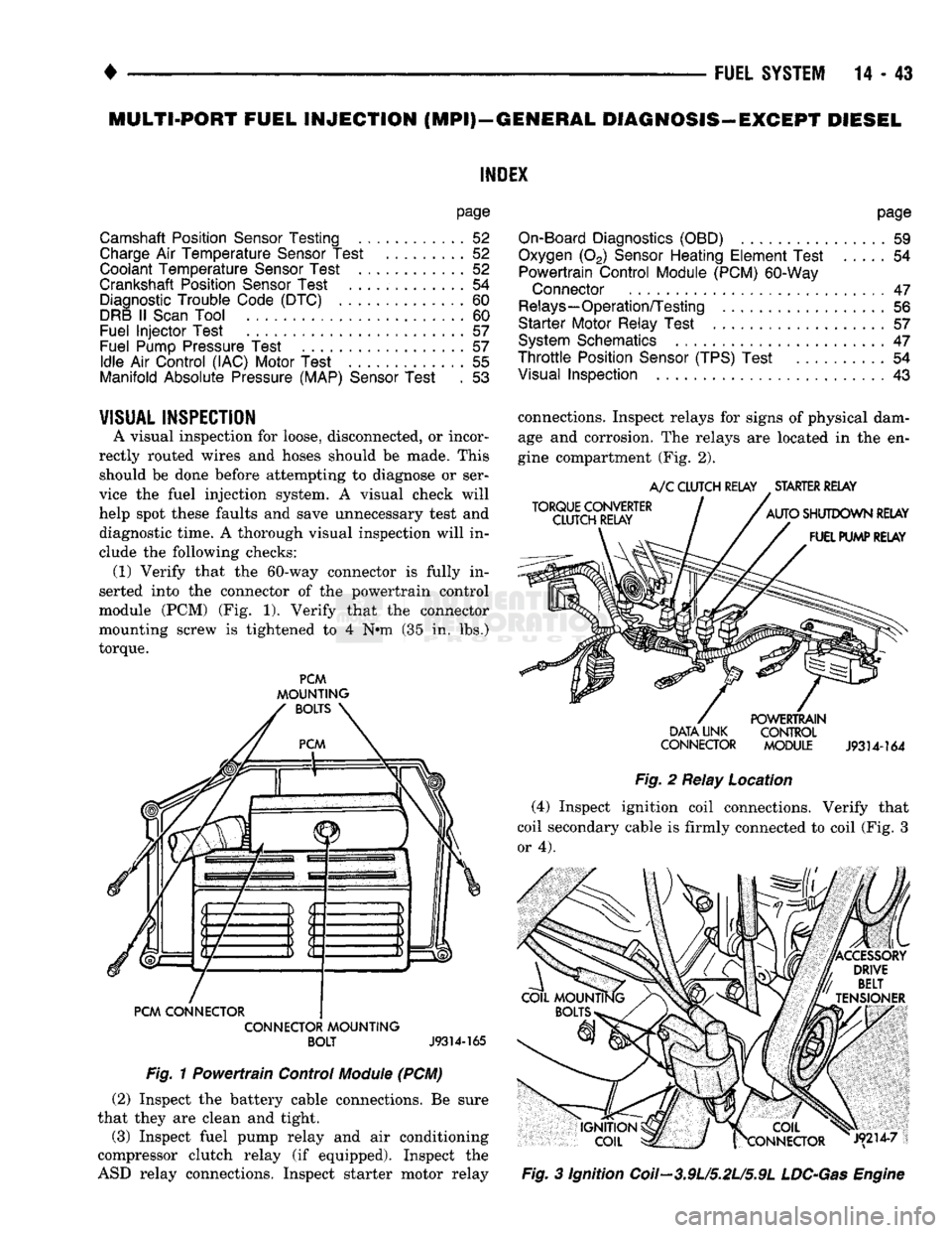
TORQUE CONVERTER
CLUTCH RELAY
A/C
CLUTCH RELAY STARTER RELAY
AUTO SHUTDOWN RELAY FUEL PUMP RELAY POWERTRAIN
DATA UNK CONTROL
CONNECTOR MODULE
J9314-164
Fig.
2
Relay Location (4) Inspect ignition coil connections. Verify that
coil secondary cable
is
firmly connected
to
coil (Fig.
3
or 4).
|X COIL
frCONNECTOR J9214-7
Fig.
3
Ignition Coil—3.9U5.2L/5.9L
LDC-Gas
Engine
Page 873 of 1502
14-54 FUEL SYSTEM
• is good, replace the PCM. If terminal/pin-4 has a
short circuit to 12 volts +, correct this condition be
fore replacing the PCM.
CRANKSHAFT POSITION SENSOR TEST
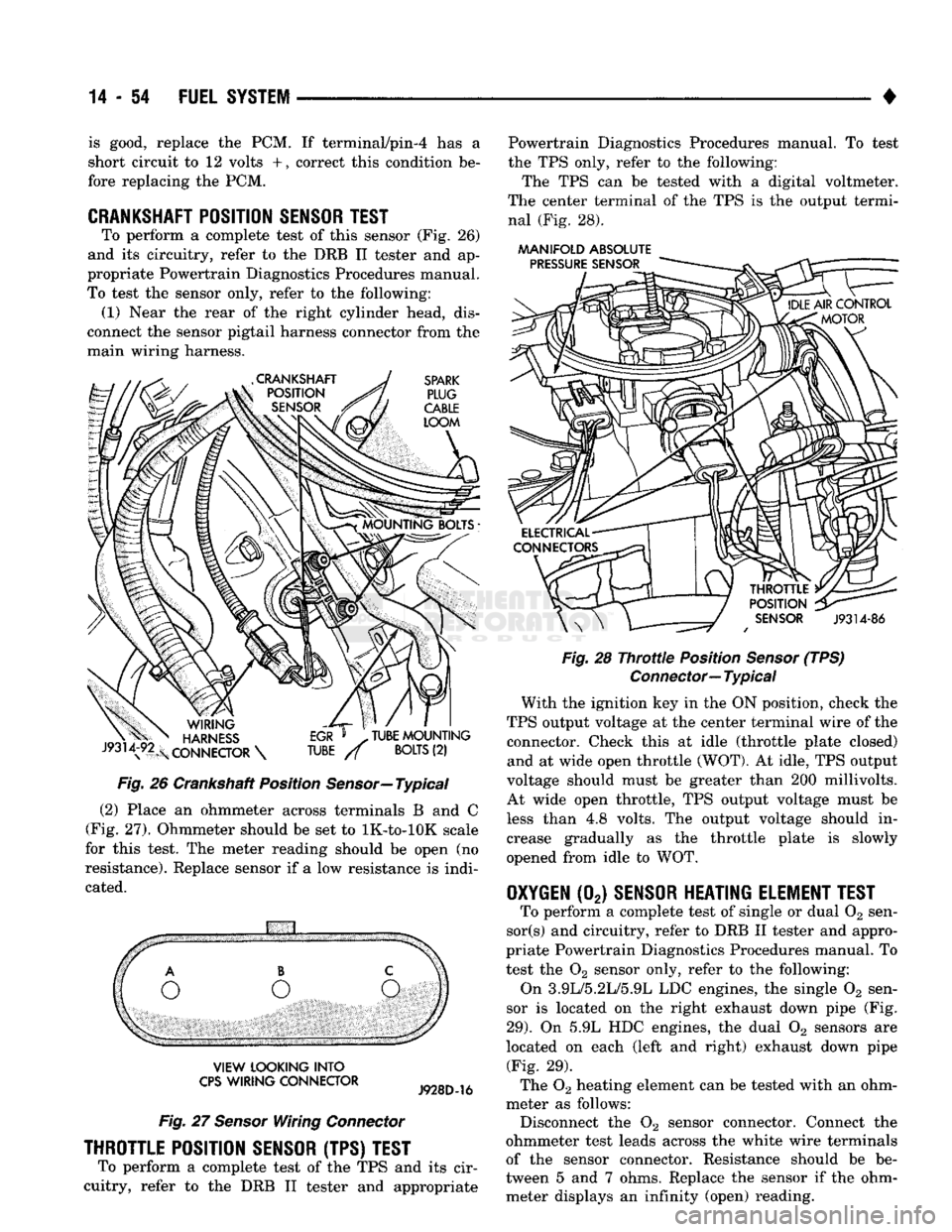
To perform a complete test of this sensor (Fig. 26)
and its circuitry, refer to the DRB II tester and ap
propriate Powertrain Diagnostics Procedures manual.
To test the sensor only, refer to the following: (1) Near the rear of the right cylinder head, dis
connect the sensor pigtail harness connector from the
main wiring harness.
Fig.
26 Crankshaft Position
Sensor—
Typical
(2) Place an ohmmeter across terminals B and C
(Fig. 27). Ohmmeter should be set to lK-to-lOK scale
for this test. The meter reading should be open (no
resistance). Replace sensor if a low resistance is indi
cated.
VIEW
LOOKING
INTO
CPS
WIRING
CONNECTOR
Fig.
27
Sensor
Wiring
Connector
THROTTLE POSITION SENSOR (TPS) TEST
To perform a complete test of the TPS and its cir
cuitry, refer to the DRB II tester and appropriate Powertrain Diagnostics Procedures manual. To test
the TPS only, refer to the following:
The TPS can be tested with a digital voltmeter.
The center terminal of the TPS is the output termi nal (Fig. 28).
AAANIFOLD
ABSOLUTE
Fig.
28
Throttle
Position
Sensor
(TPS)
Connector—
Typical
With the ignition key in the ON position, check the
TPS output voltage at the center terminal wire of the connector. Check this at idle (throttle plate closed) and at wide open throttle (WOT). At idle, TPS output
voltage should must be greater than 200 millivolts.
At wide open throttle, TPS output voltage must be
less than 4.8 volts. The output voltage should in
crease gradually as the throttle plate is slowly
opened from idle to WOT.
OXYGEN
(02)
SENSOR HEATING ELEMENT TEST
To perform a complete test of single or dual 02 sen-
sor(s) and circuitry, refer to DRB II tester and appro
priate Powertrain Diagnostics Procedures manual. To
test the 02 sensor only, refer to the following:
On 3.9L/5.2L/5.9L LDC engines, the single 02 sen
sor is located on the right exhaust down pipe (Fig.
29).
On 5.9L HDC engines, the dual 02 sensors are
located on each (left and right) exhaust down pipe (Fig. 29).
The 02 heating element can be tested with an ohm
meter as follows: Disconnect the 02 sensor connector. Connect the
ohmmeter test leads across the white wire terminals
of the sensor connector. Resistance should be be
tween 5 and 7 ohms. Replace the sensor if the ohm meter displays an infinity (open) reading.
Page 911 of 1502
14-92
FUEL
SYSTEM
• A broken injection pump timing mechanism spring
will cause the timing to be fully advanced resulting
in torque loss, a fuel knock and possible engine over
heating.
An improperly operating KSB (cold start) solenoid
will cause white smoke during engine warm-up. The
KSB solenoid is not serviceable.
A defective or non-adjustable fuel injection pump
can cause starting problems or prevent the engine
from revving up. It can also cause:
• Engine surge at idle • Rough idle (warm engine)
• Engine miss under load
• Low power
• Excessive fuel consumption
• Poor performance
• Low power
• Black smoke from the exhaust • Blue or white fog like exhaust
• Incorrect idle or maximum speed A worn fuel injection pump plunger can effect fuel
pressure and the amount of fuel injected. This results in reduced engine power. In most cases, if the injec
tion pump is delivering fuel from one outlet, it will deliver fuel from all outlets. If the internal plunger is defective, the fuel injection pump must be re
placed.
Engine power is also effected by the governor set
ting and performance. Do not attempt to adjust the governor. If the governor seals on the external adjustment screw are broken, the fuel rate may
be out of adjustment. The warranty of the injec tion pump and the engine may be void if the
seals have been tampered with or removed.
FUEL
INJECTORS
A leaking fuel injector can cause fuel knock, poor
performance, black smoke, poor fuel economy and
rough engine idle. If the fuel injector needle valve
does not operate properly, the engine may misfire and produce low power. A leak in the injection pump-to-injector high pres
sure fuel line can cause many of the same symptoms as a malfunctioning injector. Inspect for a leak in the
high pressure lines before checking for a malfunc
tioning fuel injector.
WARNING:
THE
INJECTION PUMP SUPPLIES HIGH
PRESSURE
FUEL
OF
APPROXIMATELY
59,000
KPA
(8,000
PSI) TO
EACH INDIVIDUAL INJECTOR
THROUGH THE HIGH
PRESSURE
LINES. FUEL UN
DER
THIS AMOUNT
OF
PRESSURE
CAN
PENE
TRATE THE SKIN AND CAUSE PERSONAL INJURY,
WEAR
SAFETY GOGGLES
AND
ADEQUATE PRO
TECTIVE CLOTHING. AVOID CONTACT
WITH
FUEL
SPRAY
WHEN BLEEDING HIGH
PRESSURE
FUEL
LINES.
WARNING:
DO NOT
BLEED
AIR
FROM
THE
FUEL
SYSTEM
OF A
HOT ENGINE.
DO
NOT ALLOW FUEL
TO SPRAY ONTO THE EXHAUST MANIFOLD WHEN
BLEEDING
AIR
FROM THE FUEL SYSTEM.
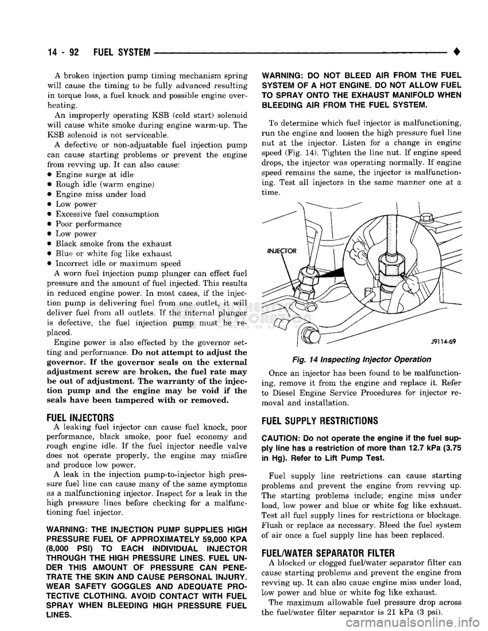
To determine which fuel injector is malfunctioning,
run the engine and loosen the high pressure fuel line nut at the injector. Listen for a change in engine
speed (Fig. 14). Tighten the line nut. If engine speed
drops,
the injector was operating normally. If engine
speed remains the same, the injector is malfunction
ing. Test all injectors in the same manner one at a
time.
Fig. 14
Inspecting
Injector Operation
Once an injector has been found to be malfunction
ing, remove it from the engine and replace it. Refer
to Diesel Engine Service Procedures for injector re moval and installation.
FUEL
SUPPLY
RESTRICTIONS
CAUTION:
Do not
operate
the
engine
if the
fuel
sup ply
line
has
a
restriction
of
more
than
12.7
kPa
(3.75
in
Hg).
Refer
to
Lift
Pump
Test.
Fuel supply line restrictions can cause starting
problems and prevent the engine from revving up.
The starting problems include; engine miss under load, low power and blue or white fog like exhaust.
Test all fuel supply lines for restrictions or blockage.
Flush or replace as necessary. Bleed the fuel system
of air once a fuel supply line has been replaced.
FUEL/WATER
SEPARATOR
FILTER
A blocked or clogged fuel/water separator filter can
cause starting problems and prevent the engine from
revving up. It can also cause engine miss under load,
low power and blue or white fog like exhaust. The maximum allowable fuel pressure drop across
the fuel/water filter separator is 21 kPa (3 psi).