weight DODGE TRUCK 1993 Service Owner's Guide
[x] Cancel search | Manufacturer: DODGE, Model Year: 1993, Model line: TRUCK, Model: DODGE TRUCK 1993Pages: 1502, PDF Size: 80.97 MB
Page 673 of 1502
9
- 68 5.2L
ENGINE
• INSTALLATION
(1) Be sure that compression ring gaps are stag
gered so that neither is in-line with oil ring rail gap.
(2) Before installing the ring compressor, make
sure the oil ring expander ends are butted and the
rail gaps located properly (Fig. 14).
(3) Immerse the piston head and rings in clean en
gine oil. Slide Piston Ring Compressor Tool C-385
over the piston and tighten with the special wrench (part of Tool C-385). Be sure position of rings does
not change during this operation.
(4) Install connecting rod bolt protectors on rod
bolts,
the long protector should be installed on the numbered side of the connecting rod. (5) Rotate crankshaft so that the connecting rod
journal is on the center of the cylinder bore. Be sure connecting rod and cylinder bore number are the same. Insert rod and piston into cylinder bore and
guide rod over the crankshaft journal.
(6) Tap the piston down in cylinder bore, using a
hammer handle. At the same time, guide connecting rod into position on crankshaft journal.
(7) The notch or groove on top of piston must be
pointing toward front of engine. The larger chamfer
of the connecting rod bore must be installed toward
crankshaft journal fillet.
(8) Install rod caps. Be sure connecting rod, con
necting rod cap and cylinder bore number are the same. Install nuts on cleaned and oiled rod bolts and
tighten nuts to 61 N®m (45 ft. lbs.) torque.
(9) Install the oil pan.
(10) Install the cylinder head.
(11) Install the engine into the vehicle.
CRANKSHAFT
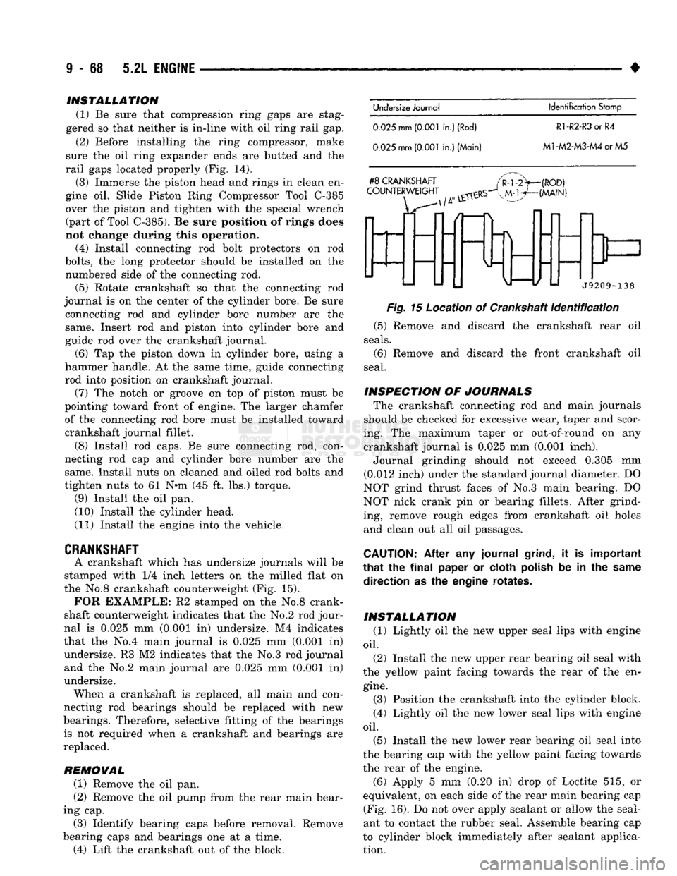
A crankshaft which has undersize journals will be
stamped with 1/4 inch letters on the milled flat on
the No.8 crankshaft counterweight (Fig. 15).
FOR
EXAMPLE: R2 stamped on the No.8 crank
shaft counterweight indicates that the No.2 rod jour
nal is 0.025 mm (0.001 in) undersize. M4 indicates
that the No.4 main journal is 0.025 mm (0.001 in) undersize. R3 M2 indicates that the No.3 rod journal and the No.2 main journal are 0.025 mm (0.Q01 in)
undersize. When a crankshaft is replaced, all main and con
necting rod bearings should be replaced with new
bearings. Therefore, selective fitting of the bearings is not required when a crankshaft and bearings are
replaced.
REMOVAL (1) Remove the oil pan.
(2) Remove the oil pump from the rear main bear
ing cap. (3) Identify bearing caps before removal. Remove
bearing caps and bearings one at a time. (4) Lift the crankshaft out of the block.
Undersize
Journal
Identification
Stamp
0.025
mm
(0.001
in.)
(Rod)
R1-R2-R3
or R4
0.025
mm
(0.001
in.) (Main)
M1-M2-M3-M4
or M5
#8
CRANKSHAFT
COUNTERWEIGHT
(ROD)
(MAIN)
f
J9209-138
Fig.
15 Location of Crankshaft
Identification
(5) Remove and discard the crankshaft rear oil
seals.
(6) Remove and discard the front crankshaft oil
seal.
INSPECTION OF JOURNALS The crankshaft connecting rod and main journals
should be checked for excessive wear, taper and scor
ing. The maximum taper or out-of-round on any crankshaft journal is 0.025 mm (0.001 inch). Journal grinding should not exceed 0.305 mm
(0.012 inch) under the standard journal diameter. DO
NOT grind thrust faces of No.3 main bearing. DO
NOT nick crank pin or bearing fillets. After grind ing, remove rough edges from crankshaft oil holes
and clean out all oil passages.
CAUTION:
After any journal
grind,
it is important
that
the
final
paper or cloth
polish
be in the
same
direction as the engine rotates.
INSTALLATION (1) Lightly oil the new upper seal lips with engine
oil.
(2) Install the new upper rear bearing oil seal with
the yellow paint facing towards the rear of the en
gine.
(3) Position the crankshaft into the cylinder block.
(4) Lightly oil the new lower seal lips with engine
oil.
(5) Install the new lower rear bearing oil seal into
the bearing cap with the yellow paint facing towards
the rear of the engine.
(6)
Apply 5 mm (0.20 in) drop of Loctite 515, or
equivalent, on each side of the rear main bearing cap (Fig. 16). Do not over apply sealant or allow the seal
ant to contact the rubber seal. Assemble bearing cap
to cylinder block immediately after sealant applica tion.
Page 678 of 1502
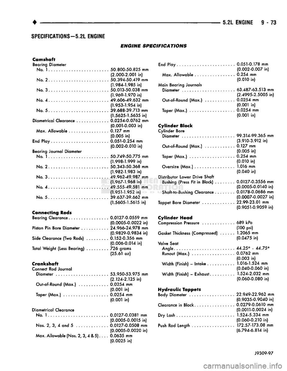
SPECIFICATIONS—5.2L
ENGINE
ENGINE SPECIFICATIONS
Camshaft
Bearing Diameter
No.
1....................... . 50.800-50.825 mm (2.000-2.001 in)
No.
2... 50.394-50.419 mm (1.984-1.985 in)
No.
3. . 50.013-50.038 mm
(1.969-1.970
in)
No.
4...........
......... 49.606-49.632 mm (1.953-1.954 in)
No.
5 39.688-39.713 mm
(1.5625-1.5635 in)
Diametrical Clearance 0.0254-0.0762 mm (0.001-0.003 in)
Max. Allowable 0.127 mm (0.005 in)
End Play. . .... 0.051-0.254 mm (0.002-0.010 in)
Bearing Journal Diameter
No.
1....................... . 50.749-50.775 mm (1.998-1.999 in)
No.
2 50.343-50.368 mm
(1.982-1.983
in)
No.
3... 49.962-49.987 mm (1.967-1.968 in)
No.
4. ......... .......... 49.555-49.581 mm (1.951-1.952 in)
No.
5 39.637-39.662 mm
(1.5605-1.5615 in)
Connecting
Rods
Bearing Clearance 0.0127-0.0559 mm (0.0005-0.0022 in)
Piston Pin Bore Diameter . 24.966-24.978 mm (0.9829-0.9834 in)
Side Clearance (Two Rods) ......... 0.152-0.356 mm (0.006-0.014 in)
Total Weight (Less Bearing) ......... 726 grams (25.61 oz)
Crankshaft
Connect Rod Journal Diameter ....... 53.950-53.975 mm (2.124-2.125 in)
Out-of-Round (Max.) ............ 0.0254 mm (0.001 in)
Taper (Max.) .... ...... 0.0254 mm (0.001 in)
Diametrical Clearance
No.
1 0.0127-0.0381 mm (0.0005-0.0015 in)
Nos.
2, 3, 4 and 5 ............. 0.0127-0.0508 mm (0.0005-0.0020 in)
Max. Allowable (Nos. 2, 3,4&5) 0.0635 mm (0.0025 in) End Play 0.051-0.178 mm
(0.002-0.007 in)
Max. Allowable 0.254 mm (0.010 in)
Main Bearing Journals Diameter ..................... 63.487-63.513 mm (2.4995-2.5005 in)
Out-of-Round (Max.) 0.0254 mm (0.001 in)
Taper (Max.) 0.0254 mm (0.001 in)
Cylinder
Block
Cylinder Bore Diameter 99.314-99.365 mm (3.910-3.912 in)
Out-of-Round (Max.) ............ 0.127 mm (0.005 in)
Taper (Max.) 0.254 mm (0.010 in)
Oversize (Max.) ................ 1.016 mm (0.040 in)
Distributor Lower Drive Shaft Bushing (Press Fit in Block) 0.0127-0.3556 mm (0.0005-0.0140 in)
Shaft-to-Bushing Clearance ........ 0.0178-0.0686 mm (0.0007-0.0027 in)
Tappet Bore Diameter ......... 22.99-23.01 mm (0.9051-0.9059 in)
Cylinder
Head
Compression Pressure 689 kPa (100 psi)
Gasket Thickness (Compressed) ......
1.2065
mm (0.0475 in)
Valve Seat Angle. .... 44.25° - 44.75° Runout (Max.) .......... ... 0.0762 mm (0.003 in)
Width (Finish) - Intake
1.016-1.524
mm
(0.040-0.060 in)
Width (Finish) - Exhaust. .........
1.524-2.032
mm (0.060-0.080 in)
Hydraulic
Tappets Body Diameter 22.949-22.962 mm (0.9035-0.9040 in)
Clearance in Block . 0.0279-0.0610 mm (0.0011-0.0024 in)
Dry
Lash
1.524-5.334
mm (0.060-0.210 in)
Push Rod Length ............. 172.57-173.08 mm (6.794-6.814 in)
J9309-97
Page 679 of 1502
ENGINE
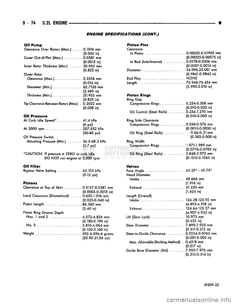
SPECIFICATIONS
(CONT*)
Oil Pump
Clearance Over Rotors (Max.)..... 0.1016 mm (0.004 in)
Cover
Out-of-Flat
(Max.).. ... 0.0381 mm (0.0015 in)
Inner
Rotor
Thickness (Min.) 20.955 mm (0.825 in)
Outer
Rotor
Clearance (Max.)............. 0.3556 mm
(0.014 in)
Diameter
(Min.) 62.7126 mm (2.469 in)
Thickness (Min.) 20.955 mm
(0.825 in)
Tip Clearance
Between
Rotors (Max). . 0.2032 mm
(0.008 in)
Oil Pressure
At Curb
Idle
Speed*
41.4 kPa
(6 psi)
At 3000 rpm 207-552 kPa (30-80 psi)
Oil Pressure
Switch
Actuating
Pressure (Min.) . 34.5-48.3 kPa (5-7 psi)
*CAUTION:
If pressure is
ZERO
at
curb
idle,
DO
NOT run
engine
at 3,000 rpm.
Oil
Filter
Bypass
Valve
Setting
............
62-103 kPa
(9-15 psi)
Pistons
Clearance at Top of
Skirt
.... 0.0127-0.0381 mm (0.0005-0.0015 in)
Land Clearance
(Diametrical)
..... 0.635-1.016 mm (0.025-0.040 in)
Piston
Length
.................
86.360 mm
(3.40 in)
Piston Ring Groove
Depth
Nos.
1 and 2 4.572-4.826 mm (0.180-0.190 in)
No.
3 3.810-4.064 mm (0.150-0.160 in)
Weight
592.6-596.6 grams
(20.90-21.04 oz) Piston Pins
Clearance In Piston . 0.00635-0.01905 mm (0.00025-0.00075 in)
In Rod
(interference)
..........
0.0178-0.0356 mm (0.0007-0.0014 in)
Diameter.
24.996-25.001 mm (0.9841-0.9843 in)
End
Play
NONE
Length
75.946-76.454 mm (2.990-3.010 in)
Piston
Rings
Ring Gap Compression
Rings
. 0.254-0.508 mm (0.010-0.020 in)
Oil
Control
(Steel
Rails) . 0.254-1.270 mm (0.010-0.050 in)
Ring Side Clearance Compression
Rings
0.038-0.076 mm (0.0015-0.0030 in)
Oil Ring
(Steel
Rails)
..........
0.06-0.21 mm (0.002-0.008 in)
Ring
Width
Compression
Rings
1.971-1.989 mm (0.0776-0.0783 in)
Oil Ring
(Steel
Rails) 3.848-3.975 mm (0.1515-0.1565 in)
V®hr©s
Face Angle 43.25° - 43.75°
Head
Diameter
Intake
.....................
48.666 mm (1.916 in)
Exhaust 41.250 mm (1.624 in)
Length
(Overall)
Intake
. 124.28-125.92 mm (4.893-4.918 in)
Exhaust . 124.64-125.27 mm (4.907-4.932 in)
Lift
(Zero
Lash) 10.973 mm (0.432 in)
Stem
Diameter
7.899-7.925 mm (0.311-0.312 in)
Stem-to-Guide
Clearance......... 0.0254-0.0762 mm (0.001-0.003 in)
Max.
Allowable
(Rocking Method). . 0.4318 mm
(0.017 in)
Guide Bore
Diameter
(Std) 7.950-7.976 mm (0.313-0.314 in)
J9309-32
Page 680 of 1502
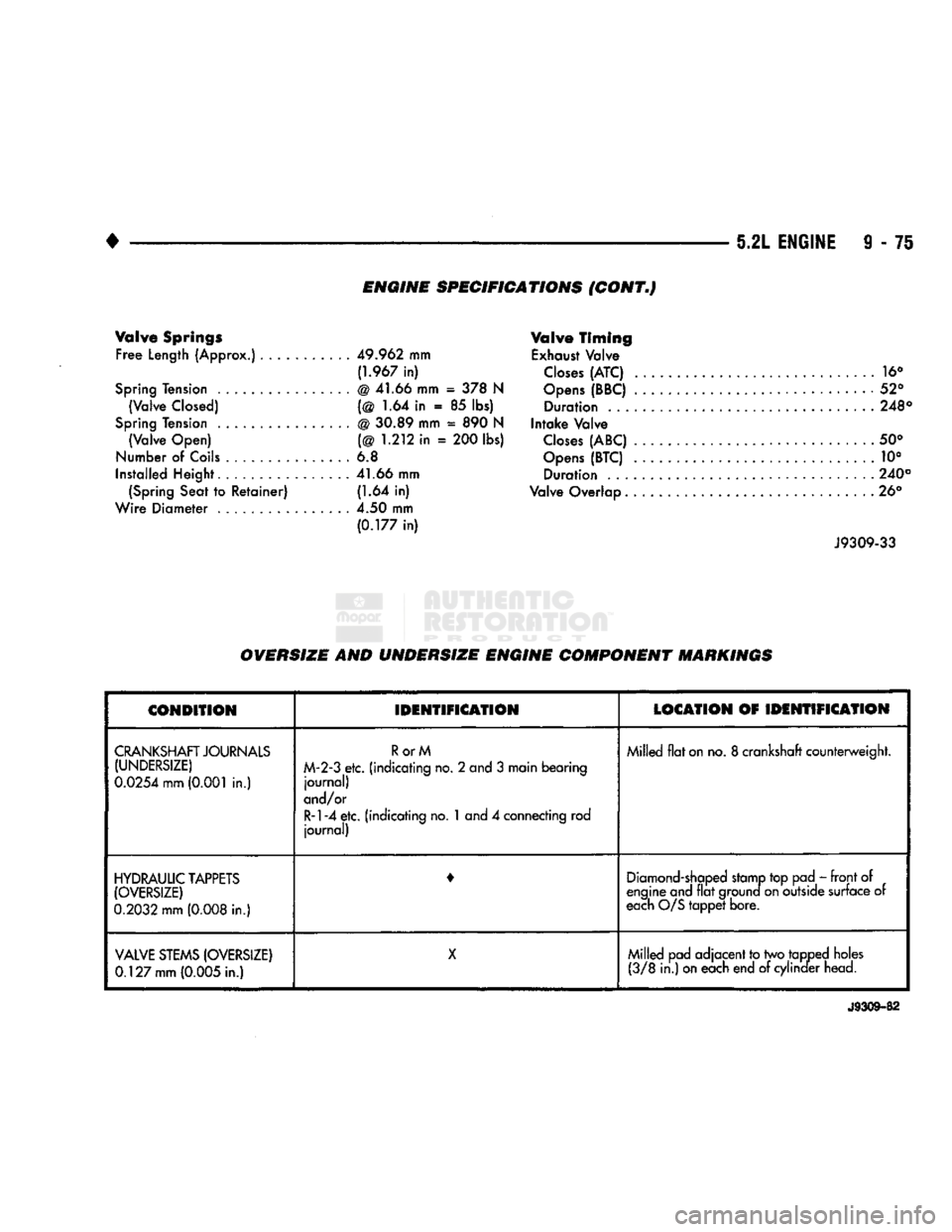
ENGINE SPECIFICATIONS (CONT,)
Valve Springs Free
Length
(Approx.)
49.962
mm
(1.967
in)
Spring Tension
.
@ 41.66 mm
= 378 N
(Valve
Closed)
(@ 1.64 in . 85 lbs)
Spring Tension
.
@ 30.89 mm
=
890
N (Valve Open) (@
1.212
in =
200
lbs)
Number
of
Coils
............... 6.8
Installed Height
41.66
mm (Spring Seat to Retainer)
(1.64
in)
Wire Diameter .
4.50
mm
(0.177
in)
Valve Timing
Exhaust Valve
Closes
(ATC)
16°
Opens
(BBC)
52° Duration
248°
Intake Valve
Closes
(ABC)
50°
Opens
(BTC)
. 10° Duration .
240°
Valve Overlap ... 26°
J9309-33
OVERSIZE AND UNDERSIZE ENGINE COMPONENT MARKINGS
CONDITION
IDENTIFICATION
LOCATION
OF
IDENTIFICATION
CRANKSHAFT JOURNALS (UNDERSIZE)
0.0254 mm (0.001
in.) RorM
M-2-3
etc. (indicating no. 2 and 3 main bearing journal)
and/or
R-l-4 etc.
(indicating no.
1
and 4 connecting rod journal) Milled flat on no. 8 crankshaft counterweight.
HYDRAULIC TAPPETS (OVERSIZE)
0.2032
mm
(0.008
in.) •
Diamond-shaped stamp top pad - front of
engine and flat ground on outside surface of
each O/S tappet bore.
VALVE
STEMS
(OVERSIZE)
0.127 mm (0.005
in.) X
Milled pad adjacent to two tapped holes
(3/8
in.) on each end of cylinder head.
J9309-82
Page 682 of 1502
5.9L
ENGINE SERVICE PROCEDURES
INDEX
page
Camshaft
91
Crankshaft
98
Crankshaft Main Bearings
99
Crankshaft Rear
Oil
Seals
100
Cylinder
Block
101
Cylinder
Head Cover
81
Cylinder
Heads
82
Distributor
92
Engine Assembly
80
Engine
Front
Mounts
77
Engine Rear Mount
78
Front
Crankshaft
Oil
Seal Replacement
91
page
General
Information
77
Hydraulic
Tappets
87
Oil
Pan 93
Oil Pump
. 94
Piston
/
Connecting
Rod
Assembly
96
Rocker Arms
81
Specifications—5.9L
Engine
103
Timing
Chain Cover
89
Valve Stem Shield
/
Spring Replacement
86
Valve
Timing
. 88
Valves
/
Valve Springs
84
Vibration
Damper
88
GENERAL
INFORMATION
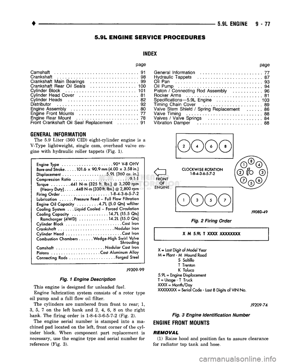
The 5.9 Liter (360 CID) eight-cylinder engine is a
V-Type lightweight, single cam, overhead valve en
gine with hydraulic roller tappets (Fig. 1).
Engine Type .90° V-8 OHV
Bore and Stroke 101.6 x 90.9
mm
(4.00 x 3.58 in.)
Displacement 5.9L (360 cu. in.)
Compression Ratio 9.1:1
Torque 441 N-m (325 ft. lbs.) @ 3,200 rpm (Heavy Duty). 448 N-m (330 ft. lbs.)
@
2,800 rpm
Firing Order
1-8-4-3-6-5-7-2
Lubrication ...... Pressure Feed - Full Flow Filtration
Engine Oil Capacity .4.7L (5.0 Qts) w/filter
Cooling System . .
.
Liquid Cooled - Forced Circulation Cooling Capacity ..... . . 14.7L (15.5 Qts)
Ramcharger (4WD) 14.2L (15.0 Qts)
Cylinder Block Cast Iron Crankshaft
-
Nodular Iron
Cylinder Head • . Cast Iron Combustion Chambers Wedge-High Swirl Valve
Shrouding
Camshaft Nodular Cast Iron Pistons Cast Aluminum Alloy
Connecting Rods Forged Steel
J9309-99
Fig. 1
Engine
Description
This engine is designed for unleaded fuel.
Engine lubrication system consists of a rotor type
oil pump and a full flow oil filter.
The cylinders are numbered from front to rear; 1,
3,
5, 7 on the left bank and 2, 4, 6, 8 on the right
bank. The firing order is
1-8-4-3-6-5-7-2
(Fig. 2).
The engine serial number is stamped into a ma
chined pad located on the left, front corner of the cyl
inder block. When component part replacement is
necessary, use the engine type and serial number for
reference (Fig. 3).
o
FRONT OF
ENGINE CLOCKWISE ROTATION
1-8-4-3-6-5-7-2
J908D-49
Fig. 2 Firing Order
X
M 5.9L T
XXXX
XXXXXXXX
X
= Last Digit of Model Year
M = Plant - M Mound Road S Saltillo
T Trenton K Toluca
5.9L = Engine Displacement
T
= Usage -
T
Truck
XXXX
= Month/Day
XXXXXXXX
= Serial Code - Last 8 Digits of
VIN
No.
J9209-74
Fig.
3
Engine
identification
Number
ENGINE
FRONT MOUNTS
REMOVAL (1) Raise hood and position fan to assure clearance
for radiator top tank and hose.
Page 701 of 1502
9
- 96 5.9L
ENGINE
•
Fig.
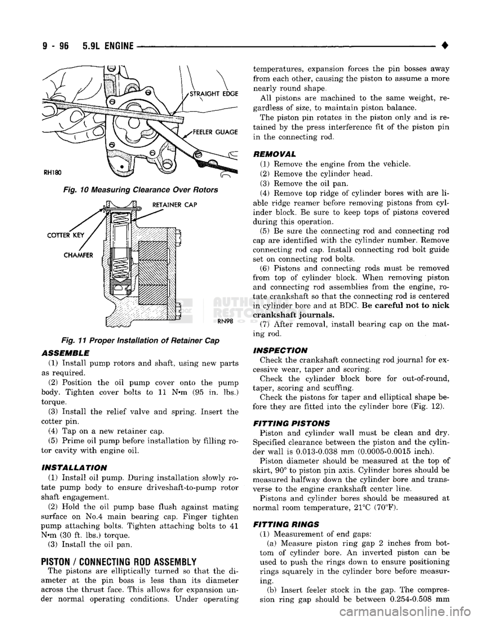
11 Proper installation of Retainer Cap
ASSEMBLE
(1)
Install pump rotors and shaft, using new parts
as required.
(2)
Position the oil pump cover onto the pump
body. Tighten cover bolts to 11 N-m (95 in. lbs.) torque.
(3)
Install the relief valve and spring. Insert the
cotter pin.
(4)
Tap on a new retainer cap.
(5)
Prime oil pump before installation by filling ro
tor cavity with engine oil.
INSTALLATION
(1) Install oil pump. During installation slowly ro
tate pump body to ensure driveshaft-to-pump rotor shaft engagement.
(2)
Hold the oil pump base flush against mating
surface on No.4 main bearing cap. Finger tighten
pump attaching bolts. Tighten attaching bolts to 41 N-m (30 ft. lbs.) torque.
(3)
Install the oil pan.
PISTON
/
CONNECTING ROD ASSEMBLY
The pistons are elliptically turned so that the di
ameter at the pin boss Is less than its diameter
across the thrust face. This allows for expansion un
der normal operating conditions. Under operating temperatures, expansion forces the pin bosses away
from each other, causing the piston to assume a more
nearly round shape.
All pistons are machined to the same weight, re
gardless of size, to maintain piston balance.
The piston pin rotates in the piston only and is re
tained by the press interference fit of the piston pin in the connecting rod.
REMOVAL
(1) Remove the engine from the vehicle.
(2) Remove the cylinder head.
(3) Remove the oil pan.
(4)
Remove top ridge of cylinder bores with are li
able ridge reamer before removing pistons from cyl
inder block. Be sure to keep tops of pistons covered
during this operation.
(5)
Be sure the connecting rod and connecting rod
cap are identified with the cylinder number. Remove
connecting rod cap. Install connecting rod bolt guide
set on connecting rod bolts. (6) Pistons and connecting rods must be removed
from top of cylinder block. When removing piston and connecting rod assemblies from the engine, ro
tate crankshaft so that the connecting rod is centered in cylinder bore and at BDC. Be careful not to nick crankshaft journals. (7) After removal, install bearing cap on the mat
ing rod.
INSPECTION Check the crankshaft connecting rod journal for ex
cessive wear, taper and scoring. Check the cylinder block bore for out-of-round,
taper, scoring and scuffing. Check the pistons for taper and elliptical shape be
fore they are fitted into the cylinder bore (Fig. 12).
FITTING PISTONS Piston and cylinder wall must be clean and dry.
Specified clearance between the piston and the cylin
der wall is 0.013-0.038 mm
(0.0005-0.0015
inch).
Piston diameter should be measured at the top of
skirt, 90° to piston pin axis. Cylinder bores should be
measured halfway down the cylinder bore and trans
verse to the engine crankshaft center line.
Pistons and cylinder bores should be measured at
normal room temperature, 21°C (70°F).
FITTING RINGS (1) Measurement of end gaps:
(a) Measure piston ring gap 2 inches from bot
tom of cylinder bore. An inverted piston can be used to push the rings down to ensure positioning
rings squarely in the cylinder bore before measur ing.
(b) Insert feeler stock in the gap. The compres
sion ring gap should be between
0.254-0.508
mm
Page 703 of 1502
(2) Before installing the ring compressor, make
sure the oil ring expander ends are butted and the
rail gaps located properly (Fig. 14).
(3) Immerse the piston head and rings in clean en
gine oil. Slide Piston Ring Compressor Tool C-385
over the piston and tighten with the special wrench (part of Tool C-385). Be
sure position
of
rings does
not change
during this operation.
(4) Install connecting rod bolt protectors on rod
bolts,
the long protector should be installed on the numbered side of the connecting rod. (5) Rotate crankshaft so that the connecting rod
journal is on the center of the cylinder bore. Be sure connecting rod and cylinder bore number are the same. Insert rod and piston into cylinder bore and
guide rod over the crankshaft journal.
(6) Tap the piston down in cylinder bore, using a
hammer handle. At the same time, guide connecting
rod into position on crankshaft journal. (7) The notch or groove on top of piston must be
pointing toward front of engine. The larger chamfer of the connecting rod bore must be Installed toward
crankshaft journal fillet.
(8) Install rod caps. Install nuts on cleaned and
oiled rod bolts and tighten nuts to 61 N*m (45 ft. lbs.)
torque. (9) Install the oil pan.
(10) Install the cylinder head.
(11) Install the engine Into the vehicle.
CRANKSHAFT
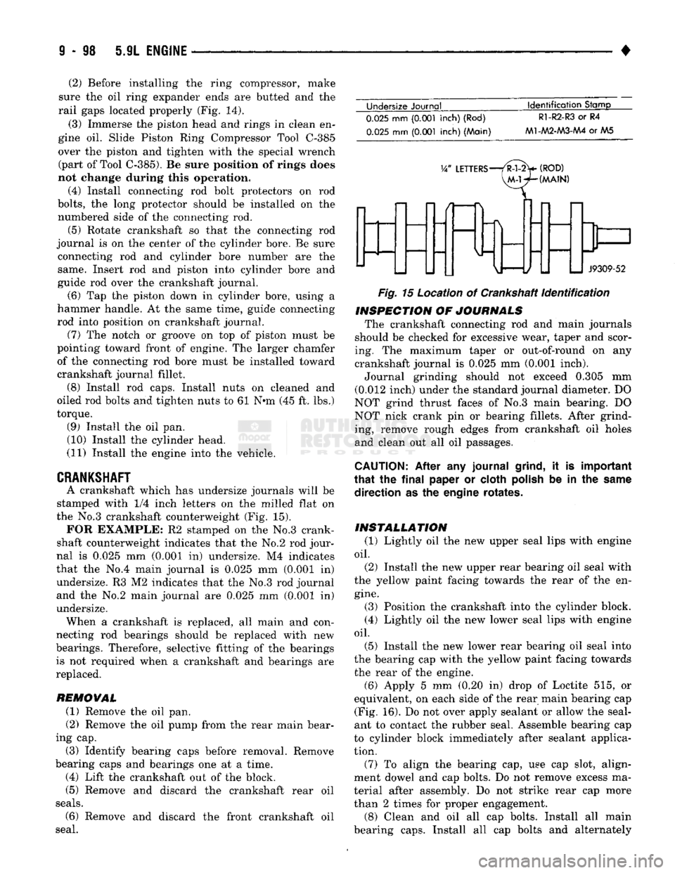
A crankshaft which has undersize journals will be
stamped with 1/4 inch letters on the milled flat on
the No.3 crankshaft counterweight (Fig. 15). FOR EXAMPLE: R2 stamped on the No.3 crank
shaft counterweight indicates that the No.2 rod jour
nal is 0.025 mm (0.001 in) undersize. M4 indicates
that the No.4 main journal is 0.025 mm (0.001 in) undersize. R3 M2 indicates that the No.3 rod journal
and the No.2 main journal are 0.025 mm (0.001 In)
undersize. When a crankshaft is replaced, all main and con
necting rod bearings should be replaced with new
bearings. Therefore, selective fitting of the bearings is not required when a crankshaft and bearings are
replaced.
REMOVAL
(1) Remove the oil pan.
(2) Remove the oil pump from the rear main bear
ing cap.
(3) Identify bearing caps before removal. Remove
bearing caps and bearings one at a time. (4) Lift the crankshaft out of the block.
(5) Remove and discard the crankshaft rear oil
seals.
(6) Remove and discard the front crankshaft oil
seal. Undersize Journal
Identification
Stamp
0.025
mm
(0.001
inch) (Rod)
0.025
mm
(0.001
inch) (Main)
R1-R2-R3
or R4
M1-AA2-M3-AA4
or AA5
V/
LETTERS—/R-l-2>
(ROD)
VM-WHMAIN)
J9309-52
Fig.
15 Location of Crankshaft
identification
INSPECTION
OF
JOURNALS
The crankshaft connecting rod and main journals
should be checked for excessive wear, taper and scor
ing. The maximum taper or out-of-round on any
crankshaft journal is 0.025 mm (0.001 inch).
Journal grinding should not exceed 0.305 mm
(0.012 inch) under the standard journal diameter. DO
NOT grind thrust faces of No.3 main bearing. DO
NOT nick crank pin or bearing fillets. After grind ing, remove rough edges from crankshaft oil holes
and clean out all oil passages.
CAUTION:
After any journal
grind,
it is important
that
the
final
paper or cloth
polish
be in the
same
direction as the engine rotates.
INSTALLATION
(1) Lightly oil the new upper seal lips with engine
oil.
(2) Install the new upper rear bearing oil seal with
the yellow paint facing towards the rear of the en
gine.
(3) Position the crankshaft into the cylinder block.
(4) Lightly oil the new lower seal lips with engine
oil.
(5) Install the new lower rear bearing oil seal into
the bearing cap with the yellow paint facing towards the rear of the engine. (6) Apply 5 mm (0.20 in) drop of Loctite 515, or
equivalent, on each side of the rear main bearing cap (Fig. 16). Do not over apply sealant or allow the seal
ant to contact the rubber seal. Assemble bearing cap
to cylinder block immediately after sealant applica
tion.
(7) To align the bearing cap, use cap slot, align
ment dowel and cap bolts. Do not remove excess ma
terial after assembly. Do not strike rear cap more
than 2 times for proper engagement.
(8) Clean and oil all cap bolts. Install all main
bearing caps. Install all cap bolts and alternately
Page 708 of 1502
— 5.9L
ENGINE
9 - 103
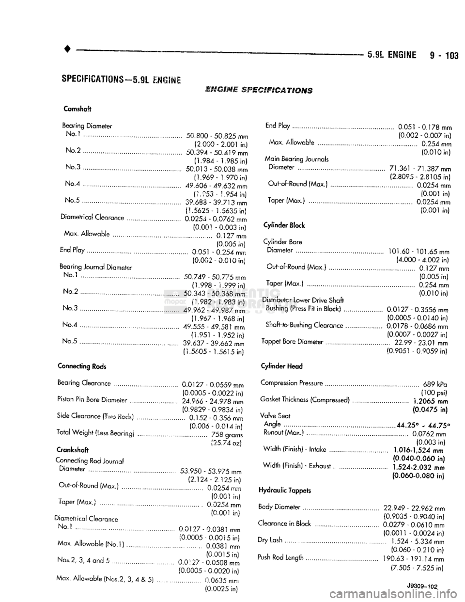
SPECIFICATIONS—5.9L
ENGINE
EmmmE
SPECIFICATIONS
Camshaft
Bearing
Diameter
No i 50.800 - 50.825 mm "" (2.000 - 2.001 in)
No2
50.394-50.419 mm
' (1.984- 1.985 in)
No 3 50.013 - 50.038 mm
(1.969- 1 970 in)
No
4 49.606 - 49.632 mm
(1.953 - 1.954 in)
No
5 ................ 39.683 -39.713 mm
(1.5625-
1.5635 in)
Diametrical
Clearance 0.0254 - 0.0762 mm
(0.001 - 0.003 in)
Max.
Allowable
. 0.127 mm (0.005 in)
End
p|ay 0.051 - 0.254 mm
(0.002-0.010 in)
Bearinq
Journal
Diameter
No i 50.749 - 50.775 mm (1.998- 1.999 in)
No
2 50.343 - 50.368 mm
(1.982-
1.983 in)
No
3 . .............. 49.962 - 49.987 mm (1.967- 1.968 in)
No
4 . 49.555-49.581 mm
(1.951
- 1 952 in)
No
5 39.637 - 39.662 mm
(1.5605-
1.5615 in)
Connecting
Rods
Bearing Clearance 0.0127 - 0.0559 mm (0.0005 - 0.0022 in)
Piston Pin Bore
Diameter
24.966 - 24.978 mm
(0.9829 - 0.9834 in)
Side
Clearance (Two
Rods)
......................... 0.152 - 0.356 mm
(0.006-0.014 in)
Total
Weight
(Less
Bearing) . ... • 758 grams
(25.74 oz)
Crankshaft
Connecting
Rod
Journal
Diameter
. 53.950 - 53.975 mm (2.124 - 2.125 in)
Out-of-Round (Max.) 0.0254 mm
(0.001 in)
Taper (Max.) ... 0.0254 mm
(0.001 in)
Diametrical
Clearance
No
1
... ........ 0.0127 - 0.0381 mm (0.0005-0.0015 in)
Max
Allowable
(No.l)
- 0.0381 mm
(0.0015 in)
Nos.2,
3, 4 and 5 0.0127 - 0.0508 mm
(0.0005 - 0.0020 in)
Max.
Allowable
(Nos.2,
3, 4 & 5) ...... - 0.0635 mm (0.0025 in)
End
Play 0.051 -0.178 mm
(0.002 - 0.007 in)
Max.
Allowable
0.254 mm
(0.010 in)
Main Bearing Journals
Diameter
71.361 - 71.387 mm
(2.8095-
2.8105 in)
Out-of-Round (Max.) 0.0254 mm
(0.001 in)
Taper (Max.) .., 0.0254 mm
(0.001 in)
Cylinder Block
Cylinder
Bore
Diameter
, 101.60 - 101.65 mm (4.000 - 4.002 in)
Out-of-Round (Max.) ........... 0.127 mm
(0.005 in)
Taper (Max.) 0.254 mm
(0.010 in)
Distributor
Lower
Drive
Shaft
Bushing (Press Fit in Block) 0.0127 - 0.3556 mm (0.0005-0.0140 in)
Shaft-to-Bushing Clearance 0.0178 - 0.0686 mm (0.0007 - 0,0027 in)
Tappet
Bore
Diameter
.............. 22.99 - 23.01 mm (0.9051 - 0.9059 in)
Cylinder Head
Compression Pressure 689 kPa (100 psi)
Gasket Thickness (Compressed)
1.2065
mm
(0.0475 In)
Valve Seat
Angle .
44.25°
- 44.75° Runout (Max.) ....................... 0.0762 mm (0.003 in)
Width
(Finish) -
Intake
1.016-1.524
mm (0,040-0.060 in)
Width
(Finish) - Exhaust
1.524-2.032
mm
(0.060-0.080
in)
Hydraulic Tappets
Body
Diameter
22.949 - 22.962 mm (0.9035 - 0.9040 in)
Clearance in Block 0.0279 - 0.0610 mm
(0.0011 - 0.0024 in)
Dry
Lash
. 1.524 - 5.334 mm
(0.060-0210 in)
Push
Rod
Length
190.63 - 191.14mm
(7.505 - 7.525 in)
J9309-102
Page 709 of 1502
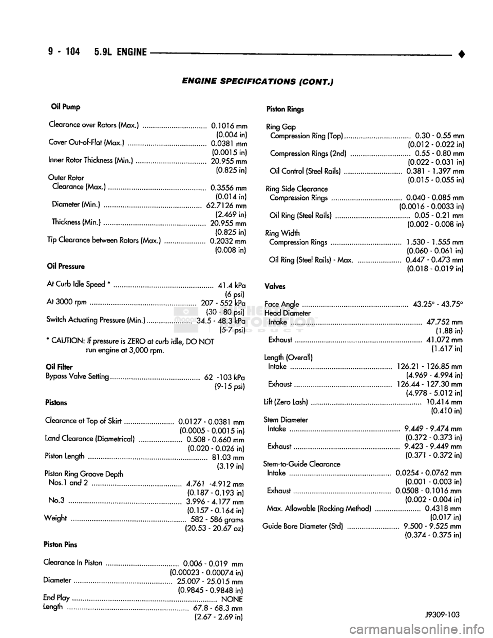
9 - 104 5.9L ENGINE
• ENGINE
SPECIFICATIONS
(CONT„)
Oil
Pump
Clearance over Rotors (Max.) 0.1016 mm (0.004 in)
Cover Out-of-Flat (Max.)
0.0381
mm (0.0015 in)
Inner Rotor Thickness (Min.) 20.955 mm
(0.825 in)
Outer Rotor
Clearance (Max.) 0.3556 mm (0.014 in)
Diameter (Min.) 62.7126 mm (2.469 in)
Thickness (Min.) 20.955 mm (0.825 in)
Tip Clearance between Rotors (Max.) 0.2032 mm (0.008 in)
Oil
Pressure
At Curb Idle Speed
*
41.4 kPa (6 psi)
At
3000 rpm 207 - 552 kPa (30 - 80 psi)
Switch Actuating Pressure (Min.) 34.5 - 48.3 kPa (5-7 psi)
* CAUTION: If pressure is ZERO at curb idle, DO NOT run engine at
3,000
rpm.
Oil
Filter
Bypass Valve Setting 62 -103 kPa (9-15 psi)
Pistons
Clearance at
Top
of Skirt 0.0127
-
0.0381
mm (0.0005-0.0015 in)
Land Clearance (Diametrical)
0.508
-
0.660
mm (0.020 -
0.026
in)
Piston Length 81.03 mm (3.19 in)
Piston Ring Groove Depth
Nos.l and 2 4.761 -4.912 mm (0.187-0.193 in)
No.3 3.996-4.177
mm
(0.157-0.164 in)
Weight 582 - 586 grams (20.53 - 20.67 oz)
Piston
Pins
Clearance In Piston
0.006
- 0.019 mm (0.00023 - 0.00074 in)
Diameter 25.007
-
25.015 mm
(0.9845 - 0.9848 in)
End Play NONE
Length 67.8 - 68.3 mm (2.67
-
2.69 in)
Piston
Rings
Ring Gap
Compression Ring (Top) 0.30 - 0.55 mm (0.012-0.022 in)
Compression Rings (2nd) 0.55 - 0.80 mm (0.022 - 0.031 in)
Oil Control (Steel Rails) 0.381 - 1.397 mm (0.015-0.055 in)
Ring Side Clearance Compression Rings
0.040
-
0.085
mm (0.0016-0.0033 in)
Oil Ring (Steel Rails) 0.05 - 0.21 mm (0.002 -
0.008
in)
Ring Width Compression Rings 1.530 - 1.555 mm (0.060 - 0.061 in)
Oil Ring (Steel Rails) - Max
0.447
-
0.473
mm (0.018-0.019 in)
Valves
Face Angle 43.25° - 43.75°
Head Diameter Intake 47.752 mm (1.88 in)
Exhaust 41.072 mm
(1.617 in)
Length (Overall) Intake 126.21 - 126.85 mm
(4.969 - 4.994 in)
Exhaust 126.44 - 127.30 mm
(4.978-5.012 in)
Lift (Zero Lash) 10.414 mm
(0.410 in)
Stem Diameter Intake
9.449
-
9.474
mm
(0.372 -
0.373
in)
Exhaust
9.423
-
9.449
mm
(0.371 -
0.372
in)
Stem-to-Guide Clearance Intake 0.0254 - 0.0762 mm (0.001 -
0.003
in)
Exhaust 0.0508-0.1016 mm
(0.002 -
0.004
in)
Max. Allowable (Rocking Method) 0.4318 mm (0.017 in)
Guide Bore Diameter (Std)
9.500
-
9.525
mm (0.374 -
0.375
in) J9309-103
Page 710 of 1502
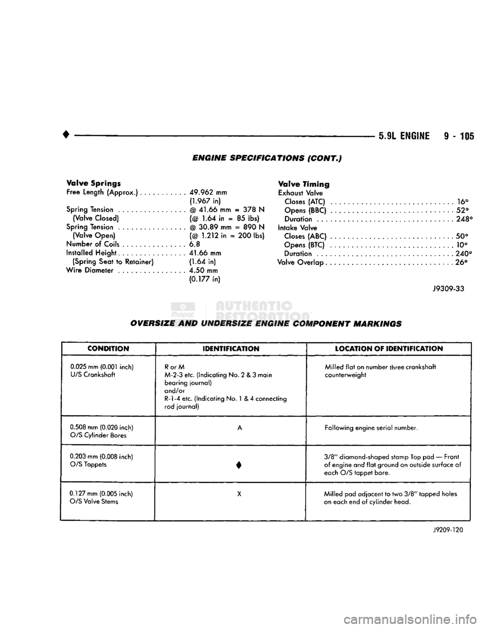
5.9L
ENGINE
9 - 105
ENGINE SPECIFICATIONS
(CONT.J
Valve
Springs
Free Length
(Approx.)...........
49.962
mm f1.967 in)
Spring
Tension ................ @ 41.66 mm = 378 N
(Valve Closed) (@ 1.64 in « 85 lbs)
Spring
Tension @ 30.89 mm = 890 N (Valve Open) (@ 1.212 in = 200 lbs)
Number of Coils ............... 6.8
Installed Height 41.66 mm (Spring Seat to Retainer) (1.64 in)
Wire Diameter ................ 4.50 mm
(0.177
in) Valve
Timing
Exhaust
Valve
Closes
(ATC) ............. 16°
Opens
(BBC) .................. ....... 52° Duration 248°
Intake Valve
Closes
(ABC) 50°
Opens
(BTC) 10° Duration ................. 240°
Valve Overlap.............................. 26°
J9309-33
OVERSIZE
AND
UNDERSIZE
ENGINE COMPONENT MARKINGS
CONDITION
IDENTIFICATION
LOCATION
OF
IDENTIFICATION
0.025
mm
(0.001
inch)
U/S
Crankshaft
RorM
M-2-3 etc. (Indicating No. 2 & 3 main bearing journal)
and/or
R-l-4 etc. (Indicating No. 1 & 4 connecting
rod journal) Milled
flat
on number
three
crankshaft
counterweight
0.508
mm
(0.020
inch)
O/S
Cylinder Bores
A
Following engine serial number.
0.203
mm
(0.008
inch)
O/S
Tappets • 3/8" diamond-shaped stamp Top pad — Front
of engine and
flat
ground on outside surface of
each O/S tappet bore.
0.127 mm
(0.005
inch)
O/S
Valve Stems
X
Milled pad adjacent to two 3/8" tapped holes
on
each end of cylinder head.
J9209-120