4WD DODGE TRUCK 1993 Service Service Manual
[x] Cancel search | Manufacturer: DODGE, Model Year: 1993, Model line: TRUCK, Model: DODGE TRUCK 1993Pages: 1502, PDF Size: 80.97 MB
Page 714 of 1502
•
5.9L
(DIESEL) ENGINE
9 - 109 (5) Raise the rear of the transmission and engine
SLIGHTLY.
(6)
Remove the mounting bolts and nuts. Remove
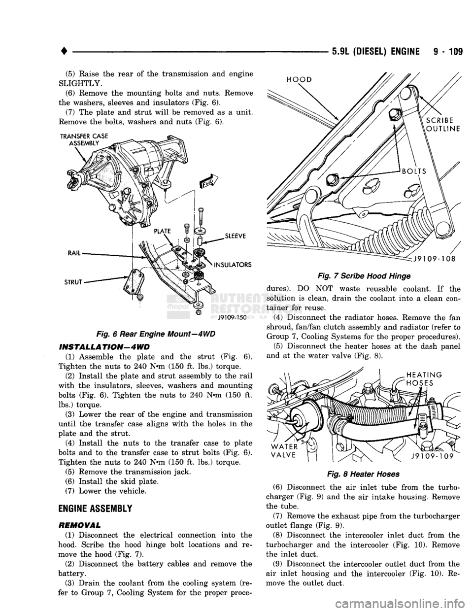
the washers, sleeves and insulators (Fig. 6). (7) The plate and strut will be removed as a unit.
Remove the bolts, washers and nuts (Fig. 6).
J9109-150
Fig.
6 Rear
Engine
Mount—4WD
INSTALL A
TION—4
WD
(1) Assemble the plate and the strut (Fig. 6).
Tighten the nuts to 240 N-m (150 ft. lbs.) torque.
(2) Install the plate and strut assembly to the rail
with the insulators, sleeves, washers and mounting
bolts (Fig. 6). Tighten the nuts to 240 N-m (150 ft. lbs.) torque.
(3) Lower the rear of the engine and transmission
until the transfer case aligns with the holes in the
plate and the strut.
(4) Install the nuts to the transfer case to plate
bolts and to the transfer case to strut bolts (Fig. 6). Tighten the nuts to 240 N-m (150 ft. lbs.) torque.
(5) Remove the transmission jack.
(6) Install the skid plate.
(7) Lower the vehicle.
ENGINE
ASSEMBLY
REMOVAL
(1) Disconnect the electrical connection into the
hood. Scribe the hood hinge bolt locations and re
move the hood (Fig. 7).
(2) Disconnect the battery cables and remove the
battery.
(3) Drain the coolant from the cooling system (re
fer to Group 7, Cooling System for the proper proce-
Fig.
7
Scribe
Hood
Hinge
dures).
DO NOT waste reusable coolant. If the
solution is clean, drain the coolant into a clean con
tainer for reuse.
(4) Disconnect the radiator hoses. Remove the fan
shroud, fan/fan clutch assembly and radiator (refer to
Group 7, Cooling Systems for the proper procedures). (5) Disconnect the heater hoses at the dash panel
and at the water valve (Fig. 8).
Fig.
8 Heater
Hoses
(6) Disconnect the air inlet tube from the turbo
charger (Fig. 9) and the air intake housing. Remove
the tube.
(7) Remove the exhaust pipe from the turbocharger
outlet flange (Fig. 9).
(8) Disconnect the intercooler inlet duct from the
turbocharger and the intercooler (Fig. 10). Remove
the inlet duct.
(9) Disconnect the intercooler outlet duct from the
air inlet housing and the intercooler (Fig. 10). Re
move the outlet duct.
Page 790 of 1502
•
FRAME
AND
BUMPERS
13 - 3
SNOW
PLOW
NDEX
page
Power
Angling Cylinder Service
16
Power
Unit
. . 13
Service
Information
3
Snow
Plow Control Module
17
Snow
Plow Frame
16
SERVICE
INFORMATION
A snow plow is optionally available for 4WD Ram
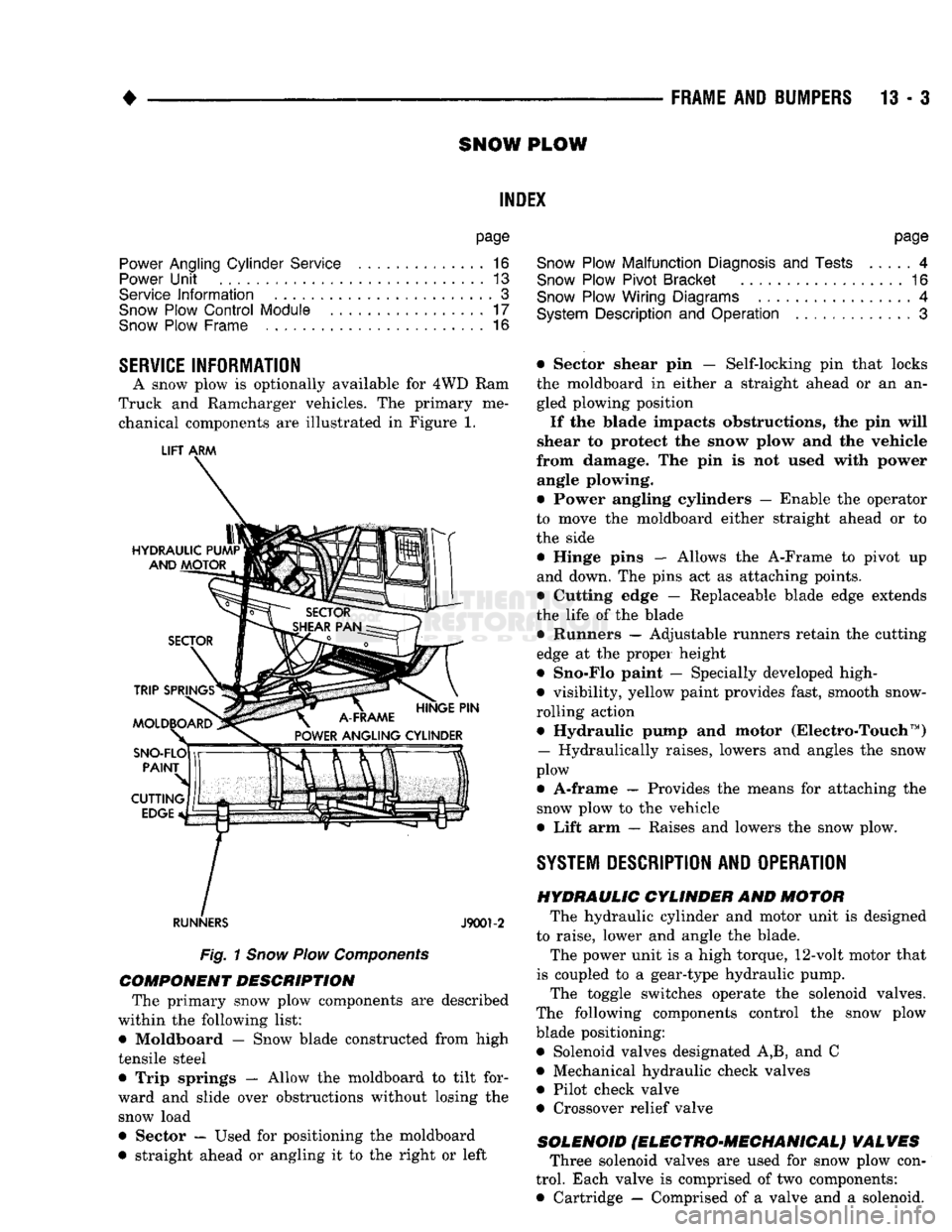
Truck and Ramcharger vehicles. The primary me chanical components are illustrated in Figure 1.
LIFT
ARM
RUNNERS
J9001-2
Fig.
1
Snow
Plow
Components
COMPONENT DESCRIPTION
The primary snow plow components are described
within the following list:
• Moldboard — Snow blade constructed from high
tensile steel
• Trip springs — Allow the moldboard to tilt for
ward and slide over obstructions without losing the snow load
• Sector — Used for positioning the moldboard
• straight ahead or angling it to the right or left
page
Snow
Plow Malfunction
Diagnosis
and
Tests
4
Snow
Plow Pivot Bracket
16
Snow
Plow Wiring Diagrams
4
System
Description
and
Operation
3
• Sector shear pin — Self-locking pin that locks the moldboard in either a straight ahead or an an
gled plowing position
If the blade impacts obstructions, the pin will
shear to protect the snow plow and the vehicle
from damage. The pin is not used with power angle plowing.
• Power angling cylinders — Enable the operator
to move the moldboard either straight ahead or to
the side
• Hinge pins — Allows the A-Frame to pivot up
and down. The pins act as attaching points.
• Cutting edge — Replaceable blade edge extends
the life of the blade • Runners — Adjustable runners retain the cutting
edge at the proper height
• Sno-Flo paint — Specially developed high-
• visibility, yellow paint provides fast, smooth snow-
rolling action • Hydraulic pump and motor (Electro-Touch ™)
— Hydraulically raises, lowers and angles the snow
plow
• A-frame — Provides the means for attaching the snow plow to the vehicle
• Lift arm — Raises and lowers the snow plow.
SYSTEM
DESCRIPTION
AND OPERATION HYDRAULIC CYLINDER
AND
MOTOR
The hydraulic cylinder and motor unit is designed
to raise, lower and angle the blade. The power unit is a high torque, 12-volt motor that
is coupled to a gear-type hydraulic pump. The toggle switches operate the solenoid valves.
The following components control the snow plow blade positioning: • Solenoid valves designated A,B, and C
• Mechanical hydraulic check valves
• Pilot check valve
• Crossover relief valve
SOLENOID
fELEGTRO'MEGHANIGALj VALVES
Three solenoid valves are used for snow plow con
trol. Each valve is comprised of two components:
• Cartridge — Comprised of a valve and a solenoid.
Page 807 of 1502
13
- 20 FRAME AND IUMPERS
• FRAME
INDEX
page
Frame
Inspection/Measurements 25
Frame
Repair 29 General
Information
page
. . 20
GENERAL INFORMATION
DESIGN
Ram Truck, Chassis Cab and Ramcharger vehicles
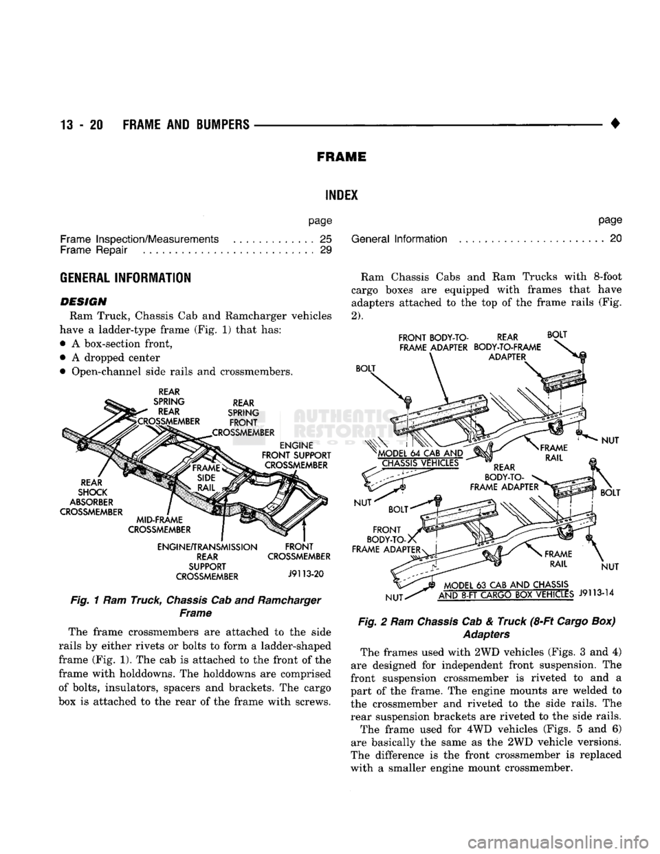
have a ladder-type frame (Fig. 1) that has:
• A box-section front,
• A dropped center
• Open-channel side rails and crossmembers.
REAR
SPRING REAR REAR SPRING
^CROSSMEMBER
FRONT
.CROSSMEMBER ENGINE
FRONT
SUPPORT CROSSMEMBER
REAR
SHOCK
ABSORBER
CROSSMEMBER MID-FRAME
CROSSMEMBER
ENGINE/TRANSMISSION REAR
SUPPORT
CROSSMEMBER
FRONT
CROSSMEMBER
J9113-20
Fig.
1 Ram Truck,
Chassis
Cab and
Ramcharger
Frame
The frame crossmembers are attached to the side
rails by either rivets or bolts to form a ladder-shaped
frame (Fig. 1). The cab is attached to the front of the
frame with holddowns. The holddowns are comprised
of bolts, insulators, spacers and brackets. The cargo
box is attached to the rear of the frame with screws. Ram Chassis Cabs and Ram Trucks with
8-foot
cargo boxes are equipped with frames that have
adapters attached to the top of the frame rails (Fig.
2).
FRONT
BODY-TO-
FRAME ADAPTER REAR
BODY-TO-FRAME
ADAPTER
BOLT
BOLT
>
KAC MODEL
64
CAB
AND
CHASSIS VEHICLES
NUT REAR
BODY-TO-
FRAME ADAPTER
BOLT
FRONT
BODY-TO-x
FRAME ADAPTER
NUT NUT
BOLT
NUT
MODEL
63
CAB
AND
CHASSIS
AND
8-FT
CARGO
BOX
VEHICLES
J9113-14
Fig.
2 Ram
Chassis
Cab & Truck (8-Ft
Cargo
Box) Adapters The frames used with
2WD
vehicles (Figs. 3 and 4)
are designed for independent front suspension. The
front suspension crossmember is riveted to and a
part of the frame. The engine mounts are welded to
the crossmember and riveted to the side rails. The
rear suspension brackets are riveted to the side rails.
The frame used for 4WD vehicles (Figs. 5 and 6)
are basically the same as the
2WD
vehicle versions.
The difference is the front crossmember is replaced
with a smaller engine mount crossmember.
Page 812 of 1502
FRAME
AND
BUMPERS
13 - 25
FUNCTION
The frame is the foundation and the structural cen
ter of the vehicle. The primary function of a frame is
to provide support and attachment locations: • For all the chassis/drivetrain components
• For the cab/body
• For the vehicle payload While limiting deflections and twisting of the
frame members. The frame maintains the correct relationship and
alignment of the powertrain. This relationship and
alignment ensures normal operation of the attached
units.
CONSTRUCTION MATERIAL High-strength, carbon steel with a minimum yield
strength of 32,000 psi is used to construct frame side
rails.
A frame made of 32,000 psi minimum yield
strength steel has, in reality, a range of 32,000 to
44,000 psi yield strength.
For 4WD vehicle applications, the frame side rails
reinforcements are constructed of the same high- strength, carbon steel as the side rails.
BENDING RESISTANCE A frame reacts to its load and the road surface de
viations by deflecting and twisting. The primary de
flecting frame members are the side rails. Resistance
to frame twist is provided by the crossmembers.
FRAME
INSPECTION/MEASUREMENTS
INSPECTION Inspect the frame members for visible damage and
metal deformations. Inspect all riveted, bolted and
welded connections for looseness and/or missing hardware. All damaged areas must be repaired and/or the
frame members replaced, as necessary.
MEASUREMENTS Measure the frame for mis-alignment with the cab/
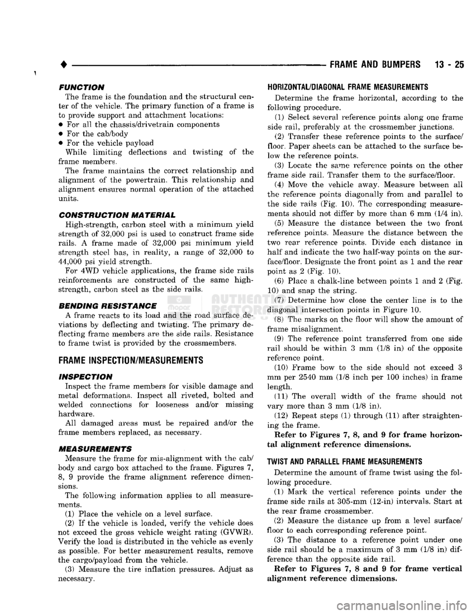
body and cargo box attached to the frame. Figures 7, 8, 9 provide the frame alignment reference dimen
sions.
The following information applies to all measure
ments.
(1) Place the vehicle on a level surface.
(2) If the vehicle is loaded, verify the vehicle does
not exceed the gross vehicle weight rating (GVWR).
Verify the load is distributed in the vehicle as evenly as possible. For better measurement results, remove
the cargo/payload from the vehicle.
(3) Measure the tire inflation pressures. Adjust as
necessary.
HORIZONTAL/DIAGONAL
FRAME MEASUREMENTS
Determine the frame horizontal, according to the
following procedure.
(1) Select several reference points along one frame
side rail, preferably at the crossmember junctions.
(2) Transfer these reference points to the surface/
floor. Paper sheets can be attached to the surface be low the reference points.
(3) Locate the same reference points on the other
frame side rail. Transfer them to the surface/floor.
(4) Move the vehicle away. Measure between all
the reference points diagonally from and parallel to
the side rails (Fig. 10). The corresponding measure ments should not differ by more than 6 mm (1/4 in).
(5)
Measure the distance between the two front
reference points. Measure the distance between the
two rear reference points. Divide each distance in
half and indicate the two half-way points on the sur
face/floor. Designate the front point as 1 and the rear
point as 2 (Fig. 10).
(6) Place a chalk-line between points 1 and 2 (Fig.
10) and snap the string.
(7) Determine how close the center line is to the
diagonal intersection points in Figure 10.
(8) The marks on the floor will show the amount of
frame misalignment.
(9) The reference point transferred from one side
rail should be within 3 mm (1/8 in) of the opposite
reference point.
(10) Frame bow to the side should not exceed 3
mm per 2540 mm (1/8 inch per 100 inches) in frame
length.
(11) The overall width of the frame should not
vary more than 3 mm (1/8 in). (12) Repeat steps (1) through (11) after straighten
ing the frame.
Refer to Figures 7, 8, and 9 for frame horizon
tal alignment reference dimensions.
TWIST
AND PARALLEL FRAME MEASUREMENTS
Determine the amount of frame twist using the fol
lowing procedure.
(1) Mark the vertical reference points under the
frame side rails at 305-mm (12-in) intervals. Start at
the rear frame crossmember.
(2) Measure the distance up from a level surface/
floor to each corresponding reference point. (3) The distance to a reference point under one
side rail should be a maximum of 3 mm (1/8 in)
dif
ference than the opposite side rail.
Refer to Figures 7, 8 and 9 for frame vertical
alignment reference dimensions.
Page 817 of 1502
13
- 30 FRAME AND BUMPERS
ATTACHED COMPONENTS
SKID
PLATES
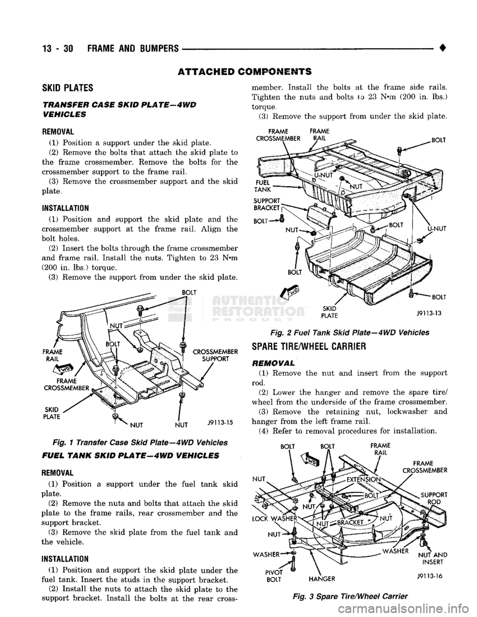
TRANSFER CASE SKID
PL
ATF
4 WD
VEHICLES
REMOVAL
(1) Position
a
support under
the
skid plate.
(2) Remove
the
bolts that attach
the
skid plate
to
the frame crossmember. Remove
the
bolts
for the
crossmember support
to the
frame rail.
(3) Remove
the
crossmember support
and the
skid
plate.
INSTALLATION
(1) Position
and
support
the
skid plate
and the
crossmember support
at the
frame rail. Align
the
bolt holes.
(2) Insert
the
bolts through
the
frame crossmember
and frame rail. Install
the
nuts. Tighten
to 23 N*m
(200
in. lbs.)
torque.
(3) Remove
the
support from under
the
skid plate.
Fig.
1
Transfer
Case Skid
Plate—4WD Vehicles
FUEL TANK SKID
PLATE-4WD
VEHICLES
REMOVAL
(1) Position
a
support under
the
fuel tank skid
plate.
(2) Remove
the
nuts
and
bolts that attach
the
skid
plate
to the
frame rails, rear crossmember
and the
support bracket.
(3) Remove
the
skid plate from
the
fuel tank
and
the vehicle.
INSTALLATION
(1) Position
and
support
the
skid plate under
the
fuel tank. Insert
the
studs
in the
support bracket.
(2) Install
the
nuts
to
attach
the
skid plate
to the
support bracket. Install
the
bolts
at the
rear cross- member. Install
the
bolts
at the
frame side rails.
Tighten
the
nuts
and
bolts
to 23 N*m (200 in. lbs.)
torque.
(3) Remove
the
support from under
the
skid plate.
FRAME FRAME
Fig.
2
Fuel
Tank
Skid
Plate-4WD Vehicles
SPARE
TIRE/WHEEL
CARRIER
REMOVAL
(1) Remove
the nut and
insert from
the
support
rod. (2) Lower
the
hanger
and
remove
the
spare tire/
wheel from
the
underside
of the
frame crossmember.
(3) Remove
the
retaining
nut,
lockwasher
and
hanger from
the
left frame rail.
(4) Refer
to
removal procedures
for
installation. BOLT BOLT FRAME
Fig.
3
Spare
The/Wheel Carrier
Page 854 of 1502
•
FUEL SYSTEM
14 - 35
SENSOR
RETURN—PCM
INPUT
Sensor Return provides a low noise ground refer
ence for all system sensors.
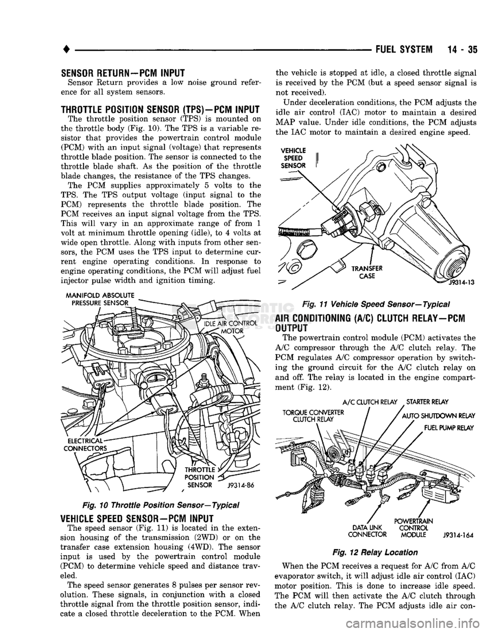
THROTTLE POSITION
SENSOR
(TPS)-PCM
INPUT
The throttle position sensor (TPS) is mounted on
the throttle body (Fig. 10). The TPS is a variable re sistor that provides the powertrain control module (PCM) with an input signal (voltage) that represents
throttle blade position. The sensor is connected to the
throttle blade shaft. As the position of the throttle
blade changes, the resistance of the TPS changes. The PCM supplies approximately 5 volts to the
TPS.
The TPS output voltage (input signal to the PCM) represents the throttle blade position. The
PCM receives an input signal voltage from the TPS.
This will vary in an approximate range of from 1
volt at minimum throttle opening (idle), to 4 volts at
wide open throttle. Along with inputs from other sen
sors,
the PCM uses the TPS input to determine cur
rent engine operating conditions. In response to
engine operating conditions, the PCM will adjust fuel
injector pulse width and ignition timing.
MANIFOLD ABSOLUTE
Fig.
10
Throttle
Position Sensor—Typical
VEHICLE
SPEED
SENSOR—PCM
INPUT
The speed sensor (Fig. 11) is located in the exten
sion housing of the transmission (2WD) or on the
transfer case extension housing (4WD). The sensor input is used by the powertrain control module (PCM) to determine vehicle speed and distance trav
eled. The speed sensor generates 8 pulses per sensor rev
olution. These signals, in conjunction with a closed
throttle signal from the throttle position sensor, indi
cate a closed throttle deceleration to the PCM. When the vehicle is stopped at idle, a closed throttle signal
is received by the PCM (but a speed sensor signal is
not received).
Under deceleration conditions, the PCM adjusts the
idle air control (IAC) motor to maintain a desired
MAP value. Under idle conditions, the PCM adjusts
the IAC motor to maintain a desired engine speed.
Fig.
11 Vehicle
Speed
Sensor—Typical
AIR
CONDITIONING
(A/C)
CLUTCH RELAY—PCM
OUTPUT
The powertrain control module (PCM) activates the
A/C compressor through the A/C clutch relay. The
PCM regulates A/C compressor operation by switch
ing the ground circuit for the A/C clutch relay on and off. The relay is located in the engine compart
ment (Fig. 12).
A/C
CLUTCH RELAY STARTER RELAY
DATA LINK CONTROL
CONNECTOR MODULE
J9314-164
Fig.
12 Relay Location
When the PCM receives a request for A/C from A/C
evaporator switch, it will adjust idle air control (IAC)
motor position. This is done to increase idle speed.
The PCM will then activate the A/C clutch through
the A/C clutch relay. The PCM adjusts idle air con-
Page 894 of 1502
•
FUEL
SYSTEM
14-75
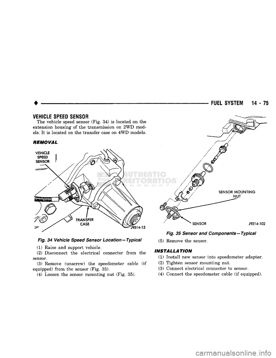
VEHICLE SPEED SENSOR
The vehicle speed sensor (Fig. 34) is located on the
extension housing of the transmission on 2WD mod
els.
It is located on the transfer case on 4WD models.
REMOVAL Fig. 34 Vehicle Speed Sensor Location—Typical
(1) Raise and support vehicle.
(2) Disconnect the electrical connector from the
sensor. (3) Remove (unscrew) the speedometer cable (if
equipped) from the sensor (Fig. 35). (4) Loosen the sensor mounting nut (Fig. 35). Fig. 35 Sensor and Components—Typical
(5) Remove the sensor.
INSTALLATION
(1) Install new sensor into speedometer adapter.
(2) Tighten sensor mounting nut.
(3) Connect electrical connector to sensor.
(4) Connect the speedometer cable (if equipped).
Page 899 of 1502
14 - 80
FUEL SYSTEM
•
SCI
RECEIVE-PCM
INPUT
The serial communication interface (SCI) receive
and transmit outputs allow the PCM to communicate
with the DRB II scan tool.
SENSOR
RETURN-PCM
INPUT
Sensor return provides a low noise ground refer
ence for all system sensors.
SIGNAL
GROUND-PCM
INPUT
Provides a common ground for the input signals.
SPEED
CONTROL-PCM
INPUT
The PCM regulates the speed control system based
on inputs it receives. The speed control operating
range is from 35 to 85 mph. Inputs that effect speed control operation are:
• Park/neutral switch
• Vehicle speed sensor
• Throttle position sensor
• Engine speed sensor
• Brake switch
THROTTLE
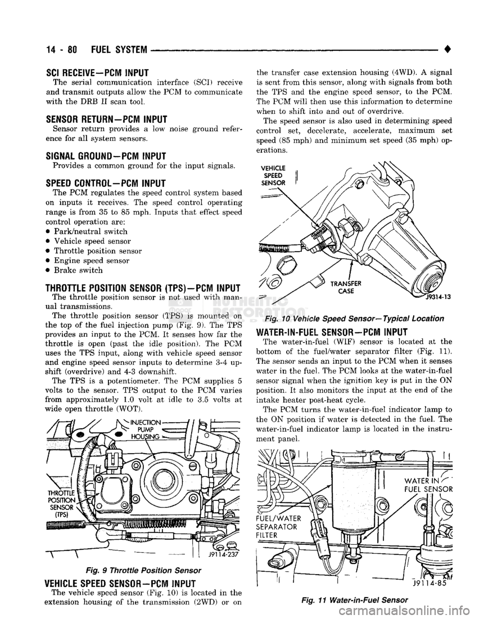
POSITION SENSOR (TPS) —PCM
INPUT
The throttle position sensor is not used with man
ual transmissions. The throttle position sensor (TPS) is mounted on
the top of the fuel injection pump (Fig. 9). The TPS
provides an input to the PCM. It senses how far the
throttle is open (past the idle position). The PCM uses the TPS input, along with vehicle speed sensor and engine speed sensor inputs to determine 3-4 up
shift (overdrive) and 4-3 downshift. The TPS is a potentiometer. The PCM supplies 5
volts to the sensor. TPS output to the PCM varies
from approximately 1.0 volt at idle to 3.5 volts at
wide open throttle (WOT). T
J9114-237
Fig.
9
Throttle
Position
Sensor
VEHICLE SPEED SENSOR-PCM
INPUT
The vehicle speed sensor (Fig. 10) is located in the
extension housing of the transmission (2WD) or on the transfer case extension housing (4WD). A signal
is sent from this sensor, along with signals from both
the TPS and the engine speed sensor, to the PCM.
The PCM will then use this information to determine
when to shift into and out of overdrive.
The speed sensor is also used in determining speed
control set, decelerate, accelerate, maximum set
speed (85 mph) and minimum set speed (35 mph) op
erations.
VEHICLE
SPEED
SENSOR
Fig.
10 Vehicle
Speed
Sensor—Typical Location
WATER-IN-FUEL SENSOR-PCM
INPUT
The water-in-fuel (WIF) sensor is located at the
bottom of the fuel/water separator filter (Fig. 11). The sensor sends an input to the PCM when it senses
water in the fuel. The PCM looks at the water-in-fuel sensor signal when the ignition key is put in the ON
position. It also monitors the input at the end of the intake heater post-heat cycle. The PCM turns the water-in-fuel indicator lamp to
the ON position if water is detected in the fuel. The
water-in-fuel indicator lamp is located in the instru ment panel.
J91 14-85
Fig.
11 Water-in-Fuel
Sensor
Page 946 of 1502
PROPELLER
SHAFTS
16-1
PROPELLER
SHAFTS
CONTENTS
page
GENERAL
INFORMATION
1
TORQUE SPECIFICATIONS
PROPELLER
SHAFT REPLACEMENT
8
UNIVERSAL
JOINT
REPLACEMENT
SERVICE
DIAGNOSIS/PROCEDURES
3
page
15
10
GENERAL INFORMATION
PROPELLER
SHAFTS
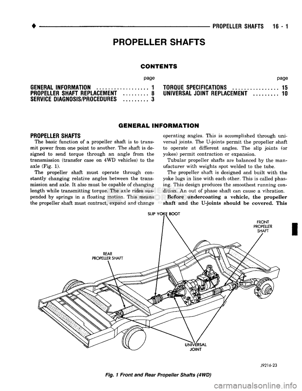
The basic function of a propeller shaft is to trans
mit power from one point to another. The shaft is de
signed to send torque through an angle from the
transmission (transfer case on 4WD vehicles) to the axle (Fig. 1). The propeller shaft must operate through con
stantly changing relative angles between the trans
mission and axle. It also must be capable of changing length while transmitting torque. The axle rides sus
pended by springs in a floating motion. This means
the propeller shaft must contract, expand and change operating angles. This is accomplished through uni
versal joints. The U-joints permit the propeller shaft
to operate at different angles. The slip joints (or
yokes) permit contraction or expansion.
Tubular propeller shafts are balanced by the man
ufacturer with weights spot welded to the tube.
The propeller shaft is designed and built with the
yoke lugs in line with each other. This is called phas ing. This design produces the smoothest running con
dition. An out of phase shaft can cause a vibration.
Before undercoating a vehicle, the propeller
shaft and the U-joints should be covered. This
SLIP
YOKE
BOOT
FRONT
PROPELLER SHAFT
REAR
PROPELLER SHAFT
Fig.
1 Front and Rear Propeller Shafts (4
WD)
J9216-23
Page 950 of 1502
•
PROPELLER
SHAFTS
16-5 A propeller shaft is properly phased when the yoke
ends are on the same plane or in line. A twisted
shaft will throw the yokes out of phase and cause a
noticeable vibration.
When taking universal joint angle measurements
or checking phasing with two piece shafts, consider
each shaft separately. On 4WD vehicles, the front shaft input (pinion shaft) angle has priority over the
caster angle.
Ideally the driveline system should have:
•
Angles that are in equal or opposite within 1
degree of each other
•
Have a 3 degree maximum operating angle
•
Have at least a 1/2 degree continuous operat
ing (propeller shaft) angle Engine speed (R.P.M.) is the main factor though in
determining maximum allowable operating angles.
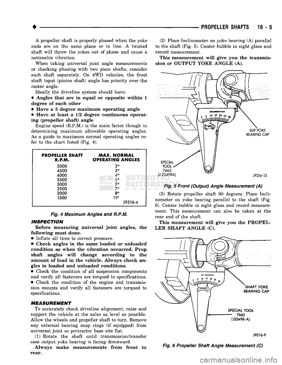
As a guide to maximum normal operating angles re
fer to the chart listed (Fig. 4).
PROPELLER
SHAFT
MAX*
NORMAL
R«P*JVi*
OPERATING
ANGLES
5000
3°
4500
3°
4000
4°
3500
5°
3000
5°
2500
7°
2000
8°
1500 11°
J9316-4
Fig.
4 Maximum
Angles
and
R.P.M.
INSPECTION
Before measuring universal joint angles, the
following must done.
•
Inflate all tires to correct pressure.
•
Check angles in the same loaded or unloaded condition as when the vibration occurred. Prop
shaft angles will change according to the
amount of load in the vehicle. Always check an
gles in loaded and unloaded conditions.
•
Check the condition of all suspension components
and verify all fasteners are torqued to specifications.
•
Check the condition of the engine and transmis
sion mounts and verify all fasteners are torqued to
specifications.
MEASUREMENT
To accurately check driveline alignment, raise and
support the vehicle at the axles as level as possible.
Allow the wheels and propeller shaft to turn. Remove any external bearing snap rings (if equipped) from
universal joint so protractor base sits flat.
(1) Rotate the shaft until transmission/transfer
case output yoke bearing is facing downward.
Always make measurements from front to
rear. (2) Place Inclinometer on yoke bearing (A) parallel
to the shaft (Fig. 5). Center bubble in sight glass and
record measurement.
This measurement will give you the transmis
sion or OUTPUT YOKE ANGLE (A).
Fig.
5 Front (Output)
Angle
Measurement (A)
(3) Rotate propeller shaft 90 degrees. Place Incli
nometer on yoke bearing parallel to the shaft (Fig.
6).
Center bubble in sight glass and record measure
ment. This measurement can also be taken at the
rear end of the shaft.
This measurement will give you the PROPEL
LER SHAFT ANGLE (C). J9216-9
Fig.
6 Propeller Shaft
Angle
Measurement (C)