oil filter DODGE TRUCK 1993 Service Workshop Manual
[x] Cancel search | Manufacturer: DODGE, Model Year: 1993, Model line: TRUCK, Model: DODGE TRUCK 1993Pages: 1502, PDF Size: 80.97 MB
Page 1092 of 1502
AUTOMATIC
TRANSMISSION—32RH/36RH/37RH/42RH/46RH
21 - 91
TEST
CONDITION
Line pressure OK during
any one test
Line Pressure OK in
R
but low in D, 2, 1
Pressure Low in D
Fourth Gear Range
Pressure OK in 1, 2 but
low
in
D3
and
R
Pressure OK in 2 but low in
R
and 1
Front servo pressure low
in 2
Pressure low in all positions
Governor pressure too high
at idle speed
Governor pressure low
at all mph figures Lubrication pressure low at
all throttle positions
INDICATION
Pump and regulator valve OK
Leakage in rear clutch area (servo,
clutch seals, governor support seal rings)
Overdrive clutch piston seal, or
check ball problem
Leakage in front clutch area (servo,
clutch seals, retainer bore, pump seal rings)
Leakage in rear servo
Leakage in servo; broken servo
ring or cracked servo piston
Clogged filter, stuck regulator
valve, worn or faulty pump, plugged fluid cooler
Governor valve sticking open
Governor valve sticking closed
Clogged oil cooler or lines, seal rings leaking, output shaft plugged
with debris, worn bushings in pump or clutch retainer
J9321-165
Fig.
7
Pressure
Test
Analysis
Chart (42RH/46RH)
STALL
TEST
DIAGNOSIS
Stall
Speed
Too
High
If stall speed exceeds specifications by more than
200 rpm, transmission clutch slippage is indicated.
Stall
Speed
Too Low Low stall speeds with a properly tuned engine in
dicate a torque converter overrunning clutch prob
lem. The condition should be confirmed by road
testing prior to converter replacement. The converter overrunning clutch is slipping when:
Stall speeds are 250 to 350 rpm below specified min
imum and the vehicle operates properly at highway
speeds but has poor low speed acceleration.
Stall
Speed
Normal
If stall speeds are normal but abnormal throttle
opening is required to maintain highway speeds, the
converter overrunning clutch is seized and the torque
converter must be replaced.
Converter
Noise
During
Test
A whining noise caused by fluid flow is normal
during a stall test. However, loud metallic noises in dicate a damaged converter. To confirm that noise is
originating from the converter, operate the vehicle at
light throttle in Drive and Neutral on a hoist and
lis
ten for noise coming from the converter housing.
AIR
TESTING
CLUTCH
AND
BAND
OPERATION
Air pressure testing can be used to check clutch
and band operation with the transmission either in
the vehicle, or on the work bench as a final check af
ter overhaul. Air pressure testing requires that the oil pan and
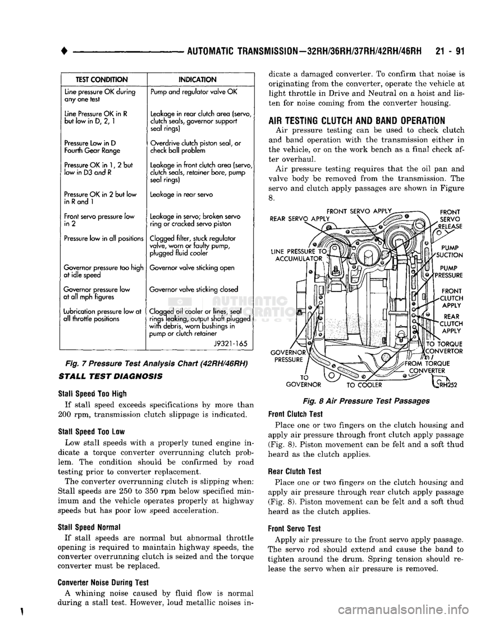
valve body be removed from the transmission. The servo and clutch apply passages are shown in Figure
8.
FRONT
SERVO
APPLY^
REAR
SERVO
APPLY
LINE
PRESSURE
TO
ACCUMULATOR
GOVERNOR
PRESSURE
FRONT
SERVO
RELEASE
PUMP
SUCTION
PUMP
PRESSURE
FRONT
CLUTCH
APPLY
REAR
CLUTCH
APPLY
TO
TORQUE
CONVERTOR
I
FROM
TORQUE
CONVERTER
TO
GOVERNOR
TO
COOLER
^H252
Fig.
8 Air
Pressure
Test
Passages
Front
Clutch
Test
Place one or two fingers on the clutch housing and
apply air pressure through front clutch apply passage (Fig. 8). Piston movement can be felt and a soft thud
heard as the clutch applies.
Rear
Clutch
Test
Place one or two fingers on the clutch housing and
apply air pressure through rear clutch apply passage
(Fig. 8). Piston movement can be felt and a soft thud
heard as the clutch applies.
Front
Servo
Test
Apply air pressure to the front servo apply passage.
The servo rod should extend and cause the band to
tighten around the drum. Spring tension should re lease the servo when air pressure is removed.
Page 1097 of 1502
21 - 96
AUTOMATIC
TRANSMISSION—32RH/36RH/37RH/42RH/46RH
• Condition
Possible
Cause
Correction
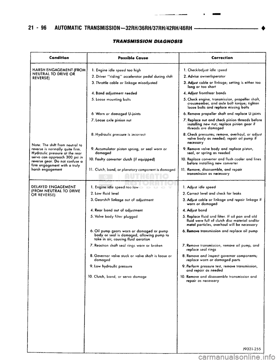
HARSH
ENGAGEMENT
(FROM
NEUTRAL
TO
DRIVE
OR
REVERSE)
Note: The shift from
neutral
to
reverse is normally
quite
firm. Hydraulic pressure at the
rear
servo can approach 300 psi in
reverse gear. Do not confuse a
firm
engagement
with
a
truly
harsh engagement
1.
Engine
idle
speed too high
2. Driver "riding" accelerator pedal during shift
3.
Throttle
cable or linkage misadjusted
4. Band adjustment needed
5.
Loose
mounting bolts
6 Worn or damaged
U-joints
7.
Loose
axle
pinion nut
8. Hydraulic pressure is incorrect
9. Accumulator piston spring, or seal worn or damaged
10. Faulty converter clutch (if equipped)
11.
Clutch, band, or
planetary
component
is
damaged 1. Check/adjust
idle
speed
2. Advise owner/operator
3. Adjust cable or linkage; setting is
either
too long or too short
4. Adjust
front/rear
bands
5. Check engine, transmission,
propeller
shaft, crossmember, and
axle
bolt torque;
tighten
loose
bolts and replace
missing
bolts
6. Remove
propeller
shaft and replace
U-joints
7. Replace nut and check pinion threads
before
installing new nut; replace pinion gear if
threads are damaged
8. Check pressures; remove, overhaul, or adjust valve body as needed;
repair
oil pump if
necessary
9. Remove valve body and replace piston,
seal,
or spring as needed
10. Replace converter and flush cooler and lines
before
installing new converter
11.
Remove, disassemble, and
repair
transmission
as necessary
DELAYED
ENGAGEMENT
(FROM
NEUTRAL
TO
DRIVE
OR
REVERSE)
1.
Engine
idle
speed too low
2. Low
fluid
level
3. Gearshift linkage but of adjustment
4. Rear band out of adjustment
5.
Valve body
filter
plugged
6. Oil pump gears worn or damaged or pump body or seal is damaged, allowing pump to
take
in air, causing
fluid
aeration
7. Reaction shaft seal rings worn or broken
8. Governor valve stuck or valve shaft is loose or damaged
9. Low hydraulic pressure
10. Clutch, band, or servo damage
1.
Adjust
idle
speed
2. Correct
level
and check for leaks
3. Adjust cable or linkage and
repair
linkage if worn or damaged
4. Adjust band
5. Replace
fluid
and
filter.
If oil pan and old
fluid
were
full
of clutch
disc
material
and/or
metal
particles, overhaul
will
be necessary
6. Remove transmission and replace oil pump
7. Remove transmission, remove oil pump, and replace seal rings
8. Remove and inspect governor components; replace worn or damaged parts
9. Perform pressure test, remove transmission, and
repair
as needed
10. Remove and disassemble transmission and
repair
as necessary
J9321-255
TRANSMISSION DIAGNOSIS
Page 1098 of 1502
•
AUTOMATIC
TRANSMISSION—32RH/36RH/37RH/42RH/46RH
21 - 97
Cenoltfeie
Possible
Caws®
Cowscilon
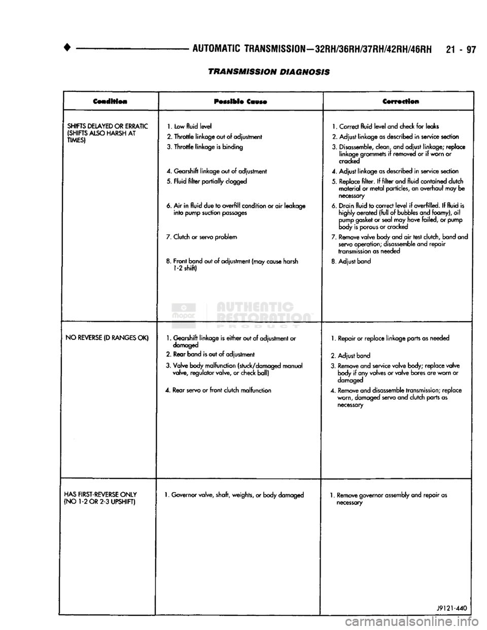
SHIFTS
DELAYED
OR
ERRATIC
(SHIFTS
ALSO
HARSH
AT
TIMES)
1.
Low
fluid
level
2.
Throttle
linkage out
of
adjustment
3.
Throttle
linkage
is
binding
4.
Gearshift linkage out
of
adjustment
5. Fluid
filter
partially
clogged
6. Air in
fluid
due to
overfill
condition or
air
leakage
into
pump suction
passages
7.
Clutch
or
servo problem
8. Front band out of adjustment (may
cause
harsh
1-2
shift)
1.
Correct
fluid
level
and check
for
leaks
2. Adjust linkage
as
described in service section
3.
Disassemble,
clean, and adjust linkage; replace linkage grommets
if
removed
or if
worn or
cracked
4.
Adjust linkage
as
described in service section
5. Replace
filter. If filter
and
fluid
contained clutch
material
or
metal
particles, an overhaul may
be
necessary
6. Drain
fluid
to correct
level
if
overfilled.
If
fluid
is
highly
aerated
(full
of
bubbles
and foamy),
oil
pump
gasket
or seal may have failed,
or
pump
body
is
porous
or cracked
7.
Remove valve body and
air
test clutch, band and
servo
operation;
disassemble
and
repair
transmission
as needed
8. Adjust band
NO
REVERSE
(D
RANGES
OK)
1.
Gearshift linkage is
either
out of adjustment or
damaged
2. Rear band
is
out
of
adjustment
3. Valve body malfunction (stuck/damaged manual valve, regulator valve,
or
check ball)
4.
Rear servo or
front
clutch malfunction
1.
Repair or replace linkage parts as needed
2. Adjust band
3. Remove and service valve body; replace valve body
if
any valves or valve bores are worn
or
damaged
4.
Remove and
disassemble
transmission;
replace worn, damaged servo and clutch parts as
necessary
HAS
FIRST-REVERSE
ONLY
(NO
1-2
OR
2-3
UPSHIFT)
1.
Governor valve, shaft, weights, or body damaged
1.
Remove governor
assembly
and
repair
as
necessary
J9121-440
TRANSMISSION DIAGNOSIS
Page 1103 of 1502
21-102
AUTOMATIC
TRANSMISSION—32RH/36RH/37RH/42RH/46RH
TRANSMISSION
DIAGNOSIS
•
Condition
Possible
Cause Correction
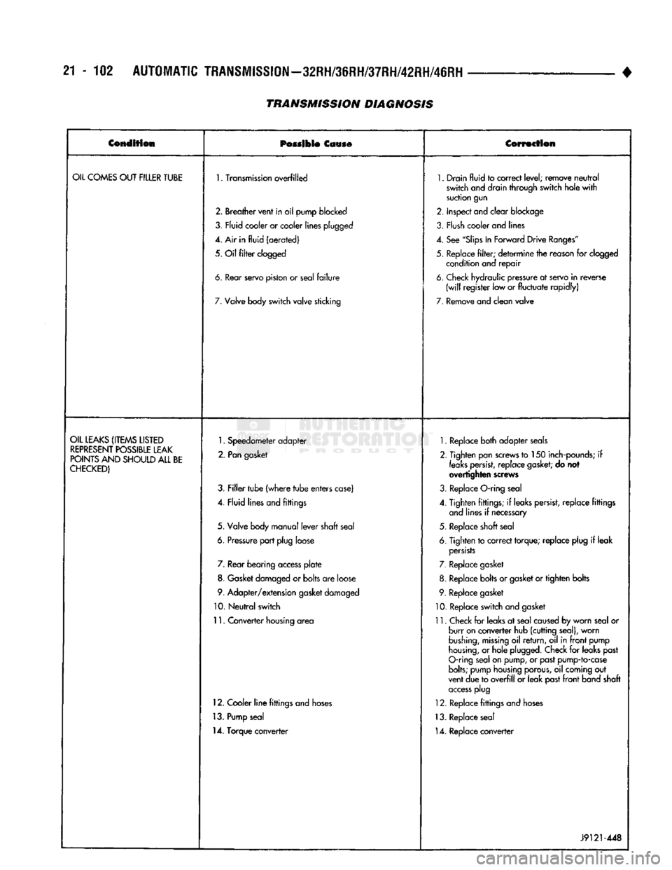
OIL
COMES
OUT
FILLER
TUBE
1.
Transmission
overfilled
1.
Drain
fluid
to
correct
level;
remove
neutral
switch
and drain
through
switch
hole
with
suction
gun
2.
Breather
vent
in
oil
pump
blocked
2.
Inspect
and
clear
blockage
3,
Fly id
cooler
or cooler
lines
plugged
3.
Flush
cooler and lines
4. Air in
fluid
(aerated)
4.
See
"Slips
In
Forward
Drive
Ranges"
5.
Oil
filter
clogged
5.
Replace
filter;
determine
the reason for clogged
condition and
repair
6.
tear
servo
piston
or
seal
failure
6.
Check hydraulic pressure at servo
in
reverse
(will
register
low or
fluctuate
rapidly)
7.
Valve body
switch
valve
sticking
7.
Remove
and
clean
valve
OIL
LEAKS
(ITEMS
LISTED
REPRESENT
POSSIBLE
LEAK
POINTS
AND
SHOULD
ALL
BE
CHECKED)
1.
Speedometer
adapter
2.
Pan
gasket
3.
Filler
tube
(where
tube
enters
case)
4.
Fluid
lines
and
fittings
5.
Valve body
manual
lever
shaft
seal
6.
Pressure
port
plug
loose 7. Rear
bearing
access
plate
8. Gasket damaged or
bolts
are loose
9.
Adapter/extension
gasket damaged
10.
Neutral
switch
11.
Converter
housing area
12. Cooler
line
fittings and hoses
13. Pump seal
14. Torque converter
1.
Replace both adapter seals
2. Tighten pan screws to 150 inch-pounds; if
leaks
persist,
replace
gasket;
do not
overtighten screws
3. Replace O-ring seal
4. Tighten fittings; if leaks persist, replace fittings and lines if necessary
5. Replace shaft seal
6. Tighten to correct torque; replace plug if leak
persists
7. Replace gasket
8. Replace bolts or gasket or tighten bolts
9. Replace gasket
10. Replace switch and gasket
11. Check for leaks at seal caused by worn seal or burr on converter hub (cutting seal), worn
bushing,
missing
oil
return,
oil in
front
pump
housing,
or hole plugged. Check for leaks past
O-ring seal on pump, or past pump-to-case
bolts;
pump housing porous, oil coming out
vent due to
overfill
or leak past
front
band shaft
access
plug
12. Replace fittings and hoses
13. Replace seal 14. Replace converter
J9121-448
Page 1104 of 1502
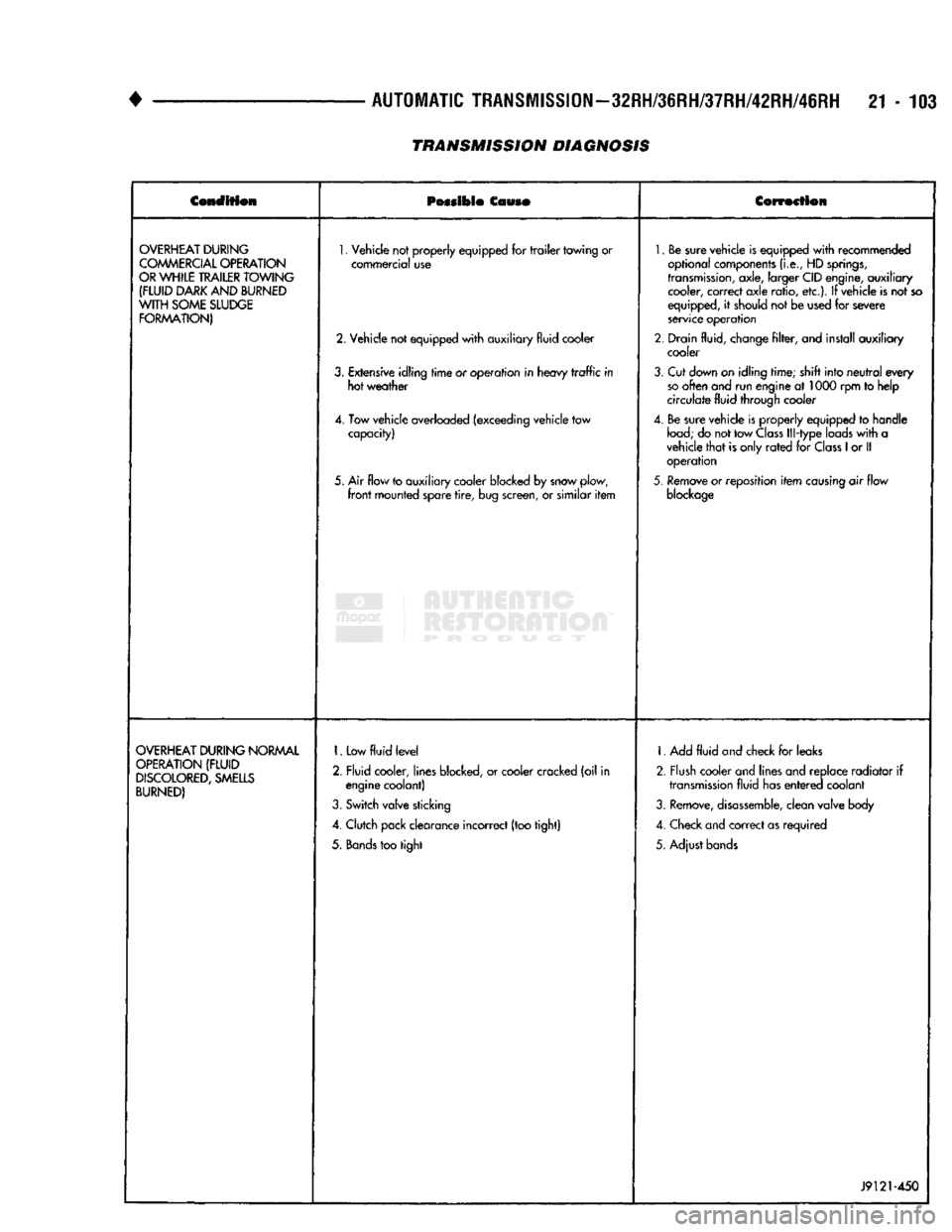
•
AUTOMATIC
TRANSMISSION—32RH/36RH/37RH/42RH/46RH
21-103
TRANSMISSION DIAGNOSIS
Condition
Possible
Couso
Correction
OVERHEAT
DURING
COMMERCIAL
OPERATION
OR
WHILE
TRAILER
TOWING
(FLUID
DARK
AND
BURNED
WITH
SOME
SLUDGE
FORMATION)
1.
Vehicle not properly equipped for
trailer
towing or
commercial use
2. Vehicle not equipped
with
auxiliary fluid cooler
3.
Extensive idling
time
or operation in heavy
traffic
in hot weather
4. Tow vehicle overloaded (exceeding vehicle tow capacity)
5. Air flow to auxiliary cooler blocked by snow plow,
front
mounted spare
tire,
bug screen, or similar
item
1.
Be sure vehicle is equipped
with
recommended
optional components
(i.e.,
HD
springs,
transmission,
axle, larger CID engine, auxiliary cooler, correct axle ratio, etc.). If vehicle is not so
equipped, it should not be used for severe
service operation
2. Drain fluid, change
filter,
and install auxiliary cooler
3.
Cut down on idling time; shift into
neutral
every
so
often and run engine at 1000 rpm to help
circulate fluid through cooler
4. Be sure vehicle is properly equipped to handle
load;
do not tow
Class
Ill-type loads
with
a
vehicle
that
is only
rated
for
Class
1
or II operation
5.
Remove or reposition
item
causing
air flow
blockage
OVERHEAT
DURING
NORMAL
OPERATION
(FLUID
DISCOLORED,
SMELLS
BURNED)
1.
Low
fluid
level
2. Fluid cooler, lines blocked, or cooler cracked (oil in engine coolant)
3.
Switch valve sticking
4. Clutch pack clearance incorrect (too tight)
5.
Bands
too tight 1. Add
fluid
and check for leaks
2. Flush cooler and lines and replace radiator if
transmission
fluid has
entered
coolant
3.
Remove,
disassemble,
clean valve body
4. Check and correct as required
5. Adjust bands
J9121-450
Page 1114 of 1502
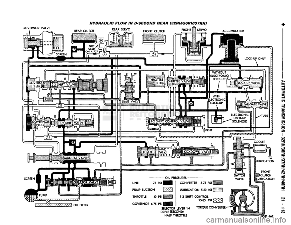
GOVERNOR VALVE
HYDRAULIC FLOW IN DSEGOND GEAR (32RH/36RH/37RH)
FRONT
M
SERVO REAR SERVO
FRONT
CLUTCH
ACCUMULATOR
3 OIL
FILTER
LINE
75
PSI
PUMP
SUCTION
\y>>>
THROTTLE
40
PSI
WMM
GOVERNOR
6-75 PSI
CONVERTER
5-75
PSI
LUBRICATION
5-30
PSI
WMM (j
1-2
SHIFT CONTROL
M
25-35
PSI
^ (i
SELECTOR
LEVER
IN
TORQUE CONVERTER-**!
DRIVE
(SECOND)
(|
HALF THROTTLE TO
LUBRICATION
FRONT
^CLUTCH
LUBRICATION
J9021-162
Page 1119 of 1502
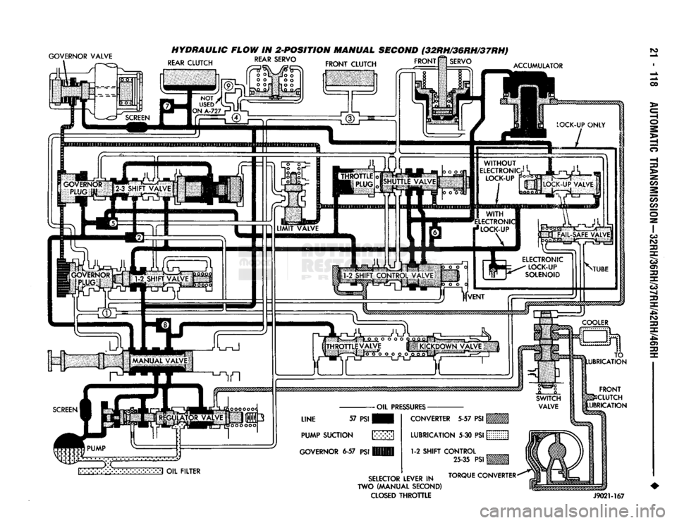
GOVERNOR
VALVE
HYDRAULIC
FLOW IN 2-POSITION MANUAL
SECOND
(32RH/36RH/37RH)
ro
REAR
CLUTCH
REAR
SERVO
FRONT CLUTCH FRONT
SERVO
ACCUMULATOR
l/M-lvX'Xv:-:--I
OIL FILTER FRONT
CLUTCH
UBRICATION
SELECTOR
LEVER IN TORQUE CONVERTER*
TWO (MANUAL SECOND)
IBU^wSSS^^^i
CLOSED
THROTTLE
J9021-167
O
O
ao
>
oo
00
m
rO
30
c3
o> 30
30
3^ ro
30
30 r
Page 1131 of 1502
21
-
130
IN-VEHICLE
SERVICE-~32RH/36RH/37RH/42RH/4iRH
•
IN-VEHICLE
SERVICE-32RH/36RH/37RH/42RH/46RH
INDEX
page
Aluminum Thread Repair
141
Checking
Fluid
Level
130
Extension Housing Bushing
and
Output
Shaft
Bearing
Service-32RH/36RH/37RH
... .
135
Extension Housing Yoke Seal Replacement
....
135
Fluid
and Filter
Change
130
Front
Band
Adjustment
133
Gearshift Linkage
Adjustment
130
Governor
and
Park Gear Service—
32RH/36RH/37RH
137
Governor
and
Park Lock Service—42RH/46RH
.
138
CHECKING
FLUID LEVEL
(1) Position vehicle
on
level surface. This
is ex
tremely important
for
accurate check.
(2)
Apply parking brakes
and run
engine
at
curb
idle speed.
(3)
Shift transmission momentarily into
all
gear
ranges. Then shift back
to
Neutral.
(4)
Clean
top of
filler tube
and
dipstick
(to
avoid
dirt entry)
and
check fluid level. Correct level
is as
follows:
(5)
Be
sure fluid
is at
normal operating tempera
ture (180°F). Correct level
is
between "Maximum Level
Hot"
and
"Add"
marks (crosshatched area)
on
dipstick. (6)
If
fluid level
is
low,
add
only enough fluid
to
correct level.
CAUTION:
Do not
overfill
the
transmission. Overfilling
will
force fluid
out
the
pump vent which
can
be
mistaken
for
a
pump seal leak. Overfilling
will
also
cause
fluid aeration
and foaming
when
the
excess
fluid
is
picked
up
and
churned
by
the
gear train. Aeration
will
reduce fluid
life
significantly.
FLUID
AND
FILTER
CHANGE
Normal Change
Interval
The fluid
and
filter should
be
changed
(and the
bands adjusted)
at
recommended maintenance inter
vals.
Or
whenever
the
transmission
has
been disassembled
for
any
reason.
Recommended Fluid
The recommended
(and
preferred) fluid
for
Chrysler automatic transmissions
is
Mopar
ATF
Plus,
type
7176.
Use
Mopar Dexron
II
only when
ATF Plus
is not
readily available.
page
Park Lock
Service-32RH/36RH/37RH
. 138
Park/Neutral Position Switch
134
Rear
Band
Adjustment
133
Speedometer Service
134
Transmission Cooler Service
140
Transmission
Throttle
Cable
Adjustment-
Cummins Diesel Engine
132
Transmission
Throttle
Cable
Adjustment-
Gas
Engines
131
Valve Body
Control
Pressure Adjustments
.....
140
Valve Body Service
138
Severe Usage Change
Interval
Under severe usage,
the
fluid
and
filter should
be
changed
and the
bands adjusted
at
12,000 mile (19,000
km)
intervals.
Severe usage
is
defined
as:
• More than half
of
vehicle operation occurs
in
heavy city traffic during
hot
weather
at
ambient
temperatures above
90°
F.
• Vehicle
is
used
for
Taxi, Police, Limousine,
or
sim
ilar commercial operations.
• Vehicle
is
used
for
trailer/boat towing
or
heavy
load hauling. When
the
factory fluid
is
drained, refill
the
trans
mission with Mopar
ATF
Plus, type
7176
fluid.
Mo
par Dexron
II
can
be
used
if
ATF
Plus
is
not
readily available.
FLUID
AND
FILTER
REPLACEMENT
PROCEDURE
(1) Raise vehicle, remove
oil pan
and
drain fluid.
(2) Remove filter screws
and
remove filter.
(3) Position
new
filter
on
valve body
and
install fil
ter screws finger tight. (4) Tighten filter screws
to 4
N*m (35
in.
lbs.)
with
torque wrench.
(5) Position
new
gasket
on oil pan
and
install
pan
on transmission. Tighten
pan
bolts
to 17
N»m
(150
in.
lbs.)
torque. (6) Lower vehicle
and
refill transmission with rec
ommended fluid.
GEARSHIFT LINKAGE ADJUSTMENT
Check linkage adjustment
by
starting
the
engine
in Park
and
Neutral. Adjustment
is
OK
if
the
engine starts only
in
park
and Neutral. Adjustment
is
incorrect
if
the
engine starts
in one
but
not
both positions. If
the
engine starts
in
any
position other than Park
or Neutral,
or if
the
engine will
not
start
at
all,
the
park/neutral position switch
may
be
faulty.
Page 1139 of 1502
21
- 138
IN-VEHICLE SERVSCE-32RH/36RH/37RH/42RH/46RH
(2) Install and tighten gear-to-body bolts finger
tight. Make sure oil passage in governor body aligns
with matching passage in gear. (3) Install assembled governor body and gear on
output shaft.
(4) Position governor body so valve shaft hole in
body aligns with matching hole in output shaft. Then slide body and park gear into place. (5) Install snap ring securing governor and park
gear to output shaft (Fig. 22).
(6) Tighten bolts attaching governor body to park
gear to 11 N»m (95 in. lbs.) torque.
(7) Assemble governor weights and spring. Secure
inner weight and spring in outer weight with snap
ring (Fig. 21).
(8) Install weight assembly in governor body and
install retaining snap ring (Fig. 21).
(9) Place governor valve on valve shaft. Insert shaft
in governor body, through governor weights and output
shaft. Be sure valve is properly seated in body.
(10) Secure valve shaft with small snap ring.
(11) Install output shaft bearing and extension
housing. Refer to procedure in this section.
GOVERNOR
AND
PARK LOCK SERVICE—42RH/
46RH
The governor and park lock components are located
within the overdrive unit and cannot be serviced in
the vehicle. The overdrive unit must be removed and disassem
bled for access to the governor and park lock compo
nents.
Refer to the 42RH/46RH overdrive unit service sec
tions for repair procedures.
PARK
LOCK SERVICE—32RH/36RH/37RH
PARK LOCK
COMPONENT REMOVAL
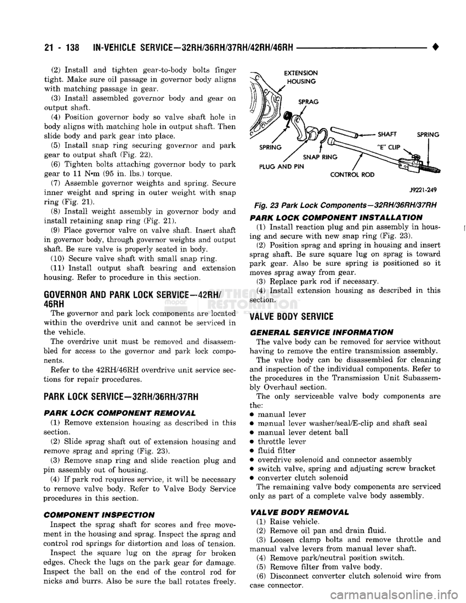
(1) Remove extension housing as described in this
section. (2) Slide sprag shaft out of extension housing and
remove sprag and spring (Fig. 23).
(3) Remove snap ring and slide reaction plug and
pin assembly out of housing. (4) If park rod requires service, it will be necessary
to remove valve body. Refer to Valve Body Service
procedures in this section.
COMPONENT INSPECTION
Inspect the sprag shaft for scores and free move
ment in the housing and sprag. Inspect the sprag and control rod springs for distortion and loss of tension.
Inspect the square lug on the sprag for broken
edges.
Check the lugs on the park gear for damage. Inspect the ball on the end of the control rod for
nicks and burrs. Also be sure the ball rotates freely.
J9221-249
Fig. 23
Park
Lock Components-32RH/36RH/37RH
PARK
LOCK
COMPONENT INSTALLATION
(1) Install reaction plug and pin assembly in hous
ing and secure with new snap ring (Fig. 23).
(2) Position sprag and spring in housing and insert
sprag shaft. Be sure square lug on sprag is toward
park gear. Also be sure spring is positioned so it moves sprag away from gear.
(3) Replace park rod if necessary. (4) Install extension housing as described in this
section.
VALVE BODY
SERVICE
GENERAL SERVICE
INFORMATION
The valve body can be removed for service without
having to remove the entire transmission assembly. The valve body can be disassembled for cleaning
and inspection of the individual components. Refer to
the procedures in the Transmission Unit Subassem
bly Overhaul section.
The only serviceable valve body components are
the:
• manual lever
• manual lever washer/seal/E-clip and shaft seal
• manual lever detent ball
• throttle lever
• fluid filter
• overdrive solenoid and connector assembly
• switch valve, spring and adjusting screw bracket • converter clutch solenoid The remaining valve body components are serviced
only as part of a complete valve body assembly.
VALVE
BODY
REMOVAL
(1) Raise vehicle.
(2) Remove oil pan and drain fluid.
(3) Loosen clamp bolts and remove throttle and
manual valve levers from manual lever shaft. (4) Remove park/neutral position switch. (5) Remove filter from valve body.
(6) Disconnect converter clutch solenoid wire from
case connector.
Page 1140 of 1502
•
IN-VEHICLE
SERVICE-32RH/36RH/37RH/42RH/46RH
21 - 139 (7) Push solenoid connector out of case.
(8) Remove valve body attaching screws.
(9) Lower valve body enough to remove accumula
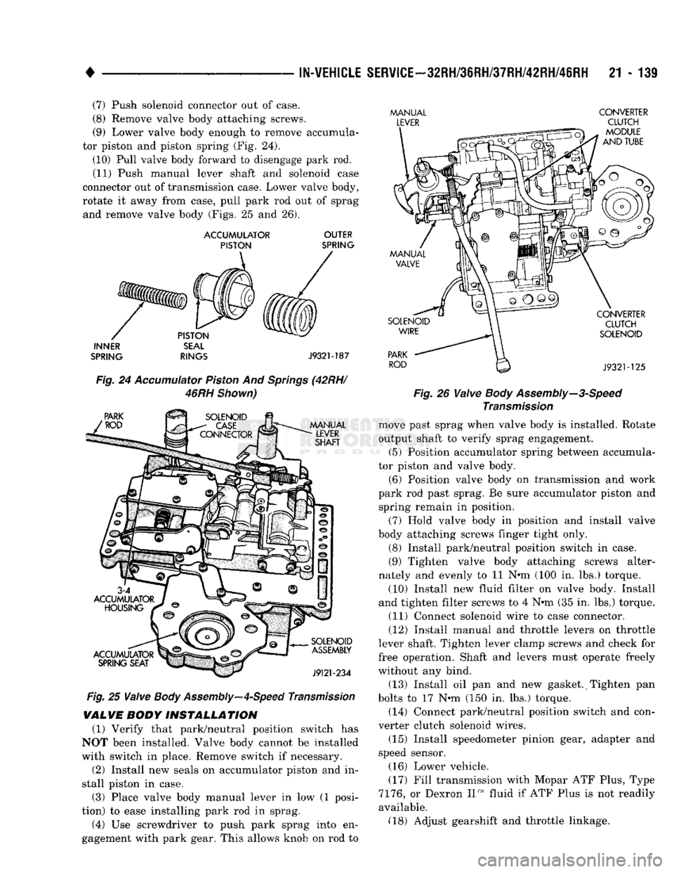
tor piston and piston spring (Fig. 24).
(10) Pull valve body forward to disengage park rod. (11) Push manual lever shaft and solenoid case
connector out of transmission case. Lower valve body,
rotate it away from case, pull park rod out of sprag and remove valve body (Figs. 25 and 26).
ACCUMULATOR
OUTER
PISTON
SPRING
INNER
SEAL
SPRING
RINGS
J932M87
Fig.
24
Accumulator
Piston
And
Springs
(42RH/
46RH
Shown)
Fig.
25
Valve
Body
Assembly—4-Speed
Transmission
VALVE
BODY
INSTALLATION
(1) Verify that park/neutral position switch has
NOT been installed. Valve body cannot be installed
with switch in place. Remove switch if necessary.
(2) Install new seals on accumulator piston and in
stall piston in case.
(3) Place valve body manual lever in low (1 posi
tion) to ease installing park rod in sprag.
(4) Use screwdriver to push park sprag into en
gagement with park gear. This allows knob on rod to
MANUAL
CONVERTER
LEVER
CLUTCH
- Fig. 26
Valve
Body
Assembly—3-Speed
Transmission
move past sprag when valve body is installed. Rotate
output shaft to verify sprag engagement. (5) Position accumulator spring between accumula
tor piston and valve body.
(6) Position valve body on transmission and work
park rod past sprag. Be sure accumulator piston and spring remain in position.
(7) Hold valve body in position and install valve
body attaching screws linger tight only.
(8) Install park/neutral position switch in case.
(9) Tighten valve body attaching screws alter
nately and evenly to 11 N#m (100 in. lbs.) torque.
(10) Install new fluid filter on valve body. Install
and tighten filter screws to 4 N-m (35 in. lbs.) torque. (11) Connect solenoid wire to case connector.
(12) Install manual and throttle levers on throttle
lever shaft. Tighten lever clamp screws and check for
free operation. Shaft and levers must operate freely
without any bind.
(13) Install oil pan and new gasket. (Tighten pan
bolts to 17 N»m (150 in. lbs.) torque. (14) Connect park/neutral position switch and con
verter clutch solenoid wires.
(15) Install speedometer pinion gear, adapter and
speed sensor.
(16) Lower vehicle.
(17) Fill transmission with Mopar ATF Plus, Type
7176,
or Dexron II™ fluid if ATF Plus is not readily
available. (18) Adjust gearshift and throttle linkage.