oil filter DODGE TRUCK 1993 Service Owner's Guide
[x] Cancel search | Manufacturer: DODGE, Model Year: 1993, Model line: TRUCK, Model: DODGE TRUCK 1993Pages: 1502, PDF Size: 80.97 MB
Page 709 of 1502
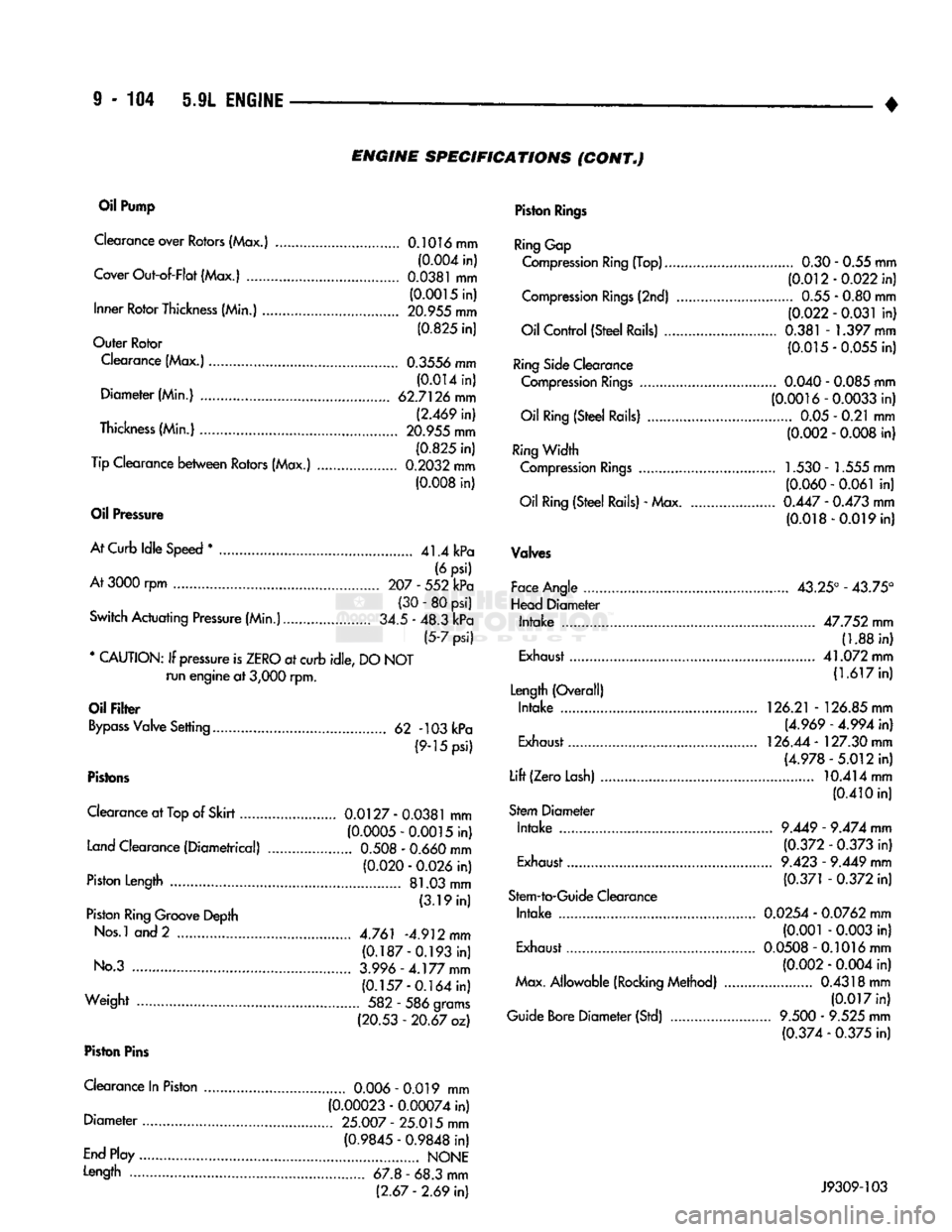
9 - 104 5.9L ENGINE
• ENGINE
SPECIFICATIONS
(CONT„)
Oil
Pump
Clearance over Rotors (Max.) 0.1016 mm (0.004 in)
Cover Out-of-Flat (Max.)
0.0381
mm (0.0015 in)
Inner Rotor Thickness (Min.) 20.955 mm
(0.825 in)
Outer Rotor
Clearance (Max.) 0.3556 mm (0.014 in)
Diameter (Min.) 62.7126 mm (2.469 in)
Thickness (Min.) 20.955 mm (0.825 in)
Tip Clearance between Rotors (Max.) 0.2032 mm (0.008 in)
Oil
Pressure
At Curb Idle Speed
*
41.4 kPa (6 psi)
At
3000 rpm 207 - 552 kPa (30 - 80 psi)
Switch Actuating Pressure (Min.) 34.5 - 48.3 kPa (5-7 psi)
* CAUTION: If pressure is ZERO at curb idle, DO NOT run engine at
3,000
rpm.
Oil
Filter
Bypass Valve Setting 62 -103 kPa (9-15 psi)
Pistons
Clearance at
Top
of Skirt 0.0127
-
0.0381
mm (0.0005-0.0015 in)
Land Clearance (Diametrical)
0.508
-
0.660
mm (0.020 -
0.026
in)
Piston Length 81.03 mm (3.19 in)
Piston Ring Groove Depth
Nos.l and 2 4.761 -4.912 mm (0.187-0.193 in)
No.3 3.996-4.177
mm
(0.157-0.164 in)
Weight 582 - 586 grams (20.53 - 20.67 oz)
Piston
Pins
Clearance In Piston
0.006
- 0.019 mm (0.00023 - 0.00074 in)
Diameter 25.007
-
25.015 mm
(0.9845 - 0.9848 in)
End Play NONE
Length 67.8 - 68.3 mm (2.67
-
2.69 in)
Piston
Rings
Ring Gap
Compression Ring (Top) 0.30 - 0.55 mm (0.012-0.022 in)
Compression Rings (2nd) 0.55 - 0.80 mm (0.022 - 0.031 in)
Oil Control (Steel Rails) 0.381 - 1.397 mm (0.015-0.055 in)
Ring Side Clearance Compression Rings
0.040
-
0.085
mm (0.0016-0.0033 in)
Oil Ring (Steel Rails) 0.05 - 0.21 mm (0.002 -
0.008
in)
Ring Width Compression Rings 1.530 - 1.555 mm (0.060 - 0.061 in)
Oil Ring (Steel Rails) - Max
0.447
-
0.473
mm (0.018-0.019 in)
Valves
Face Angle 43.25° - 43.75°
Head Diameter Intake 47.752 mm (1.88 in)
Exhaust 41.072 mm
(1.617 in)
Length (Overall) Intake 126.21 - 126.85 mm
(4.969 - 4.994 in)
Exhaust 126.44 - 127.30 mm
(4.978-5.012 in)
Lift (Zero Lash) 10.414 mm
(0.410 in)
Stem Diameter Intake
9.449
-
9.474
mm
(0.372 -
0.373
in)
Exhaust
9.423
-
9.449
mm
(0.371 -
0.372
in)
Stem-to-Guide Clearance Intake 0.0254 - 0.0762 mm (0.001 -
0.003
in)
Exhaust 0.0508-0.1016 mm
(0.002 -
0.004
in)
Max. Allowable (Rocking Method) 0.4318 mm (0.017 in)
Guide Bore Diameter (Std)
9.500
-
9.525
mm (0.374 -
0.375
in) J9309-103
Page 712 of 1502
•
5.9L
(DIESEL)
ENGINE
9 -
107
5.9L
(DIESEL)
ENGINE
SERVICE
PROCEDURES
INDEX
page
Camshaft
127
Crankshaft
138
Cylinder
Block
129
Cylinder
Head
113
Engine
Assembly
. 109
Engine
Front
Mounts
(Insulators
/
Brackets)
... 107
Engine
Rear Support
108
Gear
Housing
/
Cover
122
General
Information
107
Oil Cooler Element
/
Gasket
. 149
Oil
Filter
148
page
Oil
Filter
Bypass
Valve
. 148
Oil Pan
/
Suction Tube
146
Oil Pressure Regulator Valve
/
Spring
148
Oil Pump
146
Piston
/
Connecting
Rod
Assembly
134
Rocker
Levers
/
Push
Rods
112
Specifications—5.9L Diesel Engines
151
Tappet
125
Timing
Pin
123
Valve Clearance
Adjustment
...............
121
Valves
and
Valve Springs
116
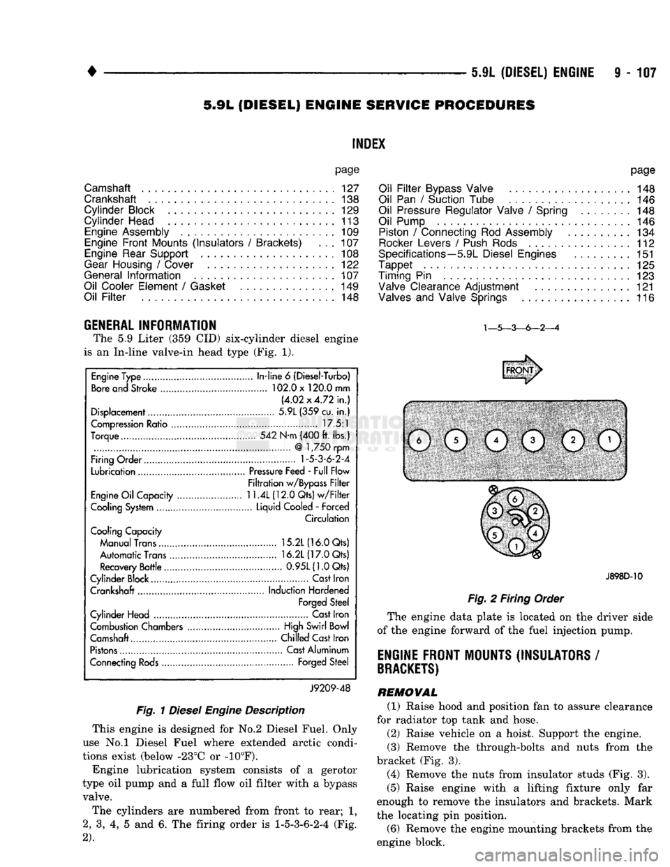
GENERAL INFORMATION The
5.9
Liter
(359 CID)
six-cylinder diesel engine
is
an
In-line valve-in head type
(Fig. 1).
Fig.
1
Diesel
Engine
Description
This engine
is
designed
for No.2
Diesel Fuel. Only
use
No.l
Diesel Fuel where extended arctic condi
tions exist (below -23°C
or -10°F).
Engine lubrication system consists
of a
gerotor
type
oil
pump
and a
full flow
oil
filter with
a
bypass valve.
The cylinders
are
numbered from front
to
rear;
1,
2,
3, 4, 5 and 6. The
firing order
is
1-5-3-6-2-4
(Fig.
2).
J898D-10
Fig.
2
Firing Order
The engine data plate
is
located
on the
driver side
of
the
engine forward
of the
fuel injection pump.
ENGINE FRONT MOUNTS (INSULATORS
/
BRACKETS)
REMOVAL (1) Raise hood
and
position
fan to
assure clearance
for radiator
top
tank
and
hose.
(2) Raise vehicle
on a
hoist. Support
the
engine.
(3) Remove
the
through-bolts
and
nuts from
the
bracket
(Fig. 3).
(4) Remove
the
nuts from insulator studs
(Fig. 3).
(5) Raise engine with
a
lifting fixture only
far
enough
to
remove
the
insulators
and
brackets. Mark
the locating
pin
position.
(6) Remove
the
engine mounting brackets from
the
engine block.
Engine Type
In-line
6
(Diesel-Turbo)
Bore and Stroke 102.0 x 120.0 mm
(4.02x4.72 in.)
Displacement 5.9L (359 cu.
in.)
Compression Ratio 17.5:1
Torque 542 N-m (400 ft. lbs.)
@
1,750 rpm
Firing Order
1-5-3-6-2-4
Lubrication Pressure Feed - Full Flow
Filtration w/Bypass Filter
Engine Oil Capacity
11.4L
(12.0 Qts) w/Filter
Cooling System Liquid Cooled
-
Forced
Circulation
Cooling Capacity
Manual Trans 15.2L (16.0 Qts)
Automatic Trans 16.2L (17.0 Qts)
Recovery Bottle 0.95L(1.0Qts)
Cylinder Block.... Cast Iron
Crankshaft Induction Hardened
Forged Steel
Cylinder Head Cast Iron
Combustion Chambers High Swirl Bowl
Camshaft.... Chilled Cast Iron
Pistons Cast Aluminum
Connecting Rods Forged Steel
J9209-48
Page 717 of 1502
9
- 112 5.9L
(DIESEL)
ENGINE
• (5) Position the engine in the chassis and install
the through bolt. Tighten the through bolt nut to 41
N-m (30 ft. lbs.) torque. (6) Make sure the lifting brackets are mounted
with the eye down. (7) Remove the covers or tape covering the engine
openings. (8) Connect the fuel lines to the lift pump and fuel
return.
(9) Connect all electrical connections.
(10) Connect the power steering lines.
(11) Raise and support the vehicle on a hoist.
(12) AUTOMATIC TRANSMISSION:
CAUTION:
If new
flex
plate is installed, remove
flashing
from the engine
back
plate at the 5 and 7
o'clock
positions.
(a) Rotate converter until alignment mark on the
converter is aligned with mark on drive plate.
Off
set holes in plate are next to 1/8 inch hole in inner
circle of drive plate.
(b) Install bell housing bolts. Tighten the bolts to
41 N-m (30 ft. lbs.) torque. (c) With the torque converter plate aligned to the
torque converter, install and tighten the bolts to 31 N-m (270 in. lbs.) torque. (d) Install the converter housing access plate.
(e) Remove the transmission support.
(13) MANUAL TRANSMISSION:
Refer to Group 21, Transmissions for the G360
Manual Transmission Installation procedure. (14) Connect the ground cable and tighten the nut
to 22 N-m (16 ft. lbs.) torque. Connect the solenoid cable and tighten the nut to 5 N-m (44 in. lbs.)
torque.
(15) Connect the transmission cooler lines.
(16) Install the exhaust pipe to the exhaust sys
tem.
(17) Lower the vehicle.
(18) Install the A/C compressor and tighten the
bolts to 47 N-m (35 ft. lbs.) torque. If removed, con nect the clutch electrical wire.
(19) Install the generator. Tighten the upper
mounting bolts to 24 N-m (18 ft. lbs.) torque. Now
tighten the lower mounting bolts to 43 N-m (32 ft. lbs.) torque. Connect all wires.
(20) Install the radiator, fan/fan clutch assembly
and fan shroud (refer to Group 7, Cooling Systems
for the proper procedures). Connect the radiator
hoses.
(21) Position the intercooler inlet duct to the tur
bocharger and the intercooler. With the clamps in po sition, tighten the clamp nut to 8 N-m (72 in. lbs.)
torque. (22) Position the intercooler outlet duct to the air
inlet housing and the intercooler. With the clamps in
position, tighten the clamp nut to 8 N-m (72 in. lbs.)
torque.
(23) Connect the air intake tube to the turbo
charger inlet flange and the air cleaner housing.
Tighten the clamps to 8 N-m (72 in. lbs.) torque. (24) Install the exhaust pipe to the turbocharger.
Tighten the steady rest clamp to 8 N-m (72 in. lbs.) torque.
(25) Make sure the air intake and exhaust pipe
connections are tight and free of leaks.
(26) Fill the engine with the required amount of
clean engine lubricating oil (refer to Group 0, Lubri cation and Maintenance).
(27) Fill the cooling system with a mixture of 50%
water and 50% ethylene-glycol base antifreeze (refer Group 7, Cooling System for the proper procedure).
(28) Install the battery and connect the battery ca
bles.
(29) Check the oil level after the engine has run
for 2 or 3 minutes. Oil held in the oil filter and oil passages will cause the oil level in the pan to be lower.
(30) Operate the engine at idle for 5 to 10 minutes
and check for leaks and loose parts.
ROCKER LEVERS
/
POSH
RODS
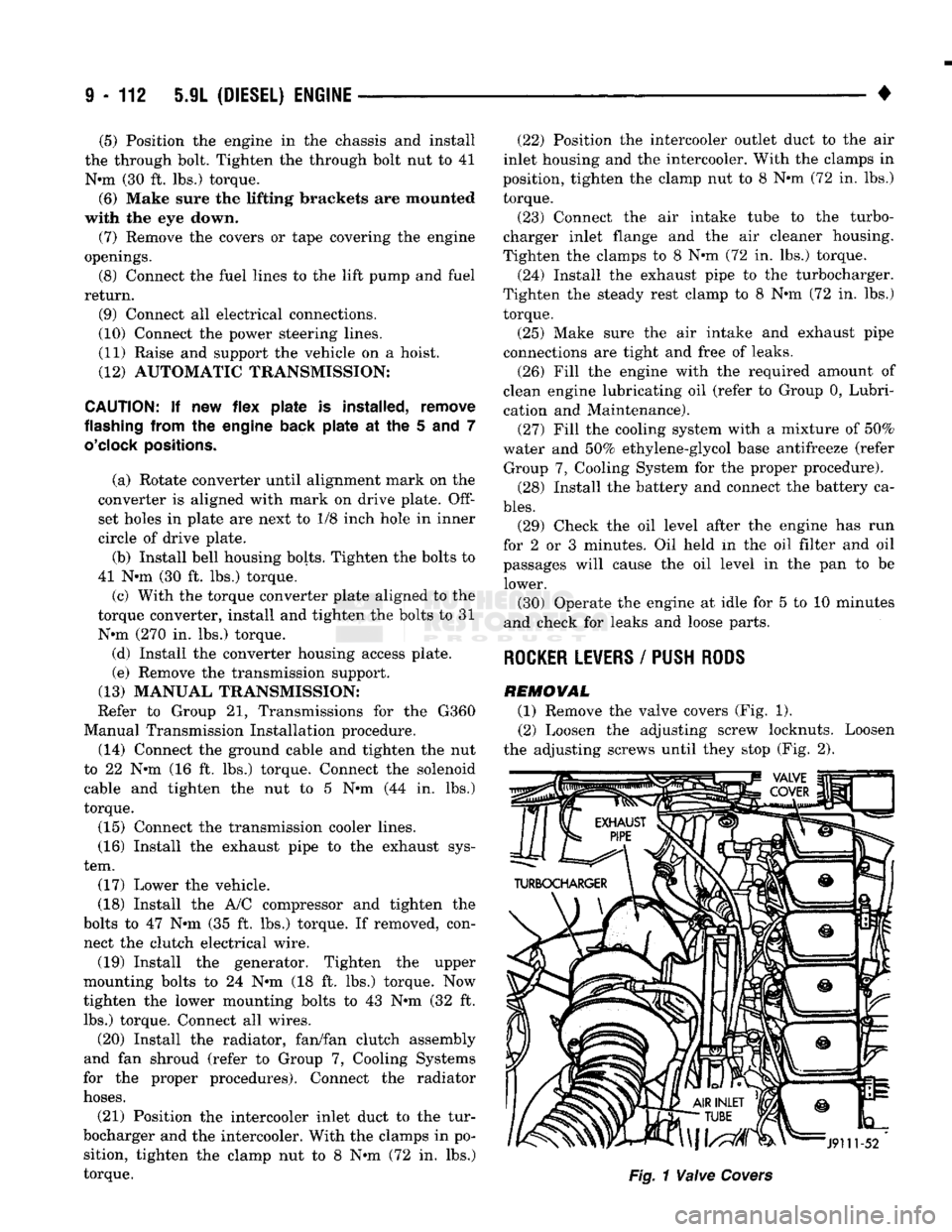
REMOVAL (1) Remove the valve covers (Fig. 1). (2) Loosen the adjusting screw locknuts. Loosen
the adjusting screws until they stop (Fig. 2).
Page 721 of 1502
9
- 116 5.9L
(DIESEL) ENGINE
•
CYLINDER HEAD
Fig. 11 Cylinder Head/Gasket Alignment J9109-36
Fig. 12 Cylinder Head Tightening Sequence
(7) Be sure to lubricate the push rod sockets with
clean engine oil.
(8) Install the rocker lever pedestal bolts and
tighten to 24 N*m (18 ft. lbs.) torque. (9) Adjust the valve clearance.
(10) Install the valve covers. Tighten the bolts to
24 N*m (18 ft. lbs.) torque.
(11) Install the injector nozzles and fuel lines (refer
to Group 14, Fuel System).
(12) Install the fuel filter (refer to Group 14, Fuel
System for the proper procedures). (13) Install the exhaust manifold (refer to Group
11,
Exhaust System and Intake Manifold).
(14) Install the turbocharger.
(15) Connect the radiator and heater hoses. (16) Fill the engine with new coolant or the clean
drained coolant (refer to Group 7, Cooling System for
the proper procedure). (17) Fill the engine with clean lubricating oil (re
fer to Group 0, Lubrication and Maintenance).
VALVES
AND VALVE
SPRINGS
REMOWAL
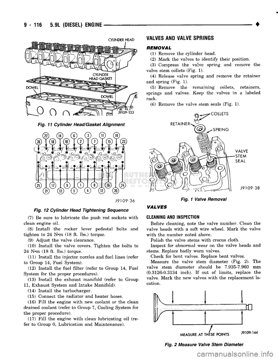
(1) Remove the cylinder head.
(2) Mark the valves to identify their position.
(3) Compress the valve spring and remove the
valve stem collets (Fig. 1). (4) Release valve spring and remove the retainer
and spring (Fig. 1).
(5) Remove the remaining collets, retainers,
springs and valves. Keep the valves in a labeled
rack.
(6) Remove the valve stem seals (Fig. 1). -38
Fig. 1 Valve Removal
WALVES
CLEANING AND INSPECTION
Before cleaning, note the valve number. Clean the
valve heads with a soft wire wheel. Mark the valve
with the numbet* noted above.
Polish the valve stems with crocus cloth.
Inspect for abnormal wear on the valve heads and
stems.
Replace badly worn valves. Check for bent valves. Replace bent valves.
Measure the valve stem diameter (Fig. 2). The
valve stem diameter should be 7.935-7.960 mm (0.3126-0.3134 inch). If out of limits, replace the
valve. Mark the new valves with the replacement lo cation. Ik 1
MEASURE
AT THESE POINTS
Fig. 2 Measure Valve Stem Diameter
Page 751 of 1502
9
- 148 5.9L
(DIESEL) ENGINE
• Make sure the idler gear pin is installed in the lo
cating bore in the cylinder block. (2) Install the pump. Tighten the oil pump mount
ing bolts in two steps and in the sequence shown (Fig. 2).
• Step
1—Tighten
to 5 N«m (44 in. lbs.) torque.
• Step 2-Tighten to 24 N*m (18 ft. lbs.) torque. (3) The back plate on the pump seats against the
bottom of the bore in the cylinder block. When the
pump is correctly installed, the flange on the pump will not touch the cylinder block.
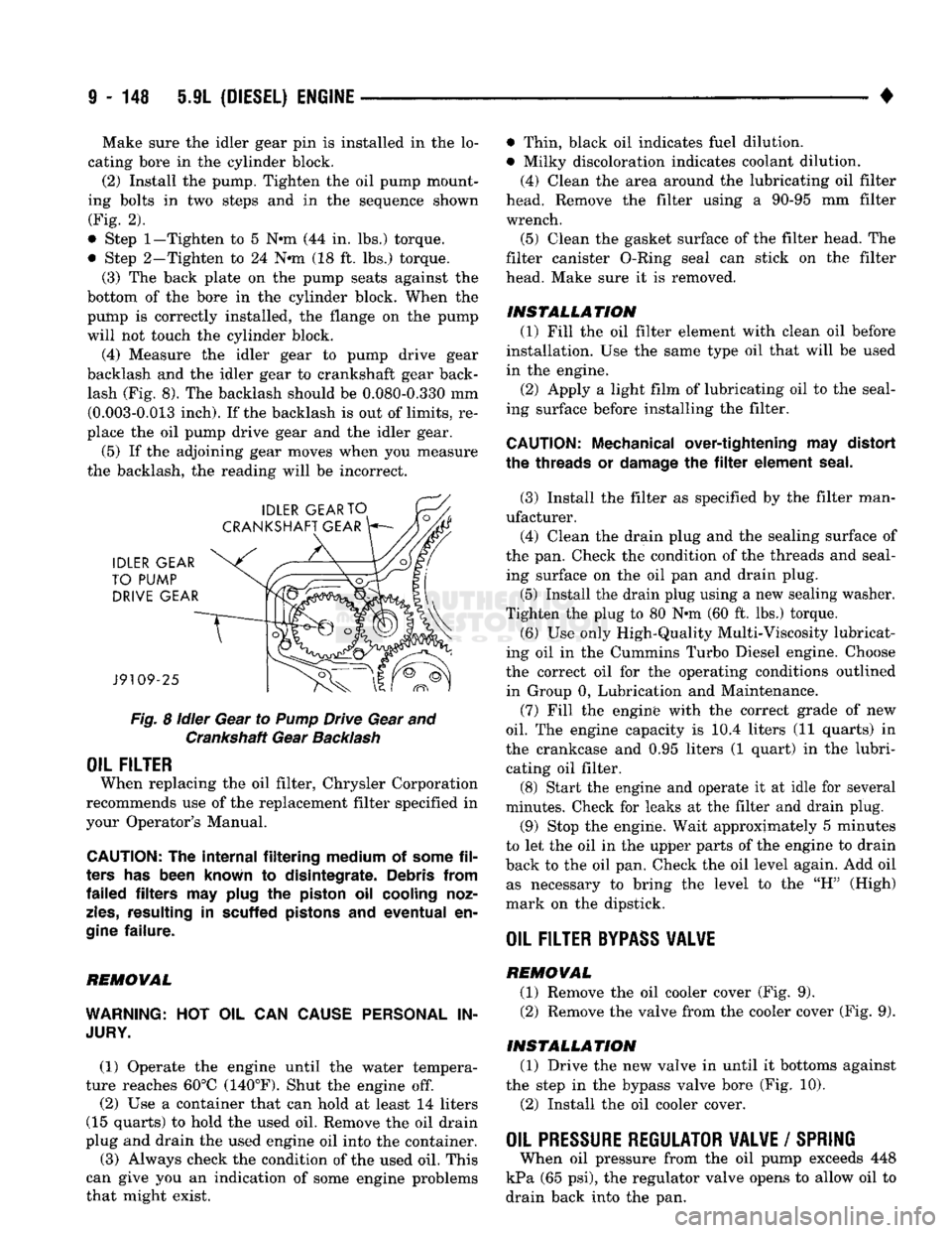
(4) Measure the idler gear to pump drive gear
backlash and the idler gear to crankshaft gear back lash (Fig. 8). The backlash should be 0.080-0.330 mm (0.003-0.013 inch). If the backlash is out of limits, re
place the oil pump drive gear and the idler gear.
(5) If the adjoining gear moves when you measure
the backlash, the reading will be incorrect.
Fig.
8
idler
Gear to
Pump
Drive Gear and Crankshaft Gear
Backlash
OIL FILTER
When replacing the oil filter, Chrysler Corporation
recommends use of the replacement filter specified in
your Operator's Manual.
CAUTION:
The
internal filtering medium
of
some
fil
ters
has
been known
to
disintegrate. Debris from
failed filters
may
plug
the
piston
oil
cooling noz
zles,
resulting
in
scuffed pistons
and
eventual
en
gine
failure.
REMOVAL
WARNING:
HOT OIL CAN
CAUSE PERSONAL
IN
JURY.
(1) Operate the engine until the water tempera
ture reaches 60°C (140°F). Shut the engine off.
(2) Use a container that can hold at least 14 liters
(15 quarts) to hold the used oil. Remove the oil drain
plug and drain the used engine oil into the container.
(3) Always check the condition of the used oil. This
can give you an indication of some engine problems
that might exist. • Thin, black oil indicates fuel dilution.
• Milky discoloration indicates coolant dilution.
(4) Clean the area around the lubricating oil filter
head. Remove the filter using a 90-95 mm filter
wrench.
(5) Clean the gasket surface of the filter head. The
filter canister O-Ring seal can stick on the filter
head. Make sure it is removed.
INSTALLATION (1) Fill the oil filter element with clean oil before
installation. Use the same type oil that will be used
in the engine.
(2) Apply a light film of lubricating oil to the seal
ing surface before installing the filter.
CAUTION:
Mechanical over-tightening
may
distort
the threads
or
damage
the filter
element seal.
(3) Install the filter as specified by the filter man
ufacturer. (4) Clean the drain plug and the sealing surface of
the pan. Check the condition of the threads and seal ing surface on the oil pan and drain plug.
(5) Install the drain plug using a new sealing washer.
Tighten the plug to 80 N-m (60 ft. lbs.) torque.
(6) Use only High-Quality Multi-Viscosity lubricat
ing oil in the Cummins Turbo Diesel engine. Choose
the correct oil for the operating conditions outlined in Group 0, Lubrication and Maintenance.
(7) Fill the enginfe with the correct grade of new
oil.
The engine capacity is i0.4 liters (11 quarts) in
the crankcase and 0.95 liters (1 quart) in the lubri cating oil filter. (8) Start the engine and operate it at idle for several
minutes. Check for leaks at the filter and drain plug.
(9) Stop the engine. Wait approximately 5 minutes
to let the oil in the upper parts of the engine to drain
back to the oil pan. Check the oil level again. Add oil as necessary to bring the level to the "H" (High)
mark on the dipstick.
OIL FILTER
BYPASS
VALWE
REMOVAL
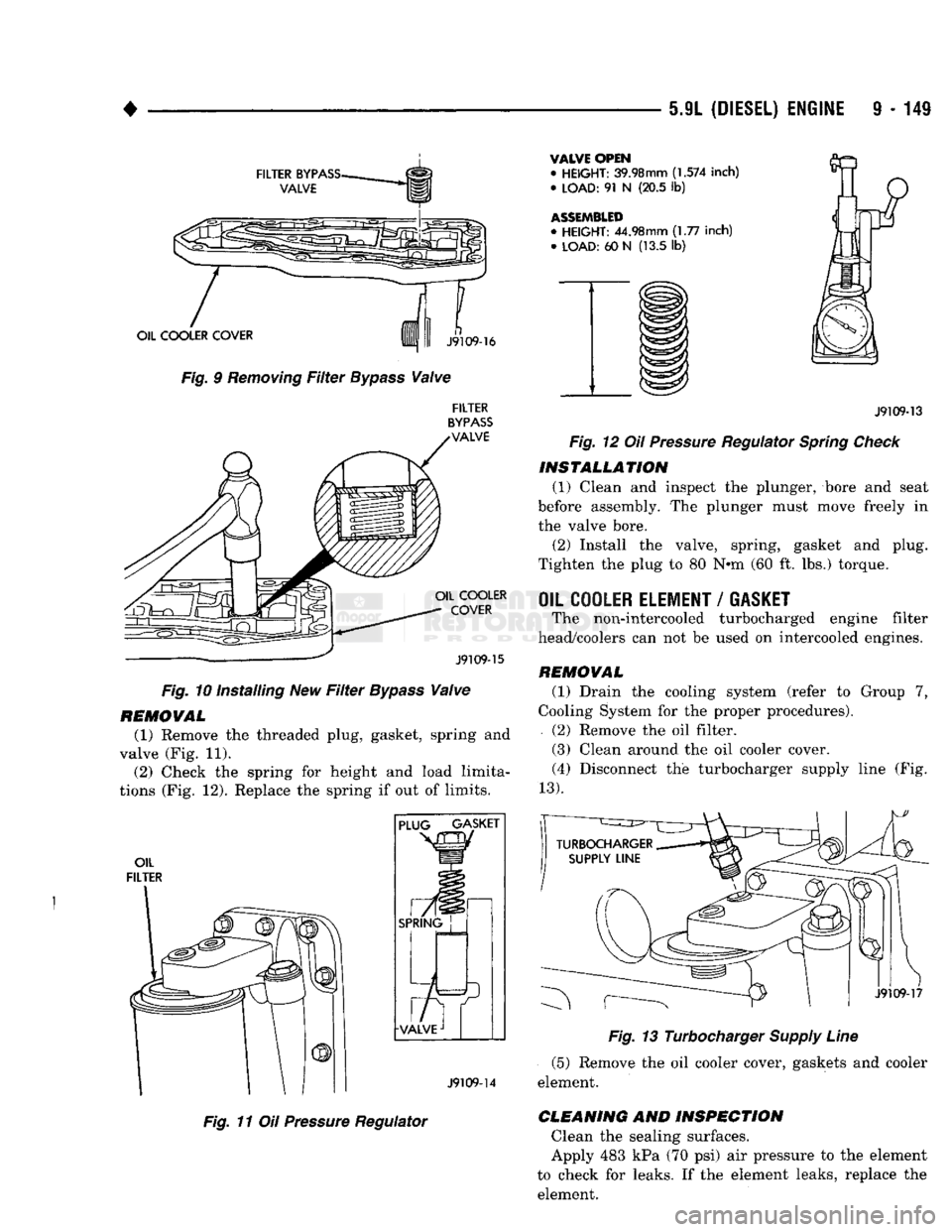
(1) Remove the oil cooler cover (Fig. 9). (2) Remove the valve from the cooler cover (Fig. 9).
INSTALLATION (1) Drive the new valve in until it bottoms against
the step in the bypass valve bore (Fig. 10).
(2) Install the oil cooler cover.
OIL PRESSURE REGULATOR VALVE
/
SPRING
When oil pressure from the oil pump exceeds 448
kPa (65 psi), the regulator valve opens to allow oil to
drain back into the pan.
Page 752 of 1502
5.9L
(DIESEL) ENGINE
9 - 149
FILTER
BYPASS-
VALVE
OIL COOLER COVER
Fig. 9
Removing
Filter
Bypass
Valve
n
J9109-16
FILTER
BYPASS
VALVE OIL COOLER
COVER
J9109-15
Fig. 10 Installing New
Filter
Bypass
Valve
REMOVAL
(1) Remove the threaded plug, gasket, spring and
valve (Fig. 11). (2) Check the spring for height and load limita
tions (Fig. 12). Replace the spring if out of limits.
OIL
FILTER PLUG GASKET
SPRING
J9109-14
Fig. 11 Oil
Pressure
Regulator
VALVE OPEN
•
HEIGHT:
39.98mm
(1.574
inch)
•
LOAD:
91 N (20.5 lb)
ASSEMBLED
•
HEIGHT:
44.98mm (1.77 inch) •
LOAD:
60 N (13.5 lb)
J9109-13
Fig. 12 Oil
Pressure
Regulator
Spring
Check
INSTALLATION
(1) Clean and inspect the plunger, bore and seat
before assembly. The plunger must move freely in
the valve bore.
(2) Install the valve, spring, gasket and plug.
Tighten the plug to 80 N*m (60 ft. lbs.) torque.
OIL COOLER ELEMENT
/
GASKET
The non-intercooled turbocharged engine filter
head/coolers can not be used on intercooled engines.
REMOVAL
(1) Drain the cooling system (refer to Group 7,
Cooling System for the proper procedures).
(2) Remove the oil filter.
(3) Clean around the oil cooler cover. (4) Disconnect the turbocharger supply line (Fig.
13).
J9109-17
Fig. 13 Turbocharger
Supply
Line
(5) Remove the oil cooler cover, gaskets and cooler
element.
CLEANING
AND
INSPECTION
Clean the sealing surfaces.
Apply 483 kPa (70 psi) air pressure to the element
to check for leaks. If the element leaks, replace the element.
Page 753 of 1502
9 - 150 5.9L
(DIESEL) ENGINE
•
INSTALLATION
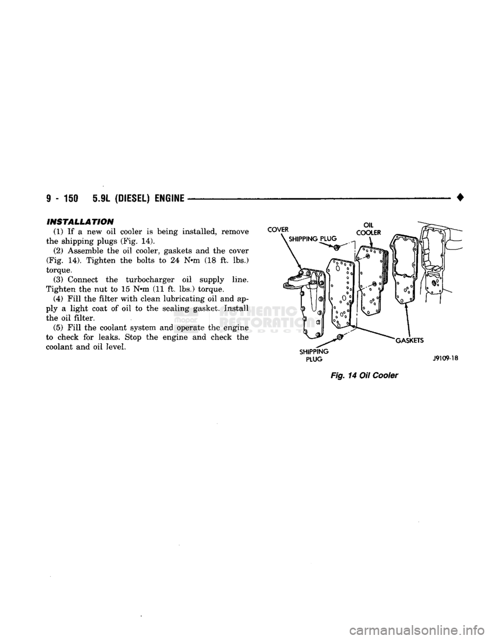
(1) If a new oil cooler is being installed, remove
the shipping plugs (Fig. 14). (2) Assemble the oil cooler, gaskets and the cover
(Fig. 14). Tighten the bolts to 24 N-m (18 ft. lbs.)
torque. (3) Connect the turbocharger oil supply line.
Tighten the nut to 15 N-m (11 ft. lbs.) torque. (4) Fill the filter with clean lubricating oil and ap
ply a light coat of oil to the sealing gasket. Install the oil filter. (5) Fill the coolant system and operate the engine
to check for leaks. Stop the engine and check the
coolant and oil level.
SHIPPING
PLUG
J9109-18
Fig.
14 Oil
Cooler
Page 756 of 1502
5.9L
(DIESEL)
ENGINE
9-153
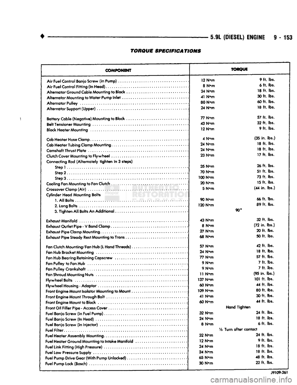
TORQUE
SPECIFICATIONS
COMPONENT
Air
Fuel
Control
Banjo Screw (In Pump) ....
Air
Fuel
Control
Fitting
(In
Head)
Alternator
Ground Cable Mounting to
Block
Alternator
Mounting to
Water
Pump
Inlet
..
Alternator
Pulley
Alternator
Support
(Upper)
Battery
Cable
(Negative)
Mounting to Block ,
Belt
Tensioner
Mounting
Block
Heater
Mounting
Cab
Heater
Hose
Clamp
Cab
Heater
Tubing
Clamp Mounting.......
Camshaft
Thrust
Plate
Clutch Cover Mounting to
Flywheel
...
Connecting Rod
(Alternately
tighten
in 3 steps) Step 1
Step 2
Step 3 .
Cooling Fan Mounting to
Fan
Clutch
Crossover
Clamp (Air)
Cylinder
Head
Mounting Bolts
1.
All
Bolts....
2.
Long
Bolts
.........
3.
Tighten
All
Bolts
An
Additional
Exhaust
Manifold
Exhaust
Outlet
Pipe
- V
Band
Clamp
Exhaust
Pipe
Clamp Mounting
Exhaust
Pipe
Steady
Rest
Mounting to Trans .
Fan
Clutch Mounting/Fan Hub
(L
Hand
Threads)..
Fan Hub
Bracket
Mounting
Fan Hub Bearing
Retaining
Capscrew
Fan
Pulley
to
Fan
Hub
Fan
Pulley
Crankshaft .
Fan
Shroud
Mounting Nuts
Flywheel
Bolts
Flywheel
Housing
- Adaptor
Front
Engine
Mount Isolator Mounting to Mount..
Front
Engine
Mount Through Bolt
Front
Engine
Mount to Block
Front
Oil
Filler
Pipe
-
Access
Cover
Fuel
Banjo Screw (In
Fuel
Pump)
Fuel
Banjo Screw (In
Head)
Fuel
Banjo Screw (In
Injector)
Fuel
Filter
Fuel
Heater
Assembly
Mounting
Fuel
Heater
Ground Mounting to
Intake
Manifold
Fuel
Link
Fitting
(High Pressure)
Fuel
Low Pressure Supply
Fuel
Pump
Drive
Gear
(With
Pump
Unlocked)
Fuel
Pump Lock (Bosch)
TORQUE
12 N-m 9 ft. lbs.
8 N-m 6 ft. lbs.
24 N-m 18 ft. lbs.
41 N*m 30 ft. lbs.
80 N-m 60 ft. lbs.
24 N-m 18 ft. lbs.
77 N-m 57 ft. lbs.
43 N-m 32 ft. lbs.
12 N-m 9 ft. lbs.
4 N-m (35 in. lbs.)
24 N-m 18 ft. lbs.
24 N-m 18 ft. lbs.
23 N-m 17 ft. lbs.
35 N-m 26 ft. lbs.
70 N-m 51 ft. lbs.
100 N-m 73 ft. lbs.
20 N-m 15 ft. lbs.
5
N-m (44 in. lbs.)
90 N-m 66 ft. lbs.
120 N-m 89 ft. lbs.
90°
43 N-m 32 ft. lbs.
8 N-m (72 in. lbs.)
27 N-m 20 ft. lbs.
68 N-m 50 ft. lbs.
57 N-m 42 ft. lbs.
24 N-m 18 ft. lbs.
77 N-m 57 ft. lbs.
9 N-m 7 ft. lbs.
9 N-m 7 ft. lbs.
11 N-m (95 in. lbs.)
137 N-m 101 ft. lbs.
60 N-m 44 ft. lbs.
109 N-m 80 ft. lbs.
41 N-m 30 ft. lbs.
60 N-m 44 ft. lbs.
Hand
Tighten
32 N-m 24 ft. lbs.
24 N-m 18 ft. lbs.
8 N-m 6 ft. lbs.
Vi
Turn
after
contact
32 N-m 24 ft. lbs.
12 N-m 9 ft. lbs.
24 N-m 18 ft. lbs.
24 N-m 18 ft. lbs.
65 N-m 48 ft. lbs.
30 N-m 22 ft. lbs.
J9109-261
Page 757 of 1502
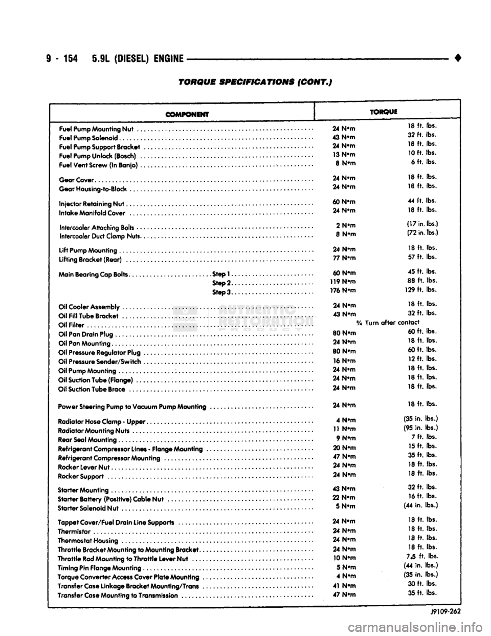
9
- 154 5.9L
(DIESEL)
ENGINE
TORQUE
SPECIFICATIONS
(CONT.J
COMPONENT
TORQUE
Fuel
Pump
Mounting
Nut
..
Fuel
Pump
Solenoid
Fuel
Pump
Support
Bracket
Fuel
Pump
Unlock
(Bosch)
.
Fuel
Vent
Screw
(In Banjo)
.
Gear
Cover
Gear
Housing-to-Block
Injector
Retaining Nut.
Intake
Manifold
Cover
Intercooler
Attaching
Bolts
•
•
Intercooler
Duct
Clamp
Nuts.
Lift
Pump
Mounting
Lifting Bracket (Rear)
..
Main
Bearing
Cap
Bolts.
Step!.
Step
2.
Steo3.
Oil
Cooler
Assembly
Oil
Fill
Tube Bracket
Oil
Filter
Oil
Pan
Drain
Plug
Oil
Pan
Mounting.........
Oil
Pressure
Regulator
Plug
Oil
Pressure
Sender/Switch
Oil
Pump
Mounting
Oil
Suction
Tube (Flange)
..
Oil
Suction
Tube
Brace
Power Steering
Pump
to
Vacuum
Pump
Mounting
Radiator Hose Clamp
-
Upper
Radiator Mounting Nuts Rear Seal Mounting
Refrigerant
Compressor
Lines
-
Flange Mounting
Refrigerant
Compressor
Mounting
Rocker Lever Nut
Rocker Support
Starter
Mounting
Starter
Battery
(Positive) Cable Nut
Starter
Solenoid Nut
Tappet
Cover/Fuel Drain Line Supports
Thermistor
,
Thermostat Housing
Throttle
Bracket Mounting to Mounting Bracket.
Throttle
Rod
Mounting to
Throttle
Lever Nut
...
Timing Pin Flange Mounting
Torque Converter
Access
Cover
Plate
Mounting
Transfer
Case
Linkage Bracket Mounting/Trans Transfer
Case
Mounting to
Transmission
..
24
N-m
18
ft.
lbs.
43
N-m
32 ft. lbs.
24
N-m
18
ft.
lbs.
13
N-m
10
ft. lbs.
8
N-m
6 ft. lbs.
24
N-m
18
ft.
lbs.
24
N-m
18
ft.
lbs.
60
N-m
44
ft.
lbs.
24
N-m
18
ft.
lbs.
2
N-m
(17
in.
lbs.)
8
N-m
(72
in.
lbs.)
24
N-m
18
ft.
lbs.
77
N-m
57
ft.
lbs.
60 N-m 45 ft. lbs.
119
N-m
88
ft.
lbs.
176 N-m 129
ft.
lbs.
24
N-m
18
ft.
lbs.
43
N-m
32
ft.
lbs.
Turn
after
contact
80 N-m 60 ft. lbs.
24
N-m
18
ft.
lbs.
80 N-m 60 ft. lbs.
16
N-m
12 ft. lbs.
24
N-m
18
ft.
lbs.
24
N-m
18
ft.
lbs.
24
N-m
18
ft.
lbs.
24
N-m
18
ft.
lbs.
4
N-m
(35 in. lbs.)
11
N-m
(95 in. lbs.)
9 N-m 7
ft.
lbs.
20
N-m
15
ft.
lbs.
47
N-m
35 ft. lbs.
24
N-m
18
ft.
lbs.
24
N-m
18
ft.
lbs.
43
N-m
32
ft.
lbs.
22
N-m
16
ft. lbs.
5
N-m
(44 in. lbs.)
24
N-m
18
ft.
lbs.
24
N-m
18
ft.
lbs.
24
N-m
18
ft.
lbs.
24
N-m
18
ft.
lbs.
10 N-m
73
ft.
lbs.
5
N-m
(44 in. lbs.)
4
N-m
(35
in. lbs.)
41
N-m
30 ft. lbs.
47
N-m
35 ft. lbs.
J9109-262
Page 800 of 1502
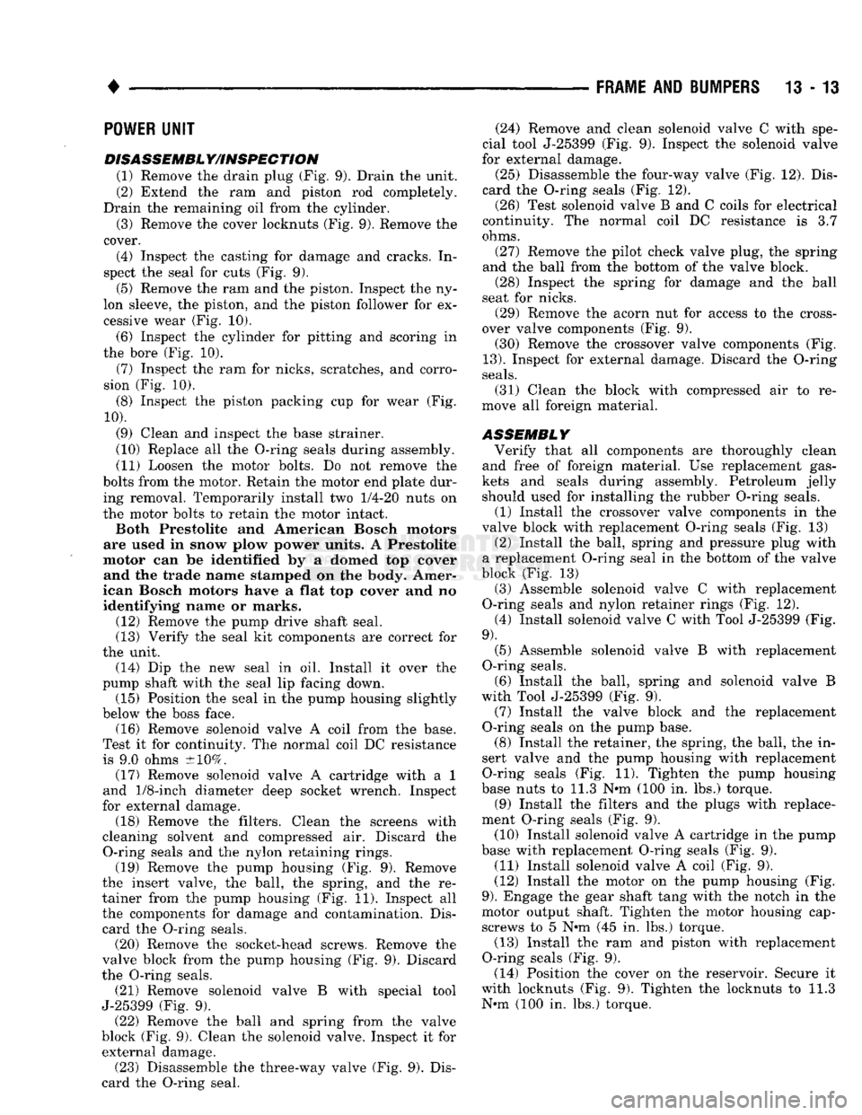
•
FRAME
AND
BUMPERS
13 - 13
POWER
UNIT
DISASSEMBL
Y/INSPECTION
(1) Remove the drain plug (Fig. 9). Drain the unit.
(2) Extend the ram and piston rod completely.
Drain the remaining oil from the cylinder.
(3) Remove the cover locknuts (Fig. 9). Remove the
cover.
(4) Inspect the casting for damage and cracks. In
spect the seal for cuts (Fig. 9).
(5) Remove the ram and the piston. Inspect the ny
lon sleeve, the piston, and the piston follower for ex cessive wear (Fig. 10).
(6) Inspect the cylinder for pitting and scoring in
the bore (Fig. 10).
(7) Inspect the ram for nicks, scratches, and corro
sion (Fig. 10).
(8) Inspect the piston packing cup for wear (Fig.
10).
(9) Clean and inspect the base strainer.
(10) Replace all the O-ring seals during assembly.
(11) Loosen the motor bolts. Do not remove the
bolts from the motor. Retain the motor end plate dur ing removal. Temporarily install two
1/4-20
nuts on
the motor bolts to retain the motor intact.
Both Prestolite and American Bosch motors
are used in snow plow power units. A Prestolite
motor can be identified by a domed top cover and the trade name stamped on the body. Amer
ican Bosch motors have a flat top cover and no
identifying name or marks. (12) Remove the pump drive shaft seal.
(13) Verify the seal kit components are correct for
the unit. (14) Dip the new seal in oil. Install it over the
pump shaft with the seal lip facing down. (15) Position the seal in the pump housing slightly
below the boss face. (16) Remove solenoid valve A coil from the base.
Test it for continuity. The normal coil DC resistance is 9.0 ohms ±10%. (17) Remove solenoid valve A cartridge with a 1
and
1/8-inch
diameter deep socket wrench. Inspect
for external damage. (18) Remove the filters. Clean the screens with
cleaning solvent and compressed air. Discard the O-ring seals and the nylon retaining rings. (19) Remove the pump housing (Fig. 9). Remove
the insert valve, the ball, the spring, and the re
tainer from the pump housing (Fig. 11). Inspect all the components for damage and contamination. Dis
card the O-ring seals. (20) Remove the socket-head screws. Remove the
valve block from the pump housing (Fig. 9). Discard
the O-ring seals. (21) Remove solenoid valve B with special tool
J-25399 (Fig. 9). (22) Remove the ball and spring from the valve
block (Fig. 9). Clean the solenoid valve. Inspect it for external damage. (23) Disassemble the three-way valve (Fig. 9). Dis
card the O-ring seal. (24) Remove and clean solenoid valve C with spe
cial tool J-25399 (Fig. 9). Inspect the solenoid valve
for external damage.
(25) Disassemble the four-way valve (Fig. 12). Dis
card the O-ring seals (Fig. 12). (26) Test solenoid valve B and C coils for electrical
continuity. The normal coil DC resistance is 3.7
ohms.
(27) Remove the pilot check valve plug, the spring
and the ball from the bottom of the valve block. (28) Inspect the spring for damage and the ball
seat for nicks. (29) Remove the acorn nut for access to the cross
over valve components (Fig. 9).
(30) Remove the crossover valve components (Fig.
13).
Inspect for external damage. Discard the O-ring
seals.
(31) Clean the block with compressed air to re
move all foreign material.
ASSEMBLY
Verify that all components are thoroughly clean
and free of foreign material. Use replacement gas
kets and seals during assembly. Petroleum jelly should used for installing the rubber O-ring seals.
(1) Install the crossover valve components in the
valve block with replacement O-ring seals (Fig. 13) (2) Install the ball, spring and pressure plug with
a replacement O-ring seal in the bottom of the valve
block (Fig. 13) (3) Assemble solenoid valve C with replacement
O-ring seals and nylon retainer rings (Fig. 12). (4) Install solenoid valve C with Tool J-25399 (Fig.
9).
(5) Assemble solenoid valve B with replacement
O-ring seals.
(6) Install the ball, spring and solenoid valve B
with Tool J-25399 (Fig. 9). (7) Install the valve block and the replacement
O-ring seals on the pump base. (8) Install the retainer, the spring, the ball, the in
sert valve and the pump housing with replacement
O-ring seals (Fig. 11). Tighten the pump housing
base nuts to 11.3 N*m (100 in. lbs.) torque. (9) Install the filters and the plugs with replace
ment O-ring seals (Fig. 9). (10) Install solenoid valve A cartridge in the pump
base with replacement O-ring seals (Fig. 9). (11) Install solenoid valve A coil (Fig. 9).
(12) Install the motor on the pump housing (Fig.
9).
Engage the gear shaft tang with the notch in the
motor output shaft. Tighten the motor housing cap- screws to 5 N#m (45 in. lbs.) torque. (13) Install the ram and piston with replacement
O-ring seals (Fig. 9). (14) Position the cover on the reservoir. Secure it
with locknuts (Fig. 9). Tighten the locknuts to 11.3 Nrn (100 in. lbs.) torque.