water pump DODGE TRUCK 1993 Service Manual Online
[x] Cancel search | Manufacturer: DODGE, Model Year: 1993, Model line: TRUCK, Model: DODGE TRUCK 1993Pages: 1502, PDF Size: 80.97 MB
Page 975 of 1502
19
- 14
STEERING
• (9) Install the fluid hoses to the power steering
pump, Tighten the pressure fitting at the pump to 30
N*m (22 ft. lbs.) torque.
(10) Install and clamp the hose on the vacuum
pump. (11) Fill the reservoir with power steering fluid
only. If necessary, refer to Pump Initial Operation
for detailed instructions.
(12) Start and run the engine. Check the operation
of the brakes, if necessary refer to Group 5, Brakes
for additional information.
PUMP REPLACEMENT—GASOLINE ENGINE
REMOVAL
WARNING:
DO NOT
REMOVE
THE
WATER PUMP COOLANT TUBE UNLESS
THE
COOLANT SYSTEM HAS BEEN DEPRESSUR1ZED
AND
DRAINED*
WARNING:
DO NOT
ATTEMPT
TO
REMOVE
THE
PUMP
WITHOUT
REMOVING
THE
BELT FIRST.
THE
AUTOMATIC TENSIONER
IS
UNDER
A
HIGH
SPRING
LOAD.
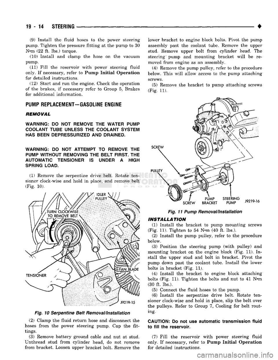
(1) Remove the serpentine drive belt. Rotate ten
sioner clock-wise and hold in place, and remove belt
(Fig. 10).
Fig.
10 Serpentine Belt Removal/Installation
(2) Clamp the fluid return hose and disconnect the
hoses from the power steering pump. Cap the fit
tings.
(3) Remove battery ground cable and nut at stud.
Unthread stud from cylinder head, do not remove
from bracket. Loosen upper bracket bolt. Remove the lower bracket to engine block bolts. Pivot the pump
assembly past the coolant tube. Remove the upper
stud. Remove upper bolt from cylinder head. The
steering pump and mounting bracket will be re
moved from engine as an assembly.
(4) Remove the pump pulley, refer to the procedure
below. This will allow access to the pump attaching screws.
(5)
Remove the bracket to pump attaching screws
(Fig. 11).
Fig.
11
Pump
Removal/Installation
INSTALLATION
(1) Install the bracket to pump mounting screws
(Fig. 11). Tighten to 54 N-m (40 ft. lbs.). (2) Install the pump pulley, refer to the procedure
below.
(3) Position the steering pump (with pulley) and
mounting bracket on the engine block (Fig. 11). In stall the upper stud and bolt in bracket. Pivot the
pump down past the coolant tube. Install the lower
bolts in bracket (Fig. 11). (4) Install the bracket to engine block attaching
bolts (Fig. 11). Tighten the bolts and nut to 41 N*m (30 ft. lbs.).
(5) Connect the fluid hoses to the pump. (6) Install the serpentine drive belt. Rotate ten
sioner clock-wise and hold in place, slip the belt over
the pulleys. Refer to Group 7, Cooling for belt rout ing.
CAUTION:
Do not use
automatic
transmission
fluid
to
fill the
reservoir.
(7) Fill the reservoir with power steering fluid
only. If necessary, refer to Pump Initial Operation
for detailed instructions.
Page 1094 of 1502
•
AUTOMATIC
TRANSMISSION-32RH/3IRH/37RH/42RH/48RH
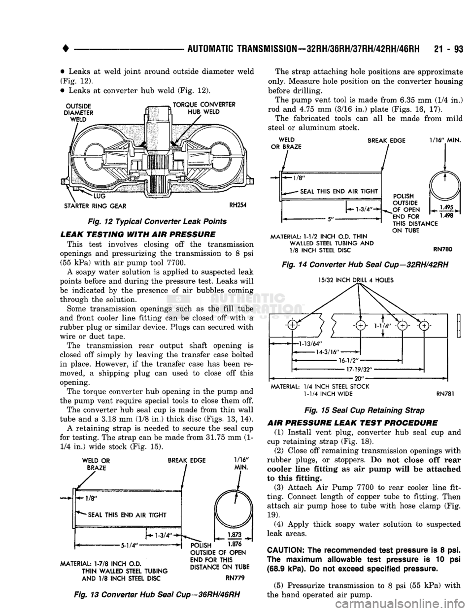
21 - 13 • Leaks at weld joint around outside diameter weld
(Fig. 12).
• Leaks at converter hub weld (Fig. 12).
OUTSIDE
DIAMETER
WELD
TORQUE CONVERTER
HUB WELD
"LUG
STARTER RING GEAR
RH254
Fig.
12 Typical Converter
Leak
Points
LEAK
TESTING
WITH AIR
PRESSURE
This test involves closing off the transmission
openings and pressurizing the transmission to 8 psi (55 kPa) with air pump tool 7700.
A soapy water solution is applied to suspected leak
points before and during the pressure test. Leaks will
be indicated by the presence of air bubbles coming
through the solution.
Some transmission openings such as the fill tube
and front cooler line fitting can be closed off with a
rubber plug or similar device. Plugs can secured with
wire or duct tape.
The transmission rear output shaft opening is
closed off simply by leaving the transfer case bolted
in place. However, if the transfer case has been re
moved, a shipping plug can used to close off this
opening. The torque converter hub opening in the pump and
the pump vent require special tools to close them off.
The converter hub seal cup is made from thin wall
tube and a 3.18 mm (1/8 in.) thick disc (Figs. 13, 14).
A retaining strap is needed to secure the seal cup
for testing. The strap can be made from 31.75 mm (1- 1/4 in.) wide stock (Fig. 15).
WELD OR
BRAZE
BREAK
EDGE
1/16"
MIN.
MATERIAL: 1-7/8 INCH O.D.
THIN
WALLED STEEL TUBING
AND 1/8 INCH STEEL DISC OUTSIDE OF OPEN
END FOR THIS
DISTANCE ON TUBE
RN779 The strap attaching hole positions are approximate
only. Measure hole position on the converter housing
before drilling.
The pump vent tool is made from 6.35 mm (1/4 in.)
rod and 4.75 mm (3/16 in.) plate (Figs. 16, 17). The fabricated tools can all be made from mild
steel or aluminum stock. WELD
OR BRAZE BREAK EDGE 1/16" MIN.
-«-l/8"
• SEAL THIS END AIR TIGHT
1-3/4"-*-
•
5"-
MATERIAL: 1-1/2 INCH O.D. THIN WALLED STEEL TUBING AND 1/8 INCH STEEL DISC POLISH
OUTSIDE
„OF OPEN
"END
FOR
THIS DISTANCE
ON TUBE
RN780
Fig.
14 Converter Hub
Seal
Cup-32RH/42RH
15/32 INCH DRILL 4 HOLES
MATERIAL: 1/4 INCH STEEL STOCK 1-1/4 INCH WIDE RN781
Fig.
13 Converter Hub
Seal
Cup-36RH/46RH
Fig.
15
Seal
Cup Retaining Strap
AIR
PRESSURE
LEAK
TEST
PROCEDURE
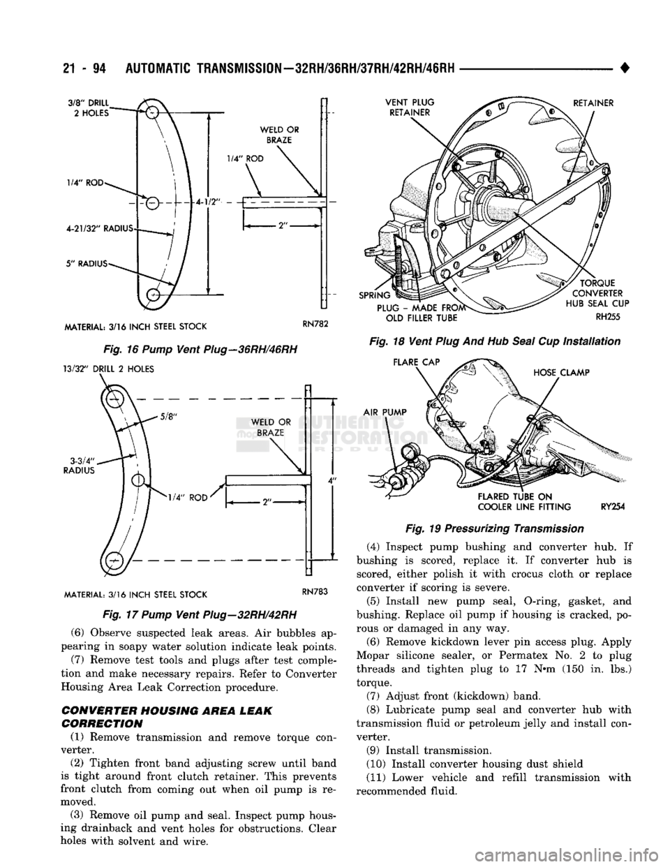
(1) Install vent plug, converter hub seal cup and
cup retaining strap (Fig. 18).
(2) Close off remaining transmission openings with
rubber plugs, or stoppers. Do not close off rear cooler line fitting as air pump will be attached
to this fitting.
(3) Attach Air Pump 7700 to rear cooler line fit
ting. Connect length of copper tube to fitting. Then attach air pump hose to tube with hose clamp (Fig.
19).
(4) Apply thick soapy water solution to suspected
leak areas.
CAUTION:
The
recommended
test
pressure
is 8
psi.
The
maximum
allowable
test
pressure
is 10 psi
(68.9 kPa).
Do not
exceed
specified
pressure.
(5) Pressurize transmission to 8 psi (55 kPa) with
the hand operated air pump.
Page 1095 of 1502
21
- 14
AUTOMATIC TRANSMISSION—32RH/36RH/37RH/42RH/46RH
•
MATERIAL:
3/16
INCH
STEEL
STOCK
Fig. 16 Pump Vent Piug-36RH/46RH
13/32" DRILL
2
HOLES MATERIAL:
3/16
INCH
STEEL
STOCK
KN/aj
Fig. 17 Pump Vent Plug-32RH/42RH
(6) Observe suspected leak areas. Air bubbles ap
pearing in soapy water solution indicate leak points.
(7) Remove test tools and plugs after test comple
tion and make necessary repairs. Refer to Converter Housing Area Leak Correction procedure.
CONVERTER HOUSING AREA LEAK
CORRECTION
(1) Remove transmission and remove torque con
verter.
(2) Tighten front band adjusting screw until band
is tight around front clutch retainer. This prevents
front clutch from coming out when oil pump is re
moved.
(3) Remove oil pump and seal. Inspect pump hous
ing drainback and vent holes for obstructions. Clear
holes with solvent and wire.
COOLER
LINE
FITTING
RY254
Fig. 19 Pressurizing Transmission (4) Inspect pump bushing and converter hub. If
bushing is scored, replace it. If converter hub is scored, either polish it with crocus cloth or replace
converter if scoring is severe.
(5) Install new pump seal, O-ring, gasket, and
bushing. Replace oil pump if housing is cracked, po
rous or damaged in any way.
(6)
Remove kickdown lever pin access plug. Apply
Mopar silicone sealer, or Permatex No. 2 to plug
threads and tighten plug to 17 N*m (150 in. lbs.) torque.
(7) Adjust front (kickdown) band.
(8) Lubricate pump seal and converter hub with
transmission fluid or petroleum jelly and install con
verter.
(9) Install transmission.
(10) Install converter housing dust shield
(11) Lower vehicle and refill transmission with
recommended fluid.
Page 1381 of 1502
22-12
WHEELS
AND
TIRES
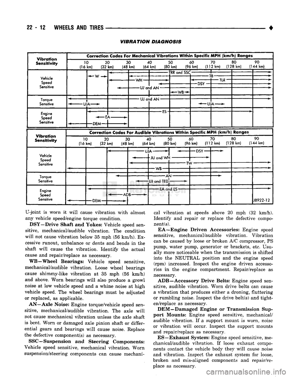
VIBRATION
DIAGNOSIS
Vibration
Sensitivity
Correction
Codes
For
Mechanical
Vibrations
Within
Specific
MPH
(km/h)
Ranges
10
(16km)
20
(32 km) 30
(48 km) 40
(64 km) 50
(80 km) 60
(96 km) 70
(112 km) 80
(128 km) 90
(144 km) Vehicle
Speed
Sensitive
•W
-WH-
-TRR
and
SSC-
-UJ
and AN-
-WB-
-TB-
-DSY
•TLR-
Torque
Sensitive
I
-UJA-
•
UJ
and AN
•
•UJA-
Engine
Speed
Sensitive
•ES
•EA-
•DEM-
Vibration
Sensitivity
Correction
Codes
For
Audible
Vibrations
Within
Specific
MPH
(km/h)
Ranges
10
(16 km) 20
(32 km) 30
(48 km) 40
(64 km) 50
(80 km) 60
(96 km) 70
(112 km) 80
(128 km) 90
(144 km)
Vehicle
Speed
Sensitive
•UJA-
JU
and WH
•DSY"
-TW-
•WB-
Torque
Sensitive
-AN
*
-UJ
and
TED,
Engine
Speed
Sensitive
•
EA
and
ES-
-ADB-
-DEM-
J8922-12
U-joint is worn it will cause vibration with almost
any vehicle speed/engine torque condition. DSY—Drive Shaft and Yokes: Vehicle speed sen
sitive, mechanical/audible vibration. The condition
will not cause vibration below 35 mph (56 km/h). Ex
cessive runout, unbalance or dents and bends in the shaft will cause the vibration. Identify the actual
cause and repair/replace as necessary.
WB—Wheel Bearings: Vehicle speed sensitive,
mechanical/audible vibration. Loose wheel bearings
cause shimmy-like vibration at 35 mph (56 km/h)
and above. Worn bearings will also produce a growl
noise at low vehicle speed and a whine noise at high
vehicle speed. The wheel bearings must be adjusted
or replaced, as applicable.
AN—Axle Noise: Engine torque/vehicle speed sen
sitive, mechanical/audible vibration. The axle will
not cause mechanical vibration unless the axle shaft
is bent. Worn or damaged axle pinion shaft or differ
ential gears and bearings will cause noise. Replace
the defective component(s) as necessary.
SSC—Suspension and Steering Components:
Vehicle speed sensitive, mechanical vibration. Worn
suspension/steering components can cause mechani cal vibration at speeds above 20 mph (32 km/h).
Identify and repair or replace the defective compo
nent
(s).
EA—Engine Driven Accessories: Engine speed
sensitive, mechanical/audible vibration. Vibration
can be caused by loose or broken A/C compressor, PS
pump, water pump, generator or brackets, etc. Usu ally more noticeable when the transmission is shifted
into the NEUTRAL position and the engine speed (rpm) increased. Inspect the engine driven accesso
ries in the engine compartment. Repair/replace as
necessary.
ADB—Accessory Drive Belts: Engine speed sen
sitive, audible vibration. Worn drive belts can cause
a vibration that produces either a droning, fluttering
or rumbling noise. Inspect the drive belt(s) and tight
en/replace as necessary.
DEM—Damaged Engine or Transmission Sup
port Mounts: Engine speed sensitive, mechanical/ audible vibration. If a support mount is worn, noise
or vibration will occur. Inspect the support mounts and repair/replace as necessary.
ES—Exhaust System: Engine speed sensitive, me
chanical/audible vibration. If loose exhaust compo
nents contact the vehicle body they will cause noise
and vibration. Inspect the exhaust system for loose,
broken and mis-aligned components and repair/re place as necessary.
Page 1441 of 1502
24
- 4
HEATING
AND
AIR
CONDITIONING
•
(1) Possible location or cause of blower motor vi
bration are as follows:
(a) Blower motor assembly loose in heater A/C
housing.
(b) Blower wheel loose on motor shaft.
(c) Blower wheel out of balance or bent.
(d) Blower motor defective.
(2) Possible location or cause of blower motor noise
are as follows: (To verify blower noise disconnect blower motor wire lead connector and operate heater
or A/C system. If noise goes away, proceed with pro
cedure.)
(a) Refer to vibration section of this procedure.
(b) Foreign material in Heater-A/C housing
around blower wheel.
(c) Blower wheel rubbing Heater-A/C housing.
(d) Blower motor defective.
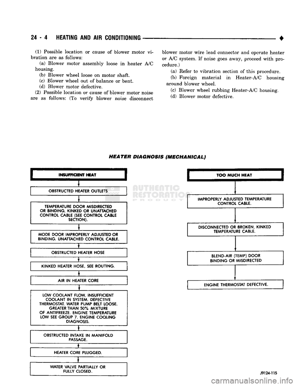
HEATER
DIAGNOSIS
(MECHANICAL)
INSUFFICIENT
HEAT
OBSTRUCTED HEATER OUTLETS
TEMPERATURE DOOR MISDIRECTED
OR BINDING, KINKED
OR
UNATTACHED
CONTROL CABLE (SEE CONTROL CABLE SECTION).
MODE DOOR IMPROPERLY ADJUSTED OR
BINDING. UNATTACHED CONTROL
CABLE.
±
OBSTRUCTED HEATER HOSE
•
KINKED HEATER HOSE, SEE ROUTING.
±
AIR
IN
HEATER CORE
LOW COOLANT FLOW, INSUFFICIENT COOLANT
IN
SYSTEM. DEFECTIVE
THERMOSTAT. WATER PUMP BELT LOOSE. GREATER
THAN
50%
MIXTURE
OF ANTIFREEZE. ENGINE TEMPERATURE LOW SEE GROUP
7.
ENGINE COOLING
DIAGNOSIS.
•
OBSTRUCTED INTAKE
IN
MANIFOLD
PASSAGE.
1_
HEATER CORE PLUGGED.
WATER VALVE PARTIALLY
OR
FULLY
CLOSED.
TOO
MUCH
HEAT
IMPROPERLY ADJUSTED TEMPERATURE CONTROL
CABLE.
DISCONNECTED
OR
BROKEN,
KINKED TEMPERATURE
CABLE.
BLEND-AIR
(TEMP)
DOOR
BINDING OR MISDIRECTED
ENGINE THERMOSTAT DEFECTIVE.
J9124-115
Page 1450 of 1502
•
HEATING
AND AIR
CONDITIONING
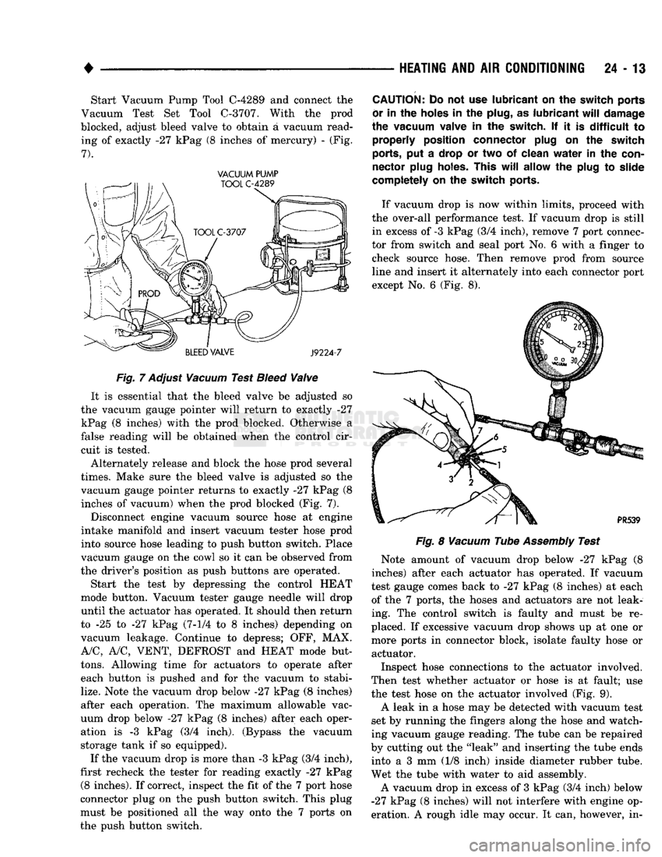
24 - 13 Start Vacuum Pump Tool
C-4289
and connect the
Vacuum Test Set Tool
C-3707.
With the prod
blocked, adjust bleed valve to obtain a vacuum read ing of exactly -27 kPag (8 inches of mercury) - (Fig.
7).
VACUUM PUMP
Fig.
7
Adjust
Vacuum
Test
Bleed
Valve
It is essential that the bleed valve be adjusted so
the vacuum gauge pointer will return to exactly -27 kPag (8 inches) with the prod blocked. Otherwise a
false reading will be obtained when the control cir
cuit is tested.
Alternately release and block the hose prod several
times.
Make sure the bleed valve is adjusted so the vacuum gauge pointer returns to exactly -27 kPag (8 inches of vacuum) when the prod blocked (Fig. 7).
Disconnect engine vacuum source hose at engine
intake manifold and insert vacuum tester hose prod
into source hose leading to push button switch. Place
vacuum gauge on the cowl so it can be observed from
the driver's position as push buttons are operated.
Start the test by depressing the control HEAT
mode button. Vacuum tester gauge needle will drop
until the actuator has operated. It should then return
to -25 to -27 kPag
(7-1/4
to 8 inches) depending on
vacuum leakage. Continue to depress; OFF, MAX.
A/C,
A/C,
VENT,
DEFROST
and
HEAT
mode but
tons.
Allowing time for actuators to operate after each button is pushed and for the vacuum to stabi
lize.
Note the vacuum drop below -27 kPag (8 inches)
after each operation. The maximum allowable vac
uum drop below -27 kPag (8 inches) after each oper ation is -3 kPag (3/4 inch). (Bypass the vacuum
storage tank if so equipped).
If the vacuum drop is more than -3 kPag (3/4 inch),
first recheck the tester for reading exactly -27 kPag
(8
inches). If correct, inspect the fit of the 7 port hose
connector plug on the push button switch. This plug
must be positioned all the way onto the 7 ports on
the push button switch.
CAUTION:
Do not use
lubricant
on the
switch ports
or
in the
holes
in the
plug,
as
lubricant
will
damage
the vacuum valve
in the
switch.
If it is
difficult
to
properly position connector plug
on the
switch
ports,
put a
drop
or two of
clean
water
in the
con
nector plug holes. This
will
allow
the
plug
to
slide
completely
on the
switch ports.
If vacuum drop is now within limits, proceed with
the over-all performance test. If vacuum drop is still in excess of
-3
kPag (3/4 inch), remove 7 port connec
tor from switch and seal port No. 6 with a finger to check source hose. Then remove prod from source
line and insert it alternately into each connector port
except No. 6 (Fig. 8).
Fig.
8
Vacuum
Tube
Assembly
Test
Note amount of vacuum drop below -27 kPag (8
inches) after each actuator has operated. If vacuum
test gauge comes back to -27 kPag (8 inches) at each of the 7 ports, the hoses and actuators are not leak
ing. The control switch is faulty and must be re
placed. If excessive vacuum drop shows up at one or
more ports in connector block, isolate faulty hose or actuator.
Inspect hose connections to the actuator involved.
Then test whether actuator or hose is at fault; use
the test hose on the actuator involved (Fig. 9).
A leak in a hose may be detected with vacuum test
set by running the fingers along the hose and watch
ing vacuum gauge reading. The tube can be repaired
by cutting out the "leak" and inserting the tube ends into a 3 mm (1/8 inch) inside diameter rubber tube.
Wet the tube with water to aid assembly.
A vacuum drop in excess of 3 kPag (3/4 inch) below
-27
kPag (8 inches) will not interfere with engine op
eration. A rough idle may occur. It can, however, in-