battery capacity DODGE TRUCK 1993 Service Repair Manual
[x] Cancel search | Manufacturer: DODGE, Model Year: 1993, Model line: TRUCK, Model: DODGE TRUCK 1993Pages: 1502, PDF Size: 80.97 MB
Page 39 of 1502
0
- 21
LUBRICATION
AND
MAINTENANCE
• SERVICE INFORMATION
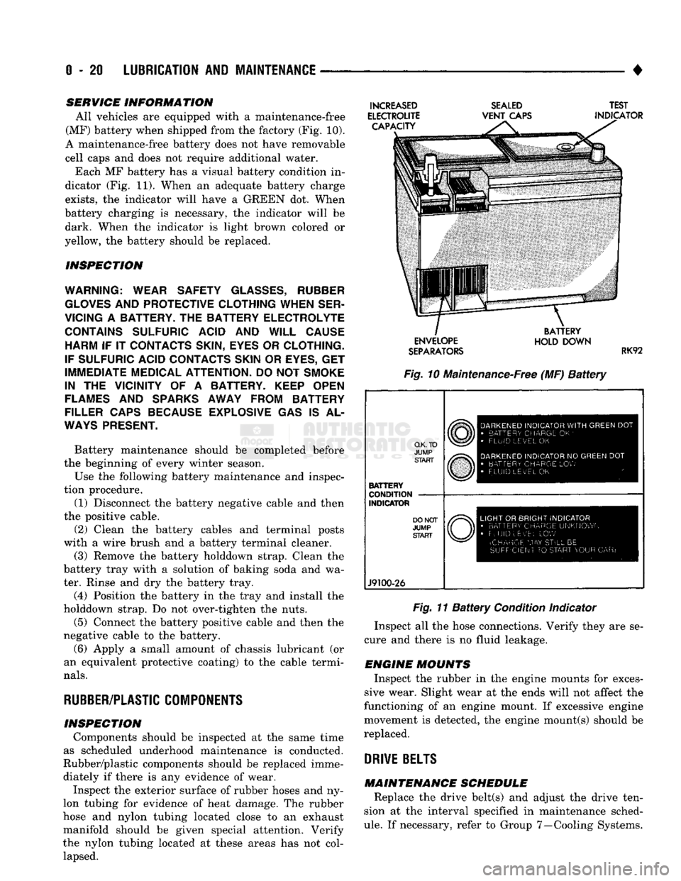
All vehicles are equipped with a maintenance-free
(MF) battery when shipped from the factory (Fig. 10).
A maintenance-free battery does not have removable
cell caps and does not require additional water. Each MF battery has a visual battery condition in
dicator (Fig. 11). When an adequate battery charge
exists,
the indicator will have a GREEN dot. When
battery charging is necessary, the indicator will be dark. When the indicator is light brown colored or
yellow, the battery should be replaced.
INSPECTION
WARNING; WEAR SAFETY
GLASSES,
RUBBER
GLOVES
AND
PROTECTIVE CLOTHING WHEN SER
VICING
A
BATTERY.
THE
BATTERY ELECTROLYTE CONTAINS SULFURIC ACID
AND
WILL CAUSE HARM
IF IT
CONTACTS SKIN, EYES
OR
CLOTHING.
IF SULFURIC ACID CONTACTS SKIN
OR
EYES,
GET
IMMEDIATE MEDICAL ATTENTION.
DO
NOT
SMOKE
IN
THE
VICINITY
OF A
BATTERY. KEEP OPEN
FLAMES
AND
SPARKS AWAY FROM BATTERY
FILLER CAPS BECAUSE EXPLOSIVE
GAS IS AL
WAYS
PRESENT.
Battery maintenance should be completed before
the beginning of every winter season.
Use the following battery maintenance and inspec
tion procedure. (1) Disconnect the battery negative cable and then
the positive cable.
(2) Clean the battery cables and terminal posts
with a wire brush and a battery terminal cleaner. (3) Remove the battery holddown strap. Clean the
battery tray with a solution of baking soda and wa
ter. Rinse and dry the battery tray.
(4) Position the battery in the tray and install the
holddown strap. Do not over-tighten the nuts.
(5) Connect the battery positive cable and then the
negative cable to the battery.
(6) Apply a small amount of chassis lubricant (or
an equivalent protective coating) to the cable termi
nals.
RUBBER/PLASTIC
COMPONENTS
INSPECTION Components should be inspected at the same time
as scheduled underhood maintenance is conducted.
Rubber/plastic components should be replaced imme diately if there is any evidence of wear. Inspect the exterior surface of rubber hoses and ny
lon tubing for evidence of heat damage. The rubber
hose and nylon tubing located close to an exhaust
manifold should be given special attention. Verify
the nylon tubing located at these areas has not col lapsed.
INCREASED
ELECTROUTE CAPACITY
SEALED
VENT
CAPS TEST
INDICATOR ENVELOPE
SEPARATORS
BATTERY
HOLD DOWN
RK92
Fig. 10 Maintenance-Free (MF)
Battery
O.K. TO
JUMP START
BATTERY
CONDITION
INDICATOR
J9100-26
DARKENED
INDICATOR
WITH
GREEN
DOT
•
BATTERY CHARGE
OK '
•
FLUID LEVEL
OK
DARKENED
INDICATOR
NO
GREEN
DOT
•
BATTERY CHARGE
LOW
FLUID LEVEL
OK
LIGHT
OR
BRIGHT INDICATOR
•
BATTERY CHARGE UNKNOWN
•
FLUID uEv'EL
LOW
(CHARGE
MAY
STILL
BE
SUFFICIENT
TO
START YOUR
CAR)
Fig. 11
Battery
Condition Indicator
Inspect all the hose connections. Verify they are se
cure and there is no fluid leakage.
ENGINE MOUNTS Inspect the rubber in the engine mounts for exces
sive wear. Slight wear at the ends will not affect the
functioning of an engine mount. If excessive engine
movement is detected, the engine mount(s) should be
replaced.
DRIVE
BELTS
MAINTENANCE SCHEDULE Replace the drive belt(s) and adjust the drive ten
sion at the interval specified in maintenance sched
ule.
If necessary, refer to Group 7—Cooling Systems.
Page 324 of 1502
•
ELECTRICAL
8A - 3
Fig.
3
Battery
Construction
and
Test Indicator
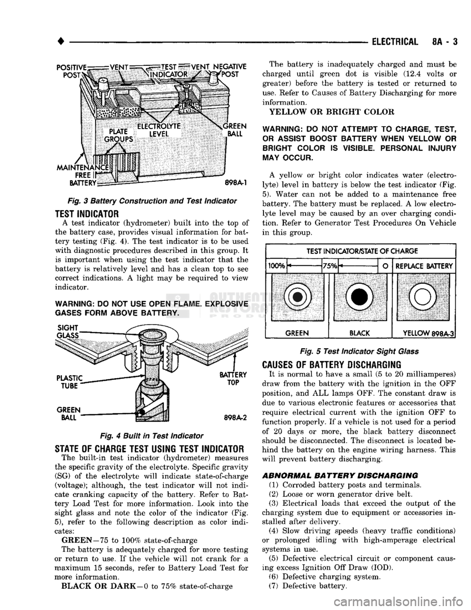
TEST INDICATOR
A test indicator (hydrometer) built into
the top of
the battery case, provides visual information
for
bat
tery testing (Fig.
4). The
test indicator
is to be
used with diagnostic procedures described
in
this group.
It
is important when using
the
test indicator that
the
battery
is
relatively level
and has a
clean
top to see
correct indications.
A
light
may be
required
to
view
indicator.
WARNING:
DO
NOT USE
OPEN FLAME. EXPLOSIVE
GASES
FORM ABOVE BATTERY.
Fig.
4
Built in Test Indicator
STATE
OF
CHARGE TEST USING TEST INDICATOR
The built-in test indicator (hydrometer) measures
the specific gravity
of
the electrolyte. Specific gravity (SG)
of the
electrolyte will indicate state-of-charge
(voltage); although,
the
test indicator will
not
indi
cate cranking capacity
of the
battery. Refer
to
Bat
tery Load Test
for
more information. Look into
the
sight glass
and
note
the
color
of the
indicator
(Fig.
5),
refer
to the
following description
as
color indi
cates:
GREEN-75
to
100% state-of-charge
The battery
is
adequately charged
for
more testing
or return
to use. If the
vehicle will
not
crank
for a
maximum
15
seconds, refer
to
Battery Load Test
for
more information. BLACK
OR
DARK—0
to
75% state-of-charge The battery
is
inadequately charged
and
must
be
charged until green
dot is
visible
(12.4
volts
or
greater) before
the
battery
is
tested
or
returned
to
use.
Refer
to
Causes
of
Battery Discharging
for
more information.
YELLOW
OR
BRIGHT COLOR
WARNING:
DO NOT
ATTEMPT
TO
CHARGE, TEST,
OR
ASSIST
BOOST BATTERY WHEN YELLOW
OR
BRIGHT COLOR
IS
VISIBLE. PERSONAL INJURY
MAY OCCUR.
A yellow
or
bright color indicates water (electro
lyte) level
in
battery
is
below
the
test indicator
(Fig.
5).
Water
can not be
added
to a
maintenance free
battery.
The
battery must
be
replaced.
A low
electro lyte level
may be
caused
by an
over charging condi
tion. Refer
to
Generator Test Procedures
On
Vehicle in this group.
TEST INDICATOR/STATE
OF
CHARGE
IfVW,
"TCfV
REPLACE BATTERY
lUUTu
/Otu L
f
REPLACE BATTERY
SBl
ill,
iMMiMMMMSMM^MM
GREEN BLACK
YELLOW
898A-3
Fig.
5
Test Indicator
Sight Glass
CAUSES
OF
BATTERY DISCHARGING
It
is
normal
to
have
a
small
(5 to 20
milliamperes)
draw from
the
battery with
the
ignition
in the OFF
position,
and ALL
lamps OFF.
The
constant draw
is
due
to
various electronic features
or
accessories that
require electrical current with
the
ignition
OFF to
function properly.
If a
vehicle
is not
used
for a
period of
20
days
or
more,
the
black battery disconnect
should
be
disconnected.
The
disconnect
is
located
be
hind
the
battery
on the
engine wiring harness. This will prevent battery discharging.
ABNORMAL
BATTERY
DISCHARGING
(1) Corroded battery posts
and
terminals.
(2) Loose
or
worn generator drive belt.
(3) Electrical loads that exceed
the
output
of the
charging system
due to
equipment
or
accessories
in
stalled after delivery. (4) Slow driving speeds (heavy traffic conditions)
or prolonged idling with high-amperage electrical systems
in use.
(5) Defective electrical circuit
or
component caus
ing excess Ignition
Off
Draw (IOD).
(6) Defective charging system.
(7) Defective battery.
Page 325 of 1502
8A
- 4
ELECTRICAL
•
IGNITION
OFF
DRAW
(IOD)
Ignition off draw refers to power being drained
from the battery with the ignition turned off. A nor
mal vehicle electrical system will draw from 5 to 20
milliamps. A vehicle that has not been operated for
an extended period of time (approximately 20 days)
may discharge the battery to an inadequate level.
Battery drain should not exceed approximately 20
MA (20 milliamps = 0.020 amps). The 20 MA are needed to supply PCM memory,
digital clock memory, and ETR (electronically tuned
radio) memory. Excessive battery drain is caused by items left
turned on, internally shorted generator, or intermit
tent short in wiring.
If the IOD is excessive (over 20 milliamperes), the
defect must be found and corrected before replacing a
battery. In most cases the battery can be charged and returned to service.
TEST PROCEDURE Testing for higher amperage IOD must be per
formed first to prevent damage to most milliamp
meters.
Verify that all electrical accessories are OFF. Turn
off all lights, remove ignition key, and close all
doors.
If the vehicle is equipped with electronic acces
sories (illuminated entry, high line radio), allow the
systems to automatically shut off (time out), up to 3
minutes.
(1) After determining that the underhood lamp is
operating properly then disconnect bulb. (2) Disconnect negative cable from battery.
(3) Connect a typical 12 volt test light (low watt
age bulb) between the negative cable clamp and the
battery negative terminal. The test light may light brightly for up to 3 min
utes or may not light at all (depending on the elec
trical equipment). The term brightly being used
throughout the following tests, implies the bright ness of the test light will be the same as if it were
connected across the battery.
The test light must be securely clamped to the neg
ative cable and battery terminal. If the test light be
comes disconnected during any of the IOD test, the electronic timer function will be activated and all
tests must be repeated.
(4) After 3 minutes, the test light should turn OFF
or be DIMLY lit (depending on the electrical equip
ment).
If the test light remains brightly lit do not
disconnect it. Remove each fuse or circuit breaker (refer to Group 8 - Wiring Diagrams) until test light
is either OFF or DIMLY lit. This will eliminate the
higher amperage draw.
If test light is still bright after disconnecting each
fuse and circuit breaker, disconnect the wiring har ness from the generator. Refer to Generator Testing
in this group. Do not disconnect the test light. After higher amperage IOD has been corrected, low
amperage IOD may be checked.
It is now safe to install milliamp meter to check for
low amperage IOD.
(5) With test light still connected, securely clamp
an ammeter between battery negative terminal and
negative battery cable.
If the test light or the milliamp meter circuit is
broken the various timer circuits will start. Do
not open any doors or turn on any electrical ac cessories with the test light disconnected or the
meter may be damaged.
(6) Disconnect test light. The current draw should
not exceed 0.020 amp. If it exceeds 20 milliamps iso
late each circuit by removing circuit breakers and
fuses.
The meter reading drops once the high current
problem is found. Repair this section of the circuit,
whether it is a wiring short or component failure.
BATTERY
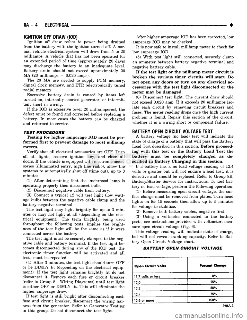
OPEN CIRCUIT VOLTAGE TEST
A battery voltage (no load) test will indicate the
state of charge of a battery that will pass the Battery
Load Test described in this section. Before proceed
ing with this test or the Battery Load Test the
battery must be completely charged as de scribed in Battery Charging in this section. If a battery has a no load voltage reading of 12.4
volts or greater but will not endure a load test, it is
defective and should be replaced. Refer to Group 8B,
Battery/Starter Service for instructions. To test bat
tery no load voltage, perform the following operation: (1) Before measuring open circuit voltage, the sur
face charge must be removed from plates. Turn head lights on for 15 seconds then allow up to 5 minutes
for voltage to stabilize. (2) Remove both battery cables, negative first.
(3) Using a voltmeter connected to the battery
posts,
see instructions provided with voltmeter, mea sure open circuit voltage (Fig. 6). This voltage reading will indicate state of charge,
but will not reveal cranking capacity. Refer to Bat
tery Open Circuit Voltage chart.
BATTERY OPEN CIRCUIT VOLTAGE
Open
Circuit
Volts
Percent
Chang©
11.7
volts
or
less
0%
12.0 25%
12.2 50%
12.4 75%
12.6
or more 100%
918A-3
Page 327 of 1502
8A
- 6
ELECTRICAL
•
Fig.
10
Load
50%
Cold
Crank
Rating Note Voltage
LOAD TEST TEMPERATURE
Minimum
Voltage
Temperature
Minimum
Voltage
P c°
9.6 70 and
above
21 and
above
9.5 60
16
9.4 50 10
9.3 40 4
9.1 30 -1
8.9 20 -7
8.7 10 -12
8.5 0
•
18
J908A-4
BATTERY
CHARGING
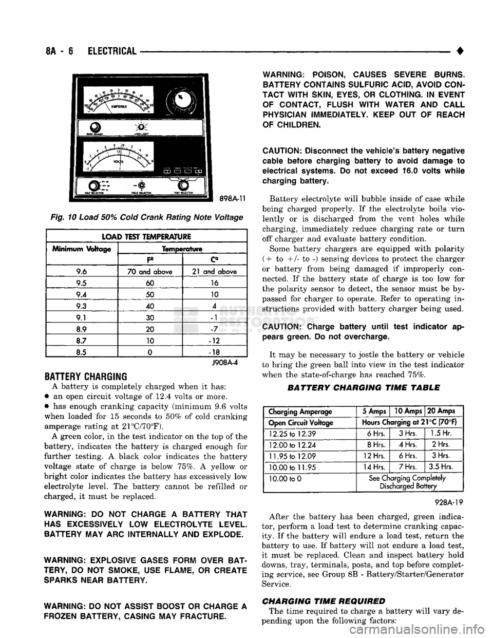
A battery is completely charged when it has:
• an open circuit voltage of 12.4 volts or more.
• has enough cranking capacity (minimum 9.6 volts
when loaded for 15 seconds to 50% of cold cranking amperage rating at 21°C/70°F). A green color, in the test indicator on the top of the
battery, indicates the battery is charged enough for
further testing. A black color indicates the battery
voltage state of charge is below 75%. A yellow or
bright color indicates the battery has excessively low electrolyte level. The battery cannot be refilled or
charged, it must be replaced.
WARNING:
DO NOT
CHARGE
A
BATTERY
THAT
HAS
EXCESSIVELY
LOW
ELECTROLYTE LEVEL.
BATTERY MAY ARC INTERNALLY AND EXPLODE.
WARNING: EXPLOSIVE GASES FORM OVER BAT
TERY,
DO NOT
SMOKE, USE FLAME,
OR
CREATE
SPARKS
NEAR BATTERY.
WARNING:
DO
NOT ASSIST BOOST
OR
CHARGE
A
FROZEN BATTERY, CASING MAY FRACTURE. WARNING: POISON, CAUSES SEVERE BURNS.
BATTERY CONTAINS SULFURIC ACID, AVOID CON
TACT WITH
SKIN,
EYES,
OR
CLOTHING.
IN
EVENT OF CONTACT, FLUSH
WITH
WATER
AND
CALL PHYSICIAN IMMEDIATELY. KEEP
OUT OF
REACH
OF CHILDREN.
CAUTION:
Disconnect
the
vehicle's
battery
negative
cable
before
charging
battery to
avoid
damage
to
electrical
systems.
Do not
exceed
16.0
volts
while
charging
battery.
Battery electrolyte will bubble inside of case while
being charged properly. If the electrolyte boils vio lently or is discharged from the vent holes while
charging, immediately reduce charging rate or turn
off charger and evaluate battery condition.
Some battery chargers are equipped with polarity
(+ to +/- to -) sensing devices to protect the charger
or battery from being damaged if improperly con
nected. If the battery state of charge is too low for
the polarity sensor to detect, the sensor must be by
passed for charger to operate. Refer to operating in structions provided with battery charger being used.
CAUTION:
Charge
battery
until
test
indicator
ap
pears
green.
Do not
overcharge.
It may be necessary to jostle the battery or vehicle
to bring the green ball into view in the test indicator
when the state-of-charge has reached 75%.
BATTERY CHARGING TIME TABLE
Charging
Amperage
5 Amps
10 Amps
20 Amps
Open
Circuit
Voltage
Hours
Charging
at21°C
(70°F)
12.25
to
12.39
6Hrs.
3Hrs.
1.5
Hr.
12.00
to
12.24
8Hrs.
4Hrs.
2Hrs
11.95
to
12.09
12Hrs.
6Hrs.
3Hrs.
10.00
to
11.95
14Hrs.
7Hrs.
3.5 Hrs.
10.00 to
0
See
Charging
Completely
Discharged
Battery
928A-19
After the battery has been charged, green indica
tor, perform a load test to determine cranking capac ity. If the battery will endure a load test, return the
battery to use. If battery will not endure a load test, it must be replaced. Clean and inspect battery hold
downs, tray, terminals, posts, and top before complet
ing service, see Group 8B - Battery/Starter/Generator Service.
CHARGING TIME REQUIRED The time required to charge a battery will vary de
pending upon the following factors:
Page 328 of 1502
•
ELECTRICAL
8A - 7
(1) Size
of
Battery—
A
completely discharged
large heavy-duty battery requires more than twice
the recharging time
as a
completely discharged small capacity battery.
WARNING: NEVER EXCEED
20
AMPS
WHEN
CHARGING
A
COLD
(-1°C/30°F)
BATTERY,
PER
SONAL
INJURY
MAY RESULT.
(2) Temperature—
A
longer time will
be
needed
to charge
a
battery
at -18°C (0°F)
than
at
27°C
(80°F).
When
a
fast charger
is
connected
to a
cold
battery, current accepted
by
battery will
be
very
low
at first. Then,
in
time,
the
battery will accept
a
higher rate
as
battery warms.
(3) Charger Capacity—
A
charger that supplies
only
5
amperes requires
a
much longer charging
time than
a
charger that supplies
20
amperes.
(4) State
Of
Charge—
A
completely discharged
battery requires more charging time than
a
partially charged battery. Electrolyte
is
nearly pure water
in a
completely discharged battery.
At
first
the
charging
current amperage will
be low. As
acid
is
forced from
the plates, inside
the
battery,
the
current amperate
will rise. Also,
the
specific gravity
of the
electrolyte will rise, bringing
the
green
dot
into view.
CHARGING
COMPLETELY
DISCHARGED
BATTERY
The following procedure should
be
used
to
recharge
a completely discharged battery. Unless procedure
is
properly followed,
a
good battery
may be
needlessly replaced.
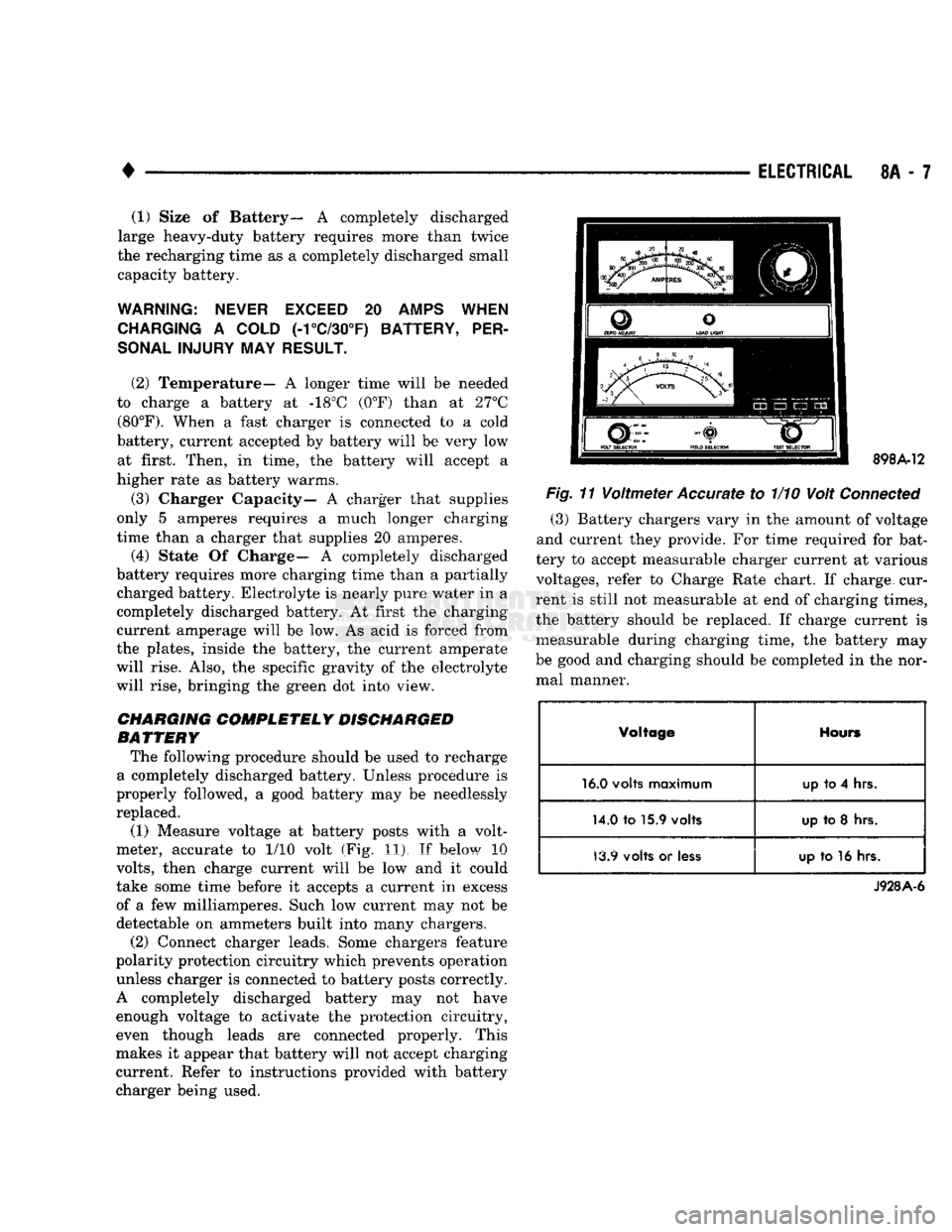
(1) Measure voltage
at
battery posts with
a
volt
meter, accurate
to 1/10
volt
(Fig, 11). If
below
10
volts,
then charge current will
be low and it
could
take some time before
it
accepts
a
current
in
excess of
a few
milliamperes. Such
low
current
may not be
detectable
on
ammeters built into many chargers.
(2) Connect charger leads. Some chargers feature
polarity protection circuitry which prevents operation
unless charger
is
connected
to
battery posts correctly.
A completely discharged battery
may not
have enough voltage
to
activate
the
protection circuitry,
even though leads
are
connected properly. This
makes
it
appear that battery will
not
accept charging
current. Refer
to
instructions provided with battery
charger being used.
VOLT
SELECTOR
FIELD
SELECTOR
TEST
SELECTOR
898A-12
Fig.
11
Voltmeter
Accurate
to 1/10
Volt
Connected
(3) Battery chargers vary
in the
amount
of
voltage
and current they provide.
For
time required
for
bat
tery
to
accept measurable charger current
at
various voltages, refer
to
Charge Rate chart.
If
charge, cur
rent
is
still
not
measurable
at end of
charging times,
the battery should
be
replaced.
If
charge current
is
measurable during charging time,
the
battery
may
be good
and
charging should
be
completed
in the
nor mal manner.
Voltage
Hours
16.0
volts
maximum
up
to
4
hrs.
14.0
to
15.9
volts
up
to 8 hrs
13.9
volts
or
less up
to 16
hrs.
J928A-6
Page 331 of 1502
8A
- 10
ELECTRICAL
•
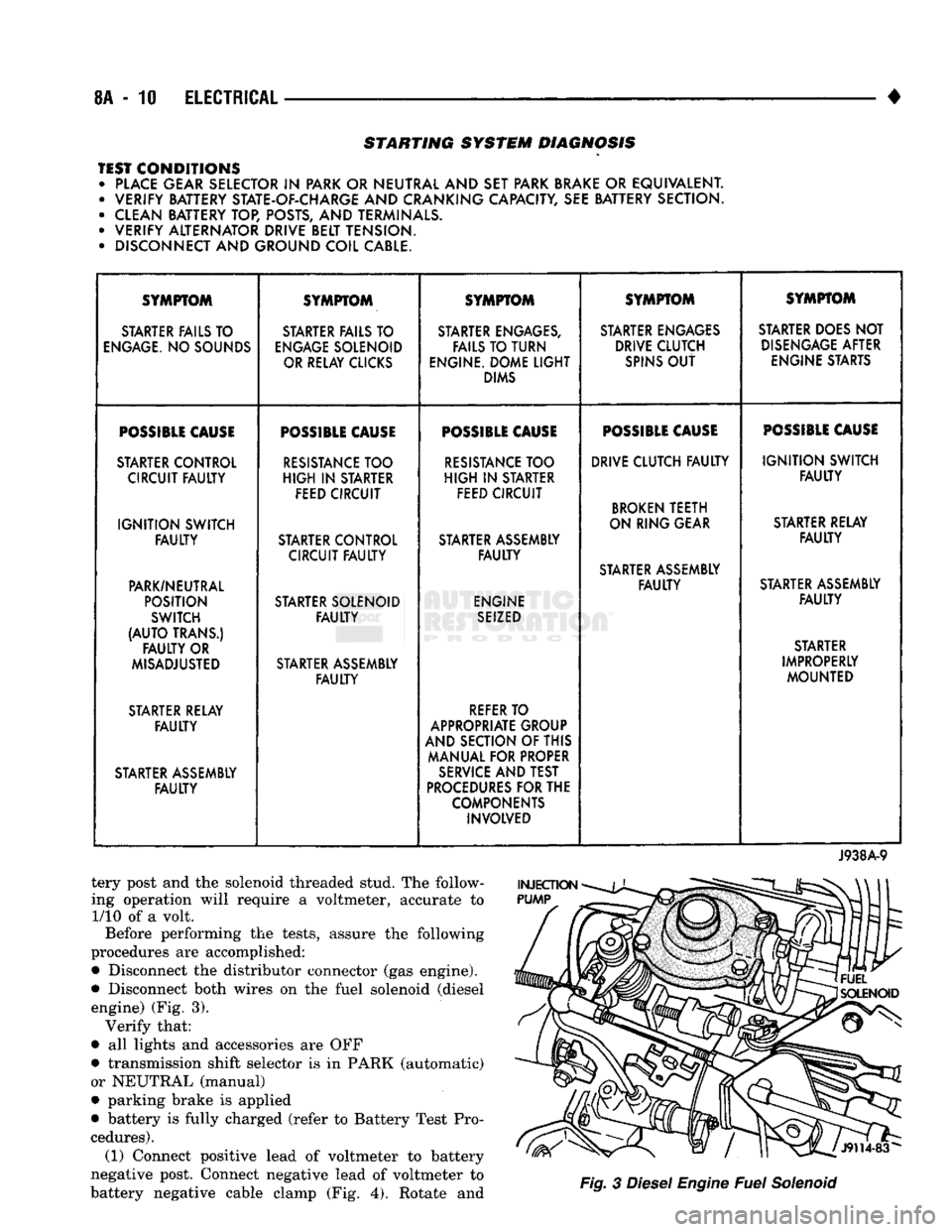
STARTING SYSTEM DIAGNOSIS
TEST CONDITIONS • PLACE GEAR SELECTOR
IN
PARK OR NEUTRAL AND SET PARK BRAKE
OR
EQUIVALENT. • VERIFY BATTERY STATE-OF-CHARGE AND CRANKING CAPACITY, SEE BATTERY SECTION.
• CLEAN BATTERY TOP, POSTS, AND TERMINALS.
• VERIFY ALTERNATOR DRIVE BELT TENSION.
• DISCONNECT AND GROUND COIL CABLE. SYMPTOM
SYMPTOM SYMPTOM SYMPTOM SYMPTOM
STARTER FAILS TO STARTER FAILS TO STARTER ENGAGES, STARTER ENGAGES STARTER DOES NOT
ENGAGE.
NO SOUNDS
ENGAGE
SOLENOID FAILS TO TURN DRIVE CLUTCH
DISENGAGE
AFTER
OR RELAY CLICKS ENGINE. DOME
LIGHT
SPINS
OUT
ENGINE STARTS
DIMS
POSSIBLE
CAUSE
POSSIBLE
CAUSE
POSSIBLE
CAUSE
POSSIBLE
CAUSE
POSSIBLE
CAUSE
STARTER CONTROL
RESISTANCE
TOO
RESISTANCE
TOO DRIVE CLUTCH
FAULTY
IGNITION
SWITCH
CIRCUIT
FAULTY
HIGH
IN
STARTER
HIGH
IN
STARTER
FAULTY
FEED CIRCUIT FEED CIRCUIT
BROKEN
TEETH
IGNITION
SWITCH ON RING GEAR
STARTER RELAY
FAULTY
STARTER CONTROL STARTER ASSEMBLY
FAULTY
CIRCUIT
FAULTY FAULTY
STARTER ASSEMBLY
PARK/NEUTRAL
FAULTY
STARTER ASSEMBLY
POSITION STARTER SOLENOID ENGINE
FAULTY
SWITCH
FAULTY
SEIZED
(AUTO
TRANS.) STARTER
FAULTY
OR STARTER
MISADJUSTED STARTER ASSEMBLY IMPROPERLY
FAULTY
MOUNTED
STARTER RELAY
REFER
TO
FAULTY
APPROPRIATE GROUP
AND SECTION OF THIS
MANUAL FOR PROPER
STARTER ASSEMBLY
SERVICE
AND TEST
FAULTY
PROCEDURES
FOR THE
COMPONENTS INVOLVED
J938A-9
tery post and the solenoid threaded stud. The follow
ing operation will require a voltmeter, accurate to 1/10 of a volt.
Before performing the tests, assure the following
procedures are accomplished:
•
Disconnect the distributor connector (gas engine).
•
Disconnect both wires on the fuel solenoid (diesel engine) (Fig. 3). Verify that:
•
all lights and accessories are OFF
•
transmission shift selector is in PARK (automatic)
or NEUTRAL (manual)
•
parking brake is applied
•
battery is fully charged (refer to Battery Test Pro
cedures). (1) Connect positive lead of voltmeter to battery
negative post. Connect negative lead of voltmeter to
battery negative cable clamp (Fig. 4). Rotate and
Fig.
3
Diesel
Engine
Fuel
Solenoid
Page 339 of 1502
8A
- 18
ELECTRICAL
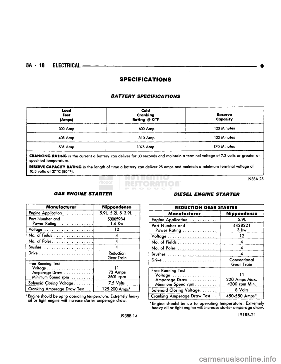
• BATTERY SPECIFICATIONS
Load
Test
(Amps)
Cold
Cranking
Rating @ 0°F Reserve
Capacity
300 Amp 600 Amp 120 Minutes
405 Amp 810 Amp 133 Minutes
535 Amp 1075 Amp 170 Minutes
CRANKING
RATING
is the
current
a
battery
can deliver for 30
seconds
and maintain a
terminal
voltage of 7.2 volts or greater at specified
temperature.
RESERVE
CAPACITY RATING
is the length of
time
a
battery
can deliver 25 amps and maintain a minimum
terminal
voltage of 10.5 volts
at27°C
(80 °F).
J938A-25 GAS ENGINE STARTER
DIESEL ENGINE STARTER
Manufacturer
Nippondenso
Engine
Application 5.9L, 5.21 e\ 3.9L
Part Number and
53005984
Power Rating 1.4 Kw
Voltage 12
No.
of Fields 4
No.
of
Poles.
4
Brushes
4
Drive Reduction
Gear Train
Free
Running Test Voltage 11
Amperage Draw ............ 73
Amps
Minimum Speed rpm 3601 rpm
Solenoid
Closing
Voltage 7.5 Volts
Cranking Amperage Draw Test . . .
125-200
Amps*
*
Engine
should
be up to operating
temperature.
Extremely heavy oil or tight engine
will
increase
starter
amperage draw.
J938B-14
REDUCTION
GEAR
STARTER
Manufacturer
Nippondenso
Engine
Application 5.9L
Part Number and Power Rating ..............
4428221
3
kw
Voltage 12
No.
of Fields 4
No.
of
Poles
4
Brushes
.................... 4
Drive Conventional
Gear Train
Free
Running Test Voltage .
Amperage Draw
Minimum Speed rpm 11
220
Amps
Max.
4200
rpm Min.
Solenoid
Closing
Voltage. 8 Volts
Cranking Amperage Draw Test . .
450-550
Amps*
*
Engine
should be up to operating heavy oil or tight engine
will
increase
temperature.
Extremely
starter
amperage draw. J918B-21
SPECIFICATIONS
Page 350 of 1502
•
BATTERY/STARTER/GENERATOR
SERVICE
8B - 9
Load
Test
(Amps)
cold
Cranking
Rating
@ 0°F
Reserve
Capacity
300 Amp 600 Amp 120 Minutes
405 Amp 810 Amp 133 Minutes
535 Amp 1075 Amp
170 Minutes
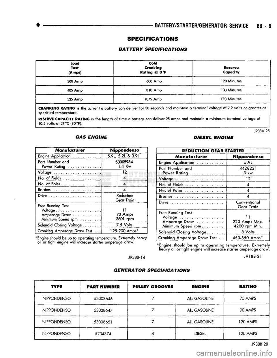
CRANKING
RATING
is the
current
a
battery
can
deliver
for 30
seconds
anej
maintain
a
terminal
voltage
of 7.2
volts
or
greater
at
specified
temperature.
RESERVE
CAPACITY RATING
is the
length
of
time
a
battery
can
deliver
25
amps and maintain
a
minimum
terminal
voltage
of
10.5 volts
at
27 °C (80
°F).
J938A-25
GAS ENGINE DIESEL ENGINE
Manufacturer
Nippondenso
Engine
Application 5.9L, 5.2L
&
3.9L
Part Number and
53005984
Power Rating
1.4
Kw
Voltage
12
No.
of
Fields 4
No.
of
Poles. 4
Brushes
4
Drive Reduction
Gear
Train
Free
Running Test Voltage 11
Amperage Draw 73 Amps
Minimum Speed
rpm
3601
rpm
Solenoid
Closing Voltage 7.5 Volts
Cranking Amperage Draw Test
. . .
125-200
Amps*
*
Engine
should be up to operating
temperature.
Extremely heavy oil
or
tight engine
will
increase
starter
amperage draw.
J938B-14
REDUCTION
GEAR
STARTER
Manufacturer
Nippondenso
Engine
Application 5.9L
Part Number
and
Power Rating
4428221
3
kw
Voltage
12
No.
of
Fields
4
No.
of
Poles 4
Brushes
4
Drive Conventional
Gear Train
Free
Running Test Voltage
Amperage Draw
Minimum Speed
rpm
11
220 Amps Max.
4200
rpm Min.
Solenoid
Closing Voltage 8 Volts
Cranking Amperage Draw Test
. .
450-550
Amps*
*
Engine
should
be up to
operating
temperature.
Extremely heavy oil or tight engine
will
increase
starter
amperage draw.
J918B-21
GENERATOR SPECIFICATIONS
TYPE
PHUT
HUMSIR
PULLEY
GROOVES
ENGINE
RATING
NIPPONDENSO
53008646
7
ALL GASOLINE 75 AMPS
NIPPONDENSO
53008647
7
ALL GASOLINE 90 AMPS
NIPPONDENSO
53008651
7
ALL GASOLINE
120
AMPS
NIPPONDENSO
5234374
8
DIESEL
120 AMPS
J938B-28
SPECIFICATIONS
BATTERY SPECIFICATIONS
Page 622 of 1502
•
3.9L ENGINE
9 - 17
3.9L
ENGINE SERVICE PROCEDURES
INDEX
page
Camshaft
31
Crankshaft
38
Crankshaft Main Bearings
39
Crankshaft Rear
Oil
Seals
. 40
Cylinder Block
41
Cylinder Head Cover
. , 21
Cylinder Heads
. 22
Distributor
33
Engine
Assembly .........................
20
Engine
Front Mounts
17
Engine
Rear Mount
18
Front Crankshaft
Oil
Seal Replacement ........
31
GENERAL INFORMATION
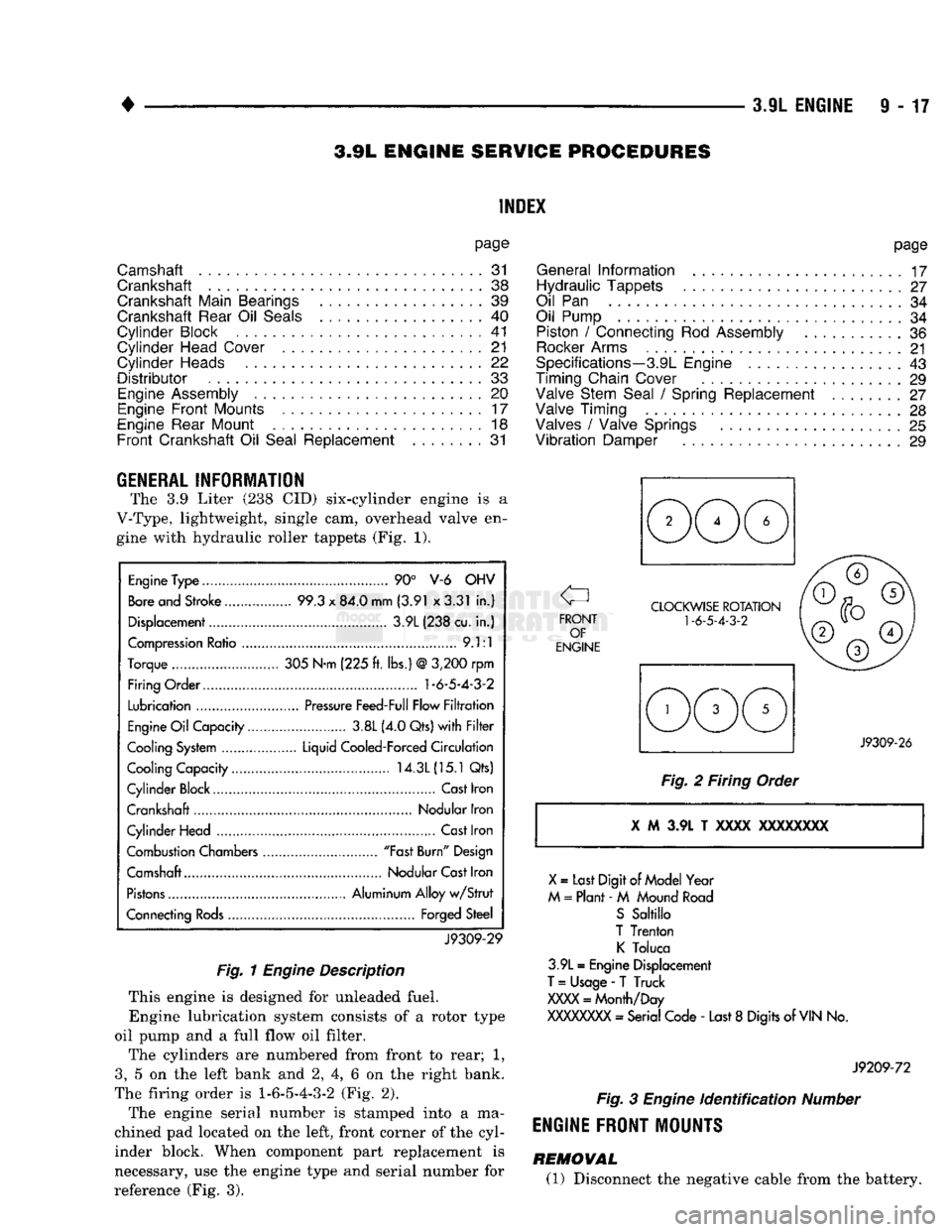
The 3.9 Liter (238 CID) six-cylinder engine is a
V-Type, lightweight, single cam, overhead valve en gine with hydraulic roller tappets (Fig. 1).
Engine
Type
90° V-6 OHV
Bore
and Stroke 99.3
x
84.0 mm (3.91 x3.31
in.)
Displacement 3.9L (238 cu.
in.)
Compression
Ratio
9.1:1
Torque 305 N-m (225
ft.
lbs.)
@
3,200
rpm
Firing Order.... 1-6-5-4-3-2
Lubrication
Pressure
Feed-Full Flow
Filtration
Engine
Oil
Capacity 3.8L (4.0 Qts)
with Filter
Cooling
System
Liquid Cooled-Forced
Circulation
Cooling Capacity 14.3L
(15.1
Qts)
Cylinder Block Cast Iron
Crankshaft Nodular Iron
Cylinder Head
Cast
Iron
Combustion Chambers "Fast
Burn"
Design
Camshaft Nodular
Cast
Iron
Pistons
Aluminum Alloy
w/Strut
Connecting
Rods
Forged Steel
J9309-29
Fig.
1
Engine
Description
This engine is designed for unleaded fuel. Engine lubrication system consists of a rotor type
oil pump and a full flow oil filter.
The cylinders are numbered from front to rear; 1,
3,
5 on the left bank and 2, 4, 6 on the right bank.
The firing order is
1-6-5-4-3-2
(Fig. 2).
The engine serial number is stamped into a ma
chined pad located on the left, front corner of the cyl
inder block. When component part replacement is
necessary, use the engine type and serial number for
reference (Fig. 3).
page
General
Information
17
Hydraulic Tappets
27
Oil
Pan 34
Oil Pump
34
Piston
/
Connecting
Rod
Assembly
36
Rocker
Arms
21
Specifications—3.9L Engine
43
Timing Chain Cover
29
Valve Stem Seal
/
Spring Replacement ........
27
Valve Timing
28
Valves
/
Valve Springs
25
Vibration
Damper
29
J9309-26
Fig.
2 Firing Order i M 3.9L T xxxx
XXXXXXXX
X
=
Last Digit
of
Model Year
M
=
Plant -
M
Mound
Road
S
Sabillo
T Trenton
K
Toluca
3.9L
=
Engine Displacement
T
=
Usage
-
T Truck
XXXX
=
Month/Day
XXXXXXXX
- Serial Code -
Last
8
Digits of
VIN
No.
J9209-72
Fig.
3
Engine
identification
Number
ENGINE FRONT MOUNTS
REMOVAL (1) Disconnect the negative cable from the battery.