clutch DODGE TRUCK 1993 Service Repair Manual
[x] Cancel search | Manufacturer: DODGE, Model Year: 1993, Model line: TRUCK, Model: DODGE TRUCK 1993Pages: 1502, PDF Size: 80.97 MB
Page 4 of 1502
GROUP TAB LOCATOR
Introduction
0
Lubrication
and
Maintenance
2
Front Suspension
and
Axle
3
Rear Suspension
and
Axles
5
Brakes
6
Clutch
7
Cooling System
8
Electrical
9
Engines
11
Exhaust System
and
Intake
Manifold
13
Frame
and Bumpers
14
Fuel
System
16
Propeller Shafts
19
Steering
21
Transmission
and
Transfer Case
22
Wheels and Tires
23
Body Components
24
Heating
and Air
Conditioning
25
Emission Control Systems Component and System Index
Service Manual Comment Forms (Rear
of
Manual)
Page 23 of 1502
0 - 4
LUBRICATION
AND
MAINTENANCE
COMPONENTS
REQUIRING
NO
LUBRICATION
There are many components that should not be lu
bricated. The components that should not be lubri cated are: • Air pumps
• Generator bearings
• Brake booster cylinder • Clutch release bearings
• Distributors
• Drive belts • Drive belt idler pulleys • Drive shaft center bearings
• Idler arms • Rubber bushings
• Starter motor bearings • Suspension strut bearings
• Rear spring shackle bolts • Rear wheel bearings (not equipped with a Dana
or 70 axle)
• Throttle control cables
• Throttle linkage ball joints • Water pump bearings
Page 41 of 1502
0
- 22
LUBRICATION
AND
MAINTENANCE
DRIVETRAIN
INDEX
page
Axles
25
Clutch
and
Brake Pedal
Bushings
............ 22
Clutch Master Cylinder
22
Drive Shafts
26
page
Front Axle U-Joint
and
Pivot Bearings
......... 26
Transfer
Case
(4WD
Vehicles)
. . ........ 24
Transmissions
. 22
CLUTCH
AND
BRAKE PEDAL
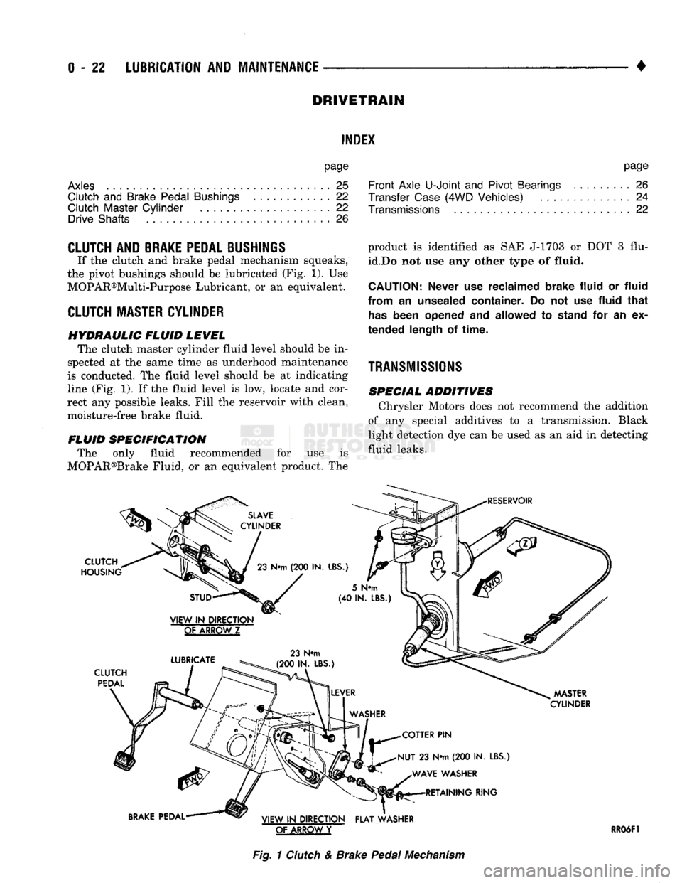
If the clutch and brake pedal mechanism squeaks,
the pivot bushings should be lubricated (Fig. 1). Use
MOPAR®Multi-Purpose Lubricant, or an equivalent.
CLUTCH
MASTER CYLINDER
HYDRAULIC FLUID LEVEL The clutch master cylinder fluid level should be in
spected at the same time as underhood maintenance
is conducted. The fluid level should be at indicating
line (Fig. 1). If the fluid level is low, locate and cor
rect any possible leaks. Fill the reservoir with clean,
moisture-free brake fluid.
FLUID SPECIFICATION The only fluid recommended for use is
MOPAR®Brake Fluid, or an equivalent product. The
SLAVE
CYLINDER
CLUTCH
HOUSING
23
N«m
(200 IN.
LBS.)
product is identified as SAE J-1703 or DOT 3 flu
id.Do not use any other type of
fluid.
CAUTION:
Never
use
reclaimed brake fluid
or
fluid
from
an
unsealed container.
Do not use
fluid that
has
been opened
and
allowed
to
stand
for an ex
tended length
of
time.
TRANSMISSIONS
SPECIAL ADDITIVES Chrysler Motors does not recommend the addition
of any special additives to a transmission. Black
light detection dye can be used as an aid in detecting
fluid leaks.
RESERVOIR
STUD
VIEW
IN
DIRECTION
GtAKBQWZ
LUBRICATE
CLUTCH
PEDAL
23 N#m
(200 IN. LBS.)
5
N«m
(40 IN.
LBS
MASTER
CYLINDER
COTTER
PIN
NUT
23 N*m (200 IN.
LBS.) WAVE WASHER RETAINING RING
BRAKE
PEDAL VIEW
IN
DIRECTION FLAT WASHER
OF ARROW
Y
RR06F1
Fig.
1
Clutch
& Brake
Pedal
Mechanism
Page 106 of 1502
• ___— . ^
FRONT
SUSPENSION
AND
AXLE
2 - 53
SCREWDRIVER
J9202-70
Fig.
9
Lock
Ring
Removal
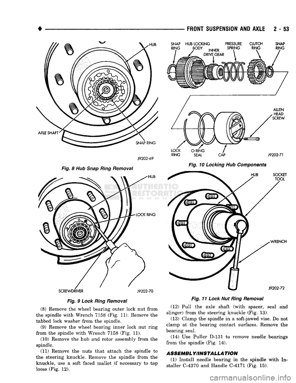
(8) Remove the wheel bearing outer lock nut from
the spindle with Wrench 7158 (Fig. 11). Remove the
tabbed lock washer from the spindle.
(9) Remove the wheel bearing inner lock nut ring
from the spindle with Wrench 7158 (Fig. 11).
(10) Remove the hub and rotor assembly from the
spindle.
(11) Remove the nuts that attach the spindle to
the steering knuckle. Remove the spindle from the knuckle, use a soft faced mallet if necessary to tap
loose (Fig. 12).
SNAP
HUB
LOCKING
PRESSURE
CLUTCH
SNAP
RING
SEAL
CAP
J9202-71
Fig.
10
Locking
Hub
Components
Fig.
11
Lock
Nut
Ring
Removal
(12) Pull the axle shaft (with spacer, seal and
slinger) from the steering knuckle (Fig. 13).
(13) Clamp the spindle in a soft-jawed vise. Do not
clamp at the bearing contact surfaces. Remove the
bearing seal.
(14) Use Puller D-131 to remove needle bearings
from the spindle (Fig. 14).
ASSEMBL
Y/INSTALLA
TION
(1) Install needle bearing in the spindle with In
staller C-4370 and Handle C-4171 (Fig. 15).
Page 130 of 1502
•
REAR
SUSPENSION
AND
AXLE
3 - 1
CONTENTS
page
8
3/8 and 9 1/4
AXLE
11
GENERAL
INFORMATION
1
MODEL
60 and 70
AXLES
29
POWER-LOK DIFFERENTIAL
55
REAR
SUSPENSION—2WD
and
4WD VEHICLES
3
page
SERVICE
DIAGNOSIS
6
SPECIFICATIONS
27
SURE-GRIP
DIFFERENTIAL SERVICE
28
TORQUE SPECIFICATIONS
59
TRAC-LOK DIFFERENTIAL
51
GENERAL INFORMATION
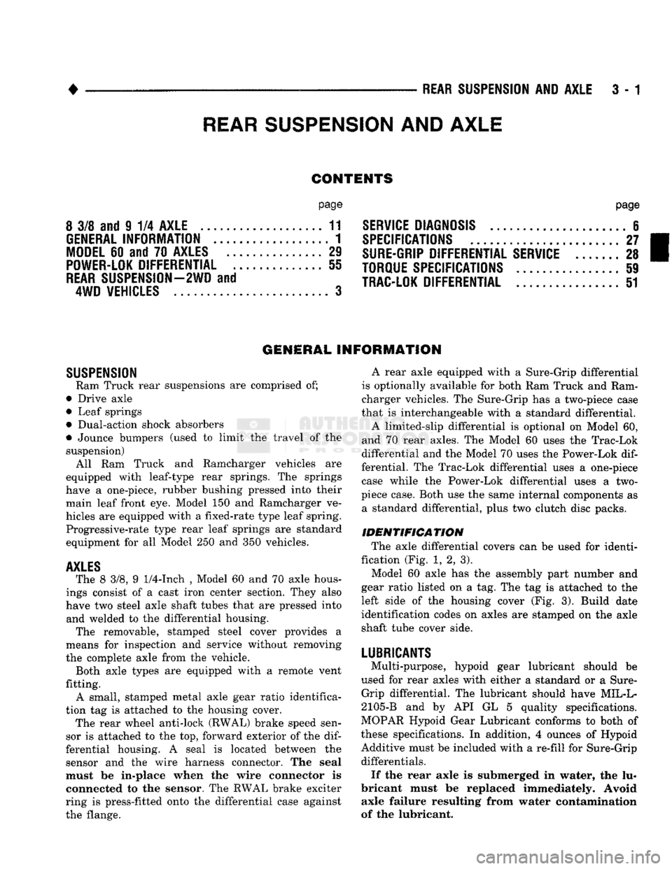
SUSPENSION
Ram Truck rear suspensions
are
comprised
of;
• Drive axle
• Leaf springs
• Dual-action shock absorbers
• Jounce bumpers (used
to
limit
the
travel
of the
suspension) All
Ram
Truck
and
Ramcharger vehicles
are
equipped with leaf-type rear springs.
The
springs
have
a
one-piece, rubber bushing pressed into their main leaf front
eye.
Model
150 and
Ramcharger
ve
hicles
are
equipped with
a
fixed-rate type leaf spring. Progressive-rate type rear leaf springs
are
standard equipment
for all
Model
250 and 350
vehicles.
AXLES
The
8 3/8, 9
1/4-Inch
,
Model
60 and 70
axle hous
ings consist
of a
cast iron center section. They also
have
two
steel axle shaft tubes that
are
pressed into and welded
to the
differential housing. The removable, stamped steel cover provides
a
means
for
inspection
and
service without removing
the complete axle from
the
vehicle. Both axle types
are
equipped with
a
remote vent
fitting. A small, stamped metal axle gear ratio identifica
tion
tag is
attached
to the
housing cover. The rear wheel anti-lock (RWAL) brake speed sen
sor
is
attached
to the top,
forward exterior
of the dif
ferential housing.
A
seal
is
located between
the
sensor
and the
wire harness connector.
The
seal
must
be
in-plaee when
the
wire connector
is
connected
to the
sensor.
The
RWAL brake exciter
ring
is
press-fitted onto
the
differential case against
the flange. A rear axle equipped with
a
Sure-Grip differential
is optionally available
for
both
Ram
Truck
and
Ram
charger vehicles.
The
Sure-Grip
has a
two-piece case
that
is
interchangeable with
a
standard differential.
A limited-slip differential
is
optional
on
Model
60,
and
70
rear axles.
The
Model
60
uses
the
Trac-Lok
differential
and the
Model
70
uses
the
Power-Lok
dif
ferential.
The
Trac-Lok differential uses
a
one-piece case while
the
Power-Lok differential uses
a two-
piece case. Both
use the
same internal components
as
a standard differential, plus
two
clutch disc packs.
IDENTIFICATION The axle differential covers
can be
used
for
identi
fication (Fig.
1, 2, 3).
Model
60
axle
has the
assembly part number
and
gear ratio listed
on a tag. The tag is
attached
to the
left side
of the
housing cover
(Fig. 3).
Build date
identification codes
on
axles
are
stamped
on the
axle
shaft tube cover side.
LUBRICANTS
Multi-purpose, hypoid gear lubricant should
be
used
for
rear axles with either
a
standard
or a
Sure- Grip differential.
The
lubricant should have MIL-L-
2105-B
and by API GL 5
quality specifications.
MOPAR Hypoid Gear Lubricant conforms
to
both
of
these specifications.
In
addition,
4
ounces
of
Hypoid Additive must
be
included with
a
re-fill
for
Sure-Grip differentials.
If
the
rear axle
is
submerged
in
water,
the lu
bricant must
be
replaced immediately. Avoid axle failure resulting from water contamination
of
the
lubricant.
REAR
SUSPENSION
AND
AXLE
Page 137 of 1502
3
- 8
REAR SUSPENSION
AND
AXLE
• level. Where axle bearing damage is slight, the noise
is usually not noticeable at speeds above 30 mph.
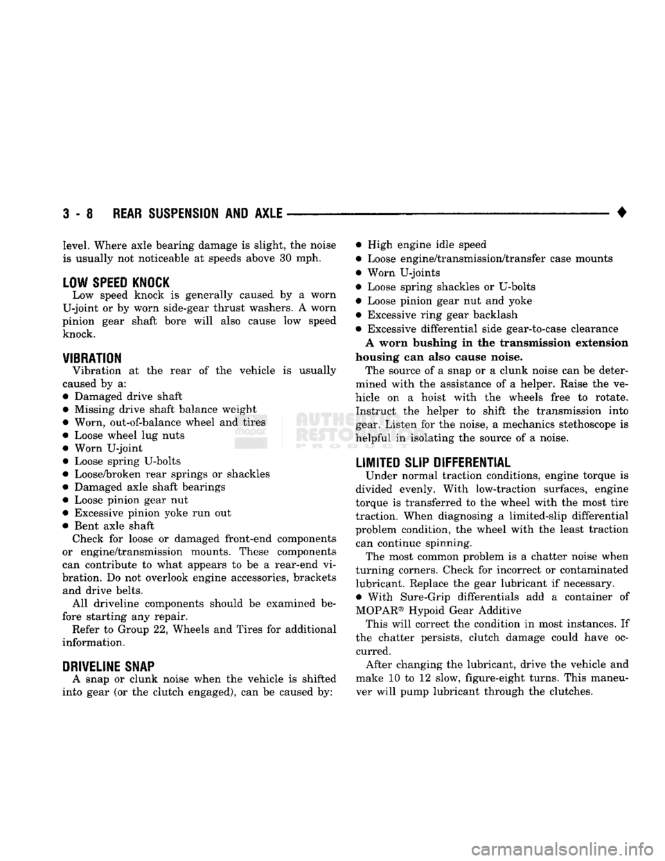
LOW SPEED KNOCK
Low speed knock is generally caused by a worn
U-joint or by worn side-gear thrust washers. A worn
pinion gear shaft bore will also cause low speed knock.
VIBRATION
Vibration at the rear of the vehicle is usually
caused by a:
• Damaged drive shaft
• Missing drive shaft balance weight
• Worn, out-of-balance wheel and tires
• Loose wheel lug nuts
• Worn U-joint • Loose spring U-bolts
• Loose/broken rear springs or shackles
• Damaged axle shaft bearings
• Loose pinion gear nut
• Excessive pinion yoke run out
• Bent axle shaft Check for loose or damaged front-end components
or engine/transmission mounts. These components
can contribute to what appears to be a rear-end vi
bration. Do not overlook engine accessories, brackets and drive belts. All driveline components should be examined be
fore starting any repair. Refer to Group 22, Wheels and Tires for additional
information.
DRIVELINE SNAP
A snap or clunk noise when the vehicle is shifted
into gear (or the clutch engaged), can be caused by: • High engine idle speed
• Loose engine/transmission/transfer case mounts
9
Worn U-joints
• Loose spring shackles or U-bolts
• Loose pinion gear nut and yoke
• Excessive ring gear backlash
• Excessive differential side gear-to-case clearance A worn bushing in the transmission extension
housing can also cause noise. The source of a snap or a clunk noise can be deter
mined with the assistance of a helper. Raise the ve
hicle on a hoist with the wheels free to rotate. Instruct the helper to shift the transmission into gear. Listen for the noise, a mechanics stethoscope is
helpful in isolating the source of a noise.
LIMITED
SLIP DIFFERENTIAL
Under normal traction conditions, engine torque is
divided evenly. With low-traction surfaces, engine
torque is transferred to the wheel with the most tire
traction. When diagnosing a limited-slip differential
problem condition, the wheel with the least traction can continue spinning. The most common problem is a chatter noise when
turning corners. Check for incorrect or contaminated lubricant. Replace the gear lubricant if necessary.
• With Sure-Grip differentials add a container of
MOPAR® Hypoid Gear Additive This will correct the condition in most instances. If
the chatter persists, clutch damage could have oc curred. After changing the lubricant, drive the vehicle and
make 10 to 12 slow, figure-eight turns. This maneu
ver will pump lubricant through the clutches.
Page 138 of 1502
REAR
SUSPENSION
AND
AXLE
3 - 9
SERVICE DIAGNOSIS
Condition
Possible
Cause
Correction
WHEEL
NOISE
AXLE
SHAFT
NOISE
AXLE
SHAFT
BROKE
DIFFERENTIAL
CASE
CRACKED
DIFFERENTIAL
GEARS
SCORED
LOSS
OF
LUBRICANT
(a) Wheel loose.
(b) Faulty, brinelled
wheel
bearing.
(a) Misaligned axle shaft tube.
(b) Bent or sprung axle shaft. (c) End play in drive pinion bearings.
(d) Excessive gear backlash
between
ring
gear
and pinion gear.
(e) Improper adjustment of drive pinion
gear
shaft bearings.
(f) Loose drive pinion gearshaft yoke nut.
(g) Improper
wheel
bearing adjustment. (h) Scuffed gear tooth contact surfaces.
(a) Misaligned axle shaft tube.
(b) Vehicle overloaded.
(c) Erratic clutch operation
(d) Grabbing clutch.
(a) Improper adjustment of
differential
bearings.
(b) Excessive ring gear backlash.
(c) Vehicle overloaded. (d) Erratic clutch operation.
(a) Insufficient lubrication.
(b) Improper grade of lubricant.
(c) Excessive spinning of one
wheel/tire.
(a) Lubricant
level
too high. (a) Tighten loose nuts.
(b) Faulty or brinelled bearings must be
replaced.
(a) Inspect axle shaft
tube
alignment. Correct as necessary.
(b) Replace bent or sprung axle shaft.
(c) Refer to Drive Pinion Bearing Pre-Load Adjustment.
(d) Check adjustment of ring gear
backlash
and pinion gear. Correct as
necessary.
(e) Adjust drive pinion shaft bearings.
(f) Tighten drive pinion gearshaft yoke nut
with
specified torque.
(g) Readjust as necessary.
(h) If necessary, replace scuffed gears.
(a) Replace broken axle shaft
after
correcting axle shaft
tube
alignment.
(b) Replace broken axle shaft. Avoid
excessive
weight on vehicle.
(c) Replace broken axle shaft
after
inspecting for other possible
causes.
Avoid
erratic
use of clutch.
(d) Replace broken axle shaft. Inspect clutch and make necessary repairs or adjustments.
(a) Replace cracked case; examine gears and bearings for possible damage. At
reassembly,
adjust
differential
bearings properly.
(b) Replace cracked case; examine gears and bearings for possible damage. At
reassembly,
adjust ring gear backlash properly.
(c) Replace cracked case; examine gears and bearings for possible damage.
Avoid
excessive weight on vehicle.
(d) Replace cracked case.
After
inspecting for other possible
causes,
examine
gears
and bearings for possible
damage.
Avoid
erratic
use of clutch.
(a) Replace scored gears. Scoring marks
on
the drive face of gear
teeth
or in
the bore are caused by instantaneous
fusing
of the mating surfaces. Scored
gears
should be replaced.
Fill
rear
differential
housing to
required
capacity
with
proper lubricant. Refer to
Specifications.
(b) Replace scored gears. Inspect all
gears
and bearings for possible
damage.
Clean and
refill
differential
housing
to
required
capacity
with
proper lubricant.
(c) Replace scored gears. Inspect all
gears,
pinion bores and shaft for
damage.
Service as necessary.
(a) Drain excess lubricant by removing
fill
plug and allow lubricant to
level
at lower edge of
fill
plug hole.
J9003-49
Page 139 of 1502
3-10
REAR SUSPENSION
AND
AXLE
SERVICE DIAGNOSIS (CONT'D)
Condition
Possible
Cause
Correction
AXLE OVERHEATING
GEAR TEETH BROKE
(RING GEAR
AND
PINION)
AXLE NOISE
(b) Worn axle
shaft
seals.
(c) Cracked
differential
housing.
(d) Worn
drive
pinion
gear
shaft
seal.
(e) Scored and worn yoke.
(f) Axle cover not
properly
sealed.
(a)
Lubricant
level
too low. (b)
Incorrect
grade of
lubricant.
(c) Bearings
adjusted
too
tight.
(d) Excessive gear wear.
(e)
Insufficient
ring
gear backlash,
(a) Overloading.
(b)
Erratic
clutch
operation.
(c) Ice-spotted pavements.
(d) Improper adjustments.
(a)
Insufficient
lubricant.
(b) Improper
ring
gear and
drive
pinion
gear
adjustment.
(c) Unmatched
ring
gear and
drive
pinion
gear.
(d) Worn
teeth
on
ring
gear or
drive
pinion
gear.
(e) Loose
drive
pinion
gear
shaft
bearings.
(f) Loose
differential
bearings.
(g) Misaligned or sprung
ring
gear.
(h) Loose
differential
bearing cap bolts. (b) Replace worn
seals.
(c) Repair or replace housing as
necessary.
(d) Replace worn
drive
pinion
gear
shaft
seal.
(e) Replace worn or scored yoke and seal.
(f) Remove cover and clean flange and reseal.
(a)
Refill
differential
housing. (b) Drain,
flush
and
refill
with
correct
amount of the
correct
lubricant.
(c) Readjust bearings.
(d) Inspect gears for excessive wear or scoring. Replace as necessary.
(e) Readjust
ring
gear backlash and inspect gears for possible scoring.
(a) Replace gears. Examine
other
gears and bearings for possible damage. Replace parts as needed. Avoid
overloading of vehicle.
(b) Replace gears and examine the remaining parts for possible damage.
Avoid
erratic
clutch
operation.
(c) Replace gears. Examine the remaining parts for possible damage. Replace
parts as required.
(d) Replace gears. Examine
other
parts for possible damage. Ensure
ring
gear
backlash is
correct.
(a)
Refill
axle
with
correct
amount of the proper
lubricant.
Also inspect for leaks
and
correct
as necessary.
(b) Check
ring
gear and
pinion
gear
teeth
contact
pattern.
(c) Remove unmatched
ring
gear and
drive
pinion
gear. Replace
with
matched gear and
drive
pinion
gear
set.
(d) Check
teeth
on
ring
gear and
drive
pi nion gear for
correct
contact.
If necessary, replace
with
new
matched set.
(e) Adjust
drive
pinion
gearshaft bearing preload
torque.
(f) Adjust
differential
bearing preload
torque.
(g) Measure
ring
gear
runout.
(h) Tighten
with
specified
torque.
J9003-50
Page 155 of 1502
3
- 28
REAR
SUSPENSION
AND
AXLE
•
SURE-GRIP
DIFFERENTIAL
SERVICE
GENERAL
INFORMATION
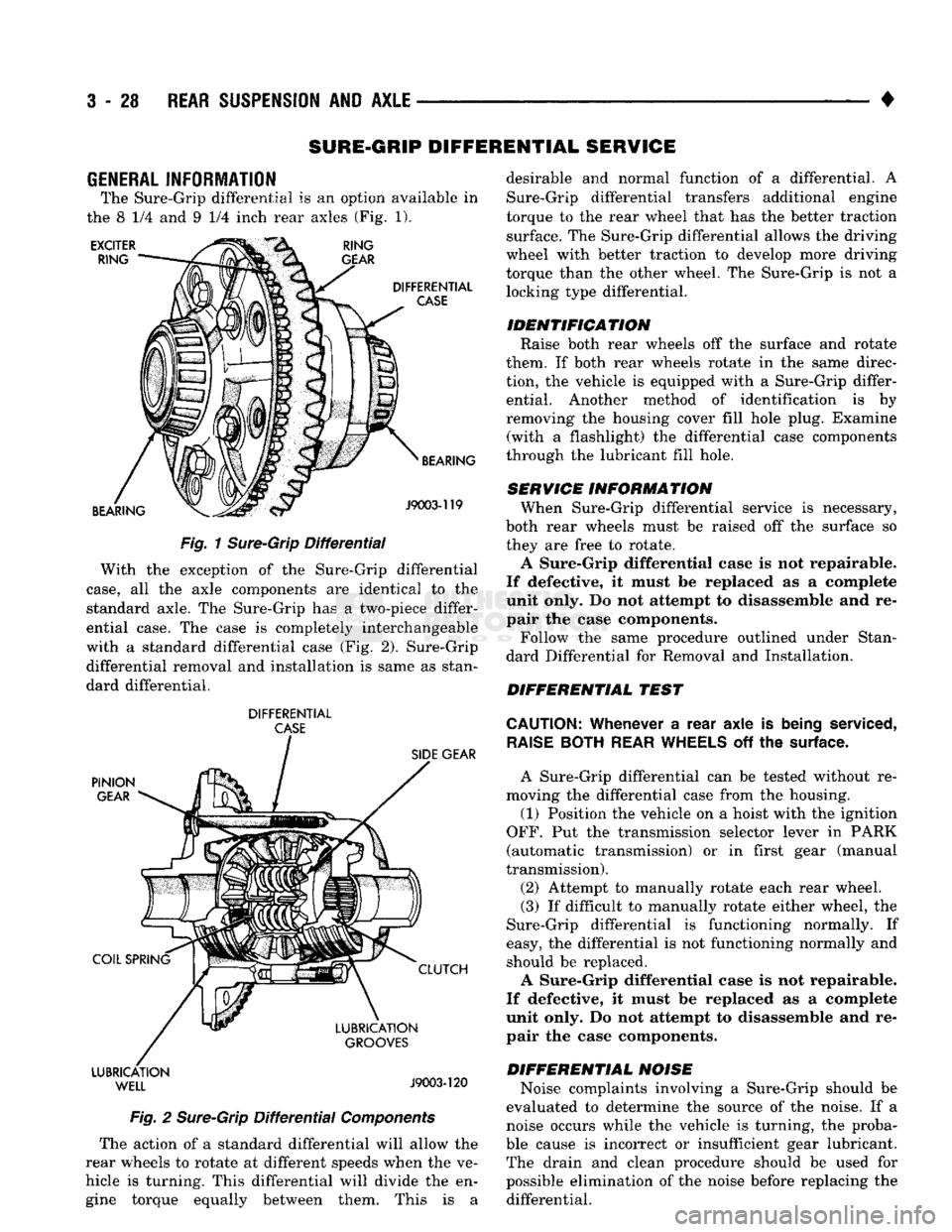
The Sure-Grip differential
is an
option available
in
the
8 1/4 and 9 1/4
inch rear axles
(Fig. 1).
EXCITER
RING RING
GEAR
DIFFERENTIAL
CASE
BEARING BEARING
J9003-119
Fig.
1
Sure-Grip
Differential
With
the
exception
of the
Sure-Grip differential
case,
all the
axle components
are
identical
to the
standard axle.
The
Sure-Grip
has a
two-piece differ
ential case.
The
case
is
completely interchangeable
with
a
standard differential case
(Fig. 2).
Sure-Grip differential removal
and
installation
is
same
as
stan
dard differential.
DIFFERENTIAL
CASE
PINION
GEAR
COIL SPRING LUBRICATION
WELL
SIDE
GEAR
CLUTCH
LUBRICATION
GROOVES
J9003-120
Fig.
2
Sure-Grip
Differential
Components
The action
of a
standard differential will allow
the
rear wheels
to
rotate
at
different speeds when
the ve
hicle
is
turning. This differential will divide
the en
gine torque equally between them. This
is a
desirable
and
normal function
of a
differential.
A
Sure-Grip differential transfers additional engine
torque
to the
rear wheel that
has the
better traction surface.
The
Sure-Grip differential allows
the
driving
wheel with better traction
to
develop more driving
torque than
the
other wheel.
The
Sure-Grip
is not a
locking type differential.
IDENTIFICATION Raise both rear wheels
off the
surface
and
rotate
them.
If
both rear wheels rotate
in the
same direc
tion,
the
vehicle
is
equipped with
a
Sure-Grip differ ential. Another method
of
identification
is by
removing
the
housing cover fill hole plug. Examine (with
a
flashlight)
the
differential case components
through
the
lubricant fill hole.
SERVICE INFORMATION When Sure-Grip differential service
is
necessary,
both rear wheels must
be
raised
off the
surface
so
they
are
free
to
rotate.
A Sure-Grip differential case
is not
repairable.
If defective,
it
must
be
replaced
as a
complete
unit only.
Do not
attempt
to
disassemble
and re
pair
the
case components.
Follow
the
same procedure outlined under Stan
dard Differential
for
Removal
and
Installation.
DIFFERENTIAL TEST
CAUTION:
Whenever
a
rear axle
is
being
serviced,
RAISE
BOTH
REAR
WHEELS
off the
surface.
A Sure-Grip differential
can be
tested without
re
moving
the
differential case from
the
housing.
(1) Position
the
vehicle
on a
hoist with
the
ignition
OFF.
Put the
transmission selector lever
in
PARK
(automatic transmission)
or in
first gear (manual
transmission).
(2) Attempt
to
manually rotate each rear wheel.
(3)
If
difficult
to
manually rotate either wheel,
the
Sure-Grip differential
is
functioning normally.
If
easy,
the
differential
is not
functioning normally
and
should
be
replaced.
A Sure-Grip differential case
is not
repairable.
If defective,
it
must
be
replaced
as a
complete
unit only.
Do not
attempt
to
disassemble
and re
pair
the
case components.
DIFFERENTIAL NOISE Noise complaints involving
a
Sure-Grip should
be
evaluated
to
determine
the
source
of the
noise.
If a
noise occurs while
the
vehicle
is
turning,
the
proba
ble cause
is
incorrect
or
insufficient gear lubricant. The drain
and
clean procedure should
be
used
for
possible elimination
of the
noise before replacing
the
differential.
Page 156 of 1502
•
REAR
SUSPENSION
AND
AXLE
3-29
WARNING: WHEN SERVICING VEHICLES
WITH
SURE-GRIP,
DO NOT
USE THE ENGINE
TO
ROTATE
THE AXLE
AND
WHEELS. BOTH REAR WHEELS MUST BE RAISED AND
THE
VEHICLE SUPPORTED.
A
SURE-GRIP AXLE
CAN
EXERT ENOUGH FORCE
(IF ONE
WHEEL
IS IN
CONTACT
WITH
THE
SUR FACE)
TO
CAUSE
THE
VEHICLE
TO
MOVE.
LUBRICATION
Multi-Purpose Gear Lubricant, as defined by MIL-
L-2105-B (API GL-5) should be used in all axles.
MOPAR Hypoid Lubricant is recommended or equiv alent. In Sure-Grip differentials 4 ounces of MOPAR Hy
poid Gear Lubricant Additive must be added with each re-fill.
It is recommended the vehicle be driven through 10
to 12 slow, figure-eight turns. This ensures the lubri cant is thoroughly pumped through the Sure-Grip
differential clutches.
MODEL 60 and 70 AXLES
INDEX
page
Axle Shaft Removal/Installation
32
Complete Axle Removal/Installation
........... 33
Differential
Assembly
38
Differential
Disassembly
34
Drain
and Refill 31
General
Information
29
Lubricant
31
GENERAL
INFORMATION
The housing (Fig. 1) consists of an iron center cast
ing with axle shaft tubes extending from either side.
The tubes are pressed in to form a one-piece axle housing. The integral type housing, hypoid gear design has
the centerline of the pinion set below the centerline of the ring gear. The axles are equipped with full-floating axle
shafts,
meaning that loads are supported by the axle
housing tubes. The full-float axle shafts are retained
by bolts attached to the hub. The hub rides on two
bearings at the outboard end of the axle tube. The axle shafts can be removed without disturbing or re
moving the wheel bearings. The wheel bearings are
opposed tapered roller bearings that are part of the
hub/drum assembly.
page
Pinion Gear Depth Measurement
and
Adjustment
with Tool Set C-758-D6 43
Pinion Gear Depth Measurement
and
Adjustment
with
Tool
Set
D-116
. 40
Pinion Shaft Seal
31
Specifications
50
Wheel Bearing Service
33
The removable, stamped steel cover provides a
means for inspection and service without removing
the complete axle from the vehicle.
A small, stamped metal axle gear ratio identifica
tion tag is attached to the housing cover via one of
the cover bolts. This tag also identifies the number of
ring and pinion teeth.
The differential case is a one-piece design. The
dif
ferential pinion mate shaft is retained with a roll
pin. Model 70 axles with the optional Powr-Lok use a
two piece differential case. Differential bearing pre load and ring gear backlash are adjusted by the use
of shims located between the differential bearing
cones and case.